
Related Manuals for JAI CV-M91


Summary of Contents for JAI CV-M91
- Page 1 3 CCD RGB Color Camera CV-M91 Operation Manual Camera: Revision A Manual: Version 1.1 M91Manualjan19.doc JPT 19-01-04...
-
Page 2: Table Of Contents
7.2. Jumper settings inside ...19 7.3. Switch and jumper positions ...20 7.3. RS-232C control ...21 7.4. CV-M91command list ...21 7.5. Camera Control Tool for CV-M91 ...22 8. External Appearance and Dimensions ... 23 9. Specifications ... 23 9.1. Spectral sensitivity ...23 9.2. -
Page 3: General
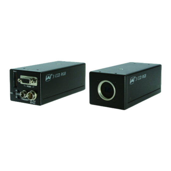
1. General The CV-M91 3 CCD RGB color camera is a new updated version of CV-M90. The prism is improved, and new CCD sensors are used. The new CCD sensor has 5 dB higher sensitivity, 15 dB lower smear and 4 dB higher dynamic range. Now there are Y/C output and input for composite sync. -
Page 4: Locations And Functions
4. Locations and Functions Prism Lens mount (C-mount). Thread max 4 mm Switch SW1 for mode settings 6 pin Trigger input and RS-232C connector 12 pin DC in/Sync connector 9 pin Sub-D connector for video Red gain potentiometer Blue gain potentiometer Switch for one push white balance 10. -
Page 5: Pin Assignment
5. Pin Assignment 5.1. 12-pin Multi-connector (DC-IN/Trigger) Type: HR10A-10R-12PB-01(Hirose) male. Plugs for cable: HR10A-10P-12S (Seen from rear of camera.) Fig. 2. 12-pin connector. 5.2. 6-pin Multi-connector (TRIGGER and RS232C) Type: HR10A-7R-6PB (Hirose) male Plugs for cable: HR10A-7P-6S Seen from rear. Fig. -
Page 6: 9-Pin Sub D-Connector (Video)
5.3. 9-pin Sub D-connector (Video) Type: male. (Seen from rear of camera.) Fig. 4. 9-pin connector. 5.4. Input and Output Circuits In the following schematic diagrams the input and output circuits for video and timing signals are shown. Video outputs The video output is a 75 Ω... -
Page 7: Prism Unit
HD, VD, WEN, EEN and PCLK output The output circuit for HD, VD, WEN, EEN and PCLK are complementary emitter followers with 75 Ω in series. Output level is 4V. (Non-terminated). 5.5. Prism unit For best color performance, the lens should be designed for 1/3”... -
Page 8: Functions And Operations
6. Functions and Operations The different camera modes and functions can be set by switches and jumpers. Some functions like RGB setup and white clip can only be changed via RS-232C. Function names within “ “ are names used in camera control tool. 6.1. -
Page 9: Internal Sync Out/Wen Out
6.1.2. Internal sync out/WEN out On pin #7 on 9 pin sub-D connector, the factory setting is the internal composite sync signal out. By jumper settings it can be changed to WEN out. Refer to “7. Configuring the Camera.” To use this mode: Set function on PK8407: JP303 o, JP304 s for sync output. -
Page 10: Trigger Modes
6.2. Trigger Modes This camera can operate in 5 primary modes. 1 non-triggered, 3 external H synchronous trigger modes and 1 long time integration mode. Normal continuous Mode Edge Pre-select Mode. Pulse Width Control Mode. Start Stop Mode Long time integration In normal continuous mode and edge pre-select mode the shutter time can be selected from the 8 fixed steps. -
Page 11: Continuous Operation (Non Triggered)
6.2.1. Continuous Operation (Non triggered) Trigger Mode Normal. It is for applications where the camera is continuous running without external trigger. The shutter will work in all 8 steps up to 1/10,000 second. Refer to “7. Configuring the Camera.” To use this mode: Set function: Trigger mode “Normal”. - Page 12 CV-M91 Fig. 15. Vertical timing PAL interlaced Fig. 16. Vertical timing PAL non-interlaced. Field accumulation - 11 -...
- Page 13 CV-M91 Fig. 17. Vertical timing NTSC interlaced Fig. 18. Vertical timing NTSC non- interlaced. Field accumulation - 12 -...
-
Page 14: Edge Pre-Select Mode
6.2.2. Edge Pre-select Mode The exposure will start at the first HD after the trigger leading edge, and it stops after the selected shutter time, and the resulting video is read out. An EEN pulse indicate the accumulation time, and a WEN pulse that the resulting video read out. Refer to “7. -
Page 15: Pulse Width Control Mode
6.2.3. Pulse Width Control Mode The exposure will start at the first HD after the trigger leading edge, and it stops between the first and second HD after the trigger trailing edge. An EEN pulse indicate the accumulation time, and a WEN pulse indicates that the resulting video is read out. Refer to “7. -
Page 16: Start Stop Mode
6.2.4. Start Stop Mode The exposure time is controlled by the interval between the ext. trigger and the ext. VD signal. The exposure starts at the first HD pulse after the falling edge of the ext. trigger, and stops 14.5 H after the falling edge of the VD pulse. -
Page 17: Long Time Integration
6.2.5. Long time integration The exposure time is the interval between 2 ext. VD pulses sent to the VD input. (Pin No. 7 of the 12-pin connector). The exposure starts after input of the first ext. VD pulse, and ends after the next input of the next ext. -
Page 18: Other Functions
6.3. Other Functions. Refer to “7. Configuring the Camera.” Scanning: SW1-5 on rear selects interlaced or non-interlaced. Non-interlaced PAL = 312H in EVEN field. Non-interlaced NTSC = 262 H in ODD field. Gamma: SW1-6 on rear for gamma select. Gamma = 1 or gamma =0.45. Gain: SW1-7 on rear select manual gain or AGC. -
Page 19: Configuring The Camera
7. Configuring the Camera 7.1 Switch settings The switch positions are shown in factory setting. Names in bold italic is factory setting. 7.1.1. SW1 on rear panel SW 1 on rear < < SHUTTER < Normal < > Random TRIGGER INTERLACE Intel. -
Page 20: Jumper Settings Inside
7.2. Jumper settings inside Factory settings is shown in bold italic HD/VD input output on pin #6 and #7 on 12 pin connector. Jumper HD/VD in HD/VD out Remarks JP305 short open JP306 open short JP308 short open JP309 open short HD/VD input on pin #6 and #7 or composite VS signal in on pin #7. -
Page 21: Switch And Jumper Positions
7.3. Switch and jumper positions Front SW 604 SW 604 for Video output Fig. 37. Switches on PK8404. VR 7 Fig. 35. Board positions. JP310 JP311 JP315 JP318 JP319 JP302 JP309 JP305 JP 301 JP 313 JP 312 JP 304 JP 303 JP 308 Fig. -
Page 22: Rs-232C Control
7.3. RS-232C control The CV-M91 camera functions can be set up via the RS-232C port on the 6 pin HR connector. The JAI camera control tool for CV-M91 can be used for it. To use this mode: Set function: Control. SW1-8 on rear to ON. RS-232C. (Switch setting before power on). -
Page 23: Camera Control Tool For Cv-M91
CV-M91 7.5. Camera Control Tool for CV-M91 From www.jai.com Camera Control Tool for Windows 98/NT/2000 can be downloaded. The control tool contains a camera control program and tools for making your own program. For the integrator and experienced user, the Camera Control Tool is much more than a program with a window interface. -
Page 24: External Appearance And Dimensions
Use only lenses designed for 1/3” 3 CCD cameras. 9. Specifications 9.1. Spectral sensitivity The resulting relative response for the prism and the CCD sensor characteristics combined. Fig. 41. Outline. Wave length (nm) Wave length (nm) Fig. 42. Spectral sensitivity for CV-M91 - 23 -... -
Page 25: Specification Table
9.2. Specification table Specifications Scanning system Frame rate Line frequency Pixel frequency CCD sensors Sensing area Effective pixels Pixels in video output Cell size Resolution horizontal Sensitivity (on sensor) S/N ratio Video outputs. (DC coupled) Video output level Gamma Gain Gain range Accumulation Synchronization... -
Page 26: Cv-M91 Opto-Mechanical Specifications
CV-M91 9.3. CV-M91 Opto-mechanical specifications Fig. 43. Opto mechanical specifications. - 25 -... -
Page 27: Appendix
CV-M91 10. Appendix 10.1. Precautions Personnel not trained in dealing with similar electronic devices should not service this camera. The camera contains components sensitive to electrostatic discharge. The handling of these devices should follow the requirements of electrostatic sensitive components. -
Page 28: Users Record
Company and product names mentioned in this manual are trademarks or registered trademarks of their respective owners. JAI A-S cannot be held responsible for any technical or typographical errors and reserves the right to make changes to products and documentation without prior notification.
Need help?
Do you have a question about the CV-M91 and is the answer not in the manual?
Questions and answers