Table of Contents
Advertisement
Quick Links
Download this manual
See also:
User Manual
Advertisement
Table of Contents

Related Manuals for JAI CM-200GE


Summary of Contents for JAI CM-200GE
- Page 1 - 0 - Preliminary Version Subject to changes User's Manual CM-200GE CB-200GE Digital Monochrome / Color Progressive Scan GigE Vision Camera Document Version: First Draft Camera Revision: 0...
-
Page 2: Table Of Contents
7. GigE Vision Streaming Protocol (GVSP) ..............- 15 - 7.1. Digital Video Output (Bit Allocation)..............- 15 - 7.2. Bit Allocation (Pixel Format / Pixel Type) – CM-200GE ........... - 15 - 7.2.1. GVSP_PIX_MONO8 (8bit) ................ - 15 - 7.2.2. - Page 3 CM-200 GE / CB-200 GE 8.4.5. Vertical binning ................... - 29 - 8.5. Operation Modes ..................- 30 - 8.5.1 Continuous operation ................- 30 - 8.5.2 Edge Pre-select Trigger Mode ..............- 31 - 8.5.3 Pulse Width Control Trigger Mode ............. - 32 - 8.5.4 Sequential Trigger Mode ( EPS)..............
-
Page 4: General
Bayer images. Host-based color interpolation is required to display or save color images. The CM-200GE/CB-200GE also complies with the GenICam standards, as it has in internal XML file that is used to describe the functions/features of the camera. For further information on GenICam please go to www.emva.org. -
Page 5: Camera Nomenclature
• frames/second with external trigger and full resolution • Increased frame rate with vertical binning (CM-200GE only) and partial scan • Exposure time from 32μs to 2 sec. using Pulse Width Control trigger mode •... -
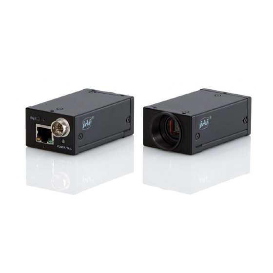
Page 6: Locations And Functions
CM-200 GE / CB-200 GE 4. Locations and Functions ③ ④ GigE ⑧ POWER / TRIG ① ② ⑦ ⑤ ⑥ 1 Lens mount C-mount (Note *1) 2 CCD sensor 1/1.8 inch CCD sensor 3 12-pin connector DC +12V power and GPIO interface 4 RJ-45 Gigabit Ethernet connector 5 LED... -
Page 7: Pin Assignment
CM-200 GE / CB-200 GE 5. Pin Assignment 5.1. 12-pin Multi-connector (DC-in/GPIO/Iris Video) Type: HR10A-10R-12PB (Hirose) male. Pin no. Signal Remarks (Seen from rear of camera.) +12 V DC input Opt IN 2 (-) / GND (*1) Opt IN 2 (+)/Iris Video out (*1) Opt IN 1 ( - ) Opt IN 1 ( + ) GPIO IN / OUT... -
Page 8: Gpio (Inputs And Outputs )
CM-200 GE / CB-200 GE 6. GPIO (Inputs and outputs ) 6.1. Overview All input and output signals pass through the GPIO (General Purpose Input and Output) module. The GPIO module consists of a Look-Up Table (LUT – Cross-Point Switch), 4 Pulse Generators and a 12-bit counter. -
Page 9: 12-Bit Counter
15.869KHz. 6.2. Optical Interface The new series of JAI GigE Vision camera implements optical interface for GPIO input and output by using photo coupler device. The photo coupler device has light emitting diode and photo transistor inside in general . The electronic signal is converted to the light in the light emitting diode and the light conducts photo transistor . -
Page 10: Recommended External Output Circuit Diagram For Customer
CM-200 GE / CB-200 GE 6.2.2 Recommended External Output circuit diagram for customer EXTERNAL OUTPUT User Camera side Inside hirose-12 connector Pin 8 and 10 User Power +12V +5V to +24V From Camera Circuit hirose-12 connector Pin 7 and 9 Fig.6. -
Page 11: Inputs And Outputs Table
CM-200 GE / CB-200 GE 6.3. Inputs and outputs table Output Port Time Pulse Pulse Pulse Pulse Trigger 0 Trigger 1 Stamp Generato Generato Generato Generato OUT1 OUT2 Reset × × × × × ○ ○ ○ ○ LVAL IN ×... -
Page 12: 12Bit Counter
Length Length These settings can be done with JAI Control tool which is included in the JAI SDK. The created pulse has the raising edge on the starting point and the falling edge on the ending point as described on the above. - Page 13 CM-200 GE / CB-200 GE Address Internal Name GenIcam name Access Size Value (range) 0xB008 Length Counter 0 0x00001 to 0xFFFFF 0xB00C Start point Counter 0(1) 0x00000 to 0xFFFFF 0x00: infinite 0x01: 1 time 0xB010 Start point Counter 0(2) 0xFF: 255 times 0xB014 End point Counter 0 0x00001 to 0xFFFFF...
-
Page 14: Gpio Programming Examples
CM-200 GE / CB-200 GE 6.5. GPIO programming examples 6.5.1 GPIO Plus PWC shutter Example: 10µs unit pulse width exposure control (PWC). Pixel clock is 65MHz. 650 clocks (750-100) equals 10µs. Address Register Value 0xA040 Trigger Mode 2 = PWC ( Pulse Width Control) 0xB000 Clock Choice 1 = Pixel Clock ( 65 MHz ) -
Page 15: Internal Trigger Generator
CM-200 GE / CB-200 GE 6.5.2 Internal Trigger Generator Create a trigger signal and trigger the camera Address Register Value 0xA040 Trigger Mode 1 = EPS 0xB000 Clock Choice 1 = Pixel Clock 0xB004 Counter Dividing Value 2079 = 1/2080 dev(Line Rate) 0xB008 Length Counter 0... -
Page 16: Gige Vision Streaming Protocol (Gvsp)
7. GigE Vision Streaming Protocol (GVSP) 7.1. Digital Video Output (Bit Allocation) Although the CM-200GE and CB-200GE are digital cameras, the image is generated by an analog component, the CCD sensor. The table and diagram below show the relationship between the analog CCD output level and the digital output. -
Page 17: Gvsp_Pix_Mono10_Packed ( 10 Bit )
CM-200 GE / CB-200 GE 7.2.3. GVSP_PIX_MONO10_PACKED ( 10 bit ) 2 3 4 5 6 7 8 9 0 1 X X 0 1 X X 2 3 4 5 6 7 8 9 2 3 4 5 6 7 8 9 0 1 X X 0 1 X X 2 3 4 5 6 7 8 9 Address Internal Name Access... -
Page 18: Gvsp_Pix_Baygb10 " Bayergb10
CM-200 GE / CB-200 GE 7.3.2 GVSP_PIX_BAYGB10 “ BayerGB10” Odd Line 1 Byte 2 Byte 3 Byte 4 Byte 0 1 2 3 4 5 6 7 8 9 X X X X X X 0 1 2 3 4 5 6 7 8 9 X X X X X X Even Line 0 1 2 3 4 5 6 7 8 9 X X X X X X 0 1 2 3 4 5 6 7 8 9 X X X X X X... -
Page 19: Functions And Operations
(NICs) and Switches/Routers are suitable for use with the GigE Vision compliant camera. JAI will endeavor to continuously verify these combinations, in order to give users the widest choice of GigE components for their system design. 8.2.1 Verified Network Interface Cards (NICs) -
Page 20: Video Data Rate (Network Bandwidth)
♦ In case using Jumbo Frame, the packet data will be improved 2 %. ♦ For CM-200GE and CB-200GE, the jumbo frame can be set at maximum 4040 Bytes ( Factory setting is 1440 Byte ). To set Jumbo Frame, refer chapter 8.2.3. - Page 21 CM-200 GE / CB-200 GE (6)Expand [Network adapters]. (7) Select target NIC, right-click, and click [Properties]. Note: The following procedure is the case you use Intel(R)1000. Accordingly the procedure is different if you use different NIC appeared on Network Adaptors. In that case, set the item of a similar content described here..
-
Page 22: Packet Delay
CM-200 GE / CB-200 GE (9) Select Jumbo Frames of Property, and select 9014 of Value. (10)Click [OK]. (11)Close [Device Manager]. (12)Close [System Properties] clicking [OK]. 8.2.4 Packet delay Packet Delay is one of GigE Vision functionalities. This function controls the data bandwidth through network. -
Page 23: Filter Driver Installation
JAI SDK in order to maximize the performance the camera. Click to Install GigE Vision Filter Driver . When the installation is completed and the camera is connected, the JAI Camera Control tool shows the Filter Driver as the network Interface. -
Page 24: Basic Functions
CM-200 GE / CB-200 GE 8.3. Basic functions The CM-200GE and CB-200GE cameras are progressive scan cameras with 10 or 8 bit video output in Gigabit Ethernet. The camera has 1/2, 1/4 or 1/8 partial scanning for faster frame rates. Vertical binning is also available. -
Page 25: Electronic Shutter
CM-200 GE / CB-200 GE 8.3.3 Electronic Shutter CM-200GE / CB-200GE has conventional shutter functions as well as the GenICam standard “Exposure Time Abs” function. Preset Shutter 10 steps preset shutter are available: OFF (1/31); 1/60, 1/100; 1/250; 1/500; 1/1,000; 1/2,000;... -
Page 26: Auto Iris Lens Video Output (12-Pin Hirose Connector)
Fig. 14. Iris video output. 8.3.5 Auto-detect LVAL-sync / a-sync. accumulation This function replaces the manual setting found in older JAI cameras. Whether accumulation is synchronous or a-synchronous in relationship to LVAL depends on the timing of the trigger input. -
Page 27: Rear Panel Indicator
Important Note: In GigE Vision, only Active Pixel Area is output through the GigE interface. However, CM-200GE and CB-200GE equip with “ OB transfer mode, 16 pixels for horizontal and 12 lines for vertical for OB in full scan mode are transferred, if this mode is used. -
Page 28: Horizontal Timing
CM-200 GE / CB-200 GE 8.4.2. Horizontal timing The LVAL period is shown for normal continuous mode. Horizontal Video Timing Full Frame Read out / Partial Read Out 1 LVAL 2080 clk = 32 μs 1 clk = 15.38 ns LVAL Valid data DATA OUT... -
Page 29: Partial Scanning
CM-200 GE / CB-200 GE 8.4.4. Partial Scanning The FVAL period is shown for 1/2 partial scan in normal continuous mode. 1 line = 26.7 μs Vertical Timing The below diagram and table provide vertical timing information for the fixed partial scan settings 1/2, 1/4, 1/3 and 2/3 Partial Frame Readout LVAL... -
Page 30: Vertical Binning
By activating this function, the frame rate is increased to 44.492 fps. This function is available only for CM-200GE. Important Note Vertical Binning can not be used together with the Partial Scanning. -
Page 31: Operation Modes
For timing details, refer to fig. 18. through fig. 23. To use this mode: Set function: Trigger mode Continuous Scanning Full, Partial scanning Vertical binning On/Off (CM-200GE only) Shutter mode Preset, Programmable, Auto Shutter speed Programmable exposure - 30 -... -
Page 32: Edge Pre-Select Trigger Mode
CM-200 GE / CB-200 GE 8.5.2 Edge Pre-select Trigger Mode An external trigger pulse initiates the capture, and the exposure time (accumulation time) is the fixed shutter speed set by registers. The accumulation can be LVAL synchronous or LVAL a-synchronous. The resulting video signal will start to be read out after the selected shutter time. -
Page 33: Pulse Width Control Trigger Mode
CM-200 GE / CB-200 GE LVAL_a-sync timing 5.37 μs ± 1μs Trig 1L(min .) CCD exposure Exposure time XEEN FVAL Trigger input during FVAL LOW period 2L to 3L LVAL a-SYNC mode setting Fig.25. Edge Pre-select LVAL a-sync Timing 8.5.3 Pulse Width Control Trigger Mode In this mode the accumulation time is equal the trigger pulse width. - Page 34 CM-200 GE / CB-200 GE LVAL_sync timing Trig 1L(Min.) LVAL 1L to 2L 1L(Max) CCD Exposure Exposure XEEN FVAL Trigger input whthin FVAL HIGH Period LVAL SYNC Mode Setting Fig. 26. Pulse width control. LVAL sync. LVAL_a-sync timing 5.37 μs ± 1 μs Trig 1L(Min.) CCD exposure...
-
Page 35: Sequential Trigger Mode ( Eps)
CM-200 GE / CB-200 GE 8.5.4 Sequential Trigger Mode ( EPS) The ROI, Shutter and Gain values can be preset up to 10 sequences. Along with every trigger input, the image data with the preset sequence is output as described below. Trigger Sequence Sequence 1... -
Page 36: Delayed Readout Mode ( Eps )
CM-200 GE / CB-200 GE ♦ The conditions for this table is that shutter speed should be set the same for all sequences. If the shutter speed is different , the difference of exposure time should be added. ♦ It is recommended to set the exposure time in the order from the shortest to the longer one. ♦... -
Page 37: Ob Transfer Mode
CM-200 GE / CB-200 GE 8.5.6 OB transfer Mode On this mode, the OB part is also transmitted. OB part can be used for black reference in the frame grabber board. This can be set by register 0xA41C for ON or OFF. OB Transfer Mode OFF OB Transfer Mode ON Normal Scan... -
Page 38: Operation Mode And Functions Matrix
JAI SDK provides the Camera Control Toll for JAI GigE Vision Camera. The followings are several hints to use this Control Tool. ♦ After start JAI Control Tool and connect the camera , the following control menu will be activate. - 37 -... - Page 39 CM-200 GE / CB-200 GE ♦ After click Feature Properties, and extend each item, the following control menu will be activate. ♦ For setting, each item should be active and change the value or select the necessary item. The following example is the Shutter setting. ♦...
- Page 40 Network conditions, set at the most appropriate value. The range of the packet size for CM-200GE and CB-200GE is from 1428 to 4040 and the factory default setting is 1428. Please note that the setting packet size is not memorized and therefore, it is necessary to set on every power up.
-
Page 41: Register Map
Current IP address 0x0034 Current subnet mask Current default 0x0044 gateway 0x0048 Manufacturer's name e.g. JAI 0x0068 Model name e.g. CM-200GE 0x0088 Device version Provides extended Manufacturer 0x00A8 manufacturer information specific info about the device. Camera serial number 0x00D8 Serial number... - Page 42 CM-200 GE / CB-200 GE persistent subnet 0x065C Valid if Persistent IP is enabled mask 0x066C persistent gateway Valid if Persistent IP is enabled Value / Range of Default Address Function Description value value number of number of available message 0x0900 This camera has 1 messaging channels...
- Page 43 CM-200 GE / CB-200 GE Decided by primary stream channel packet system size register 1440 0x0d04 SCPS0 packet size includes IP, XML file UDP&GVSP Header 32us Max primary stream channel packet 0x0d08 SCPD0 With 62.5MHz Tick delay register Time Not specified primary stream channel 0x0d18 SCDA0...
- Page 44 2=1/2 V Binning 0xA0C4 Manual Gain Level -84 to 336 0 to 1023 0xA0E0 User Black level 64 LSB=1023 32LSB=512 to 528 CM-200GE 0=OFF Test Stream 1=White Noise 0xA13C (Jumbo Packet 4=H Ramp Scale Check) 5=V Ramp Scale 6=Moving Ramp...
- Page 45 CM-200 GE / CB-200 GE 1= White Noise 4=H Ramp Scale 5=V Ramp Scale 6=Moving Ramp Scale 8=Color Bar 9=Color Bar 10=Moving Color 1=User area1 Allows use to save all camera Save Settings into 0xA300 2=User area2 settings. Last used area number User area 3=User area3 becomes new default.
- Page 46 CM-200 GE / CB-200 GE 0xC07C Sequence Gain 2 -84 to 326 Pre-program 2 Gain value 0xC080 Sequence Gain 3 -84 to 326 Pre-program 3 Gain value 0xC084 Sequence Gain 4 -84 to 326 Pre-program 4 Gain value 0xC088 Sequence Gain 5 -84 to 326 Pre-program 5 Gain value...
- Page 47 CM-200 GE / CB-200 GE Sequence ROI Width 0xC120 Size- X10 8 to 1392 Sequence ROI Height 0xC124 8 to 1040 Size-Y1 8 to 1040 Height Sequence ROI 0xC128 Size-Y2 8 to 1040 Height Sequence ROI 0xC12C Size-Y3 8 to 1040 Height Sequence ROI 0xC130...
- Page 48 CM-200 GE / CB-200 GE Sequence ROI 0xC170 0 to 1384 Offset-X10 Sequence ROI 0xC174 0 to 1032 Offset-Y1 Sequence ROI 0xC178 0 to 1032 Offset-Y2 Sequence ROI 0xC17C 0 to 1032 Offset-Y3 Sequence ROI 0xC180 0 to 1032 Offset-Y4 Sequence ROI 0xC184 0 to 1032...
- Page 49 CM-200 GE / CB-200 GE 0xA504 ROI1 Size X Width W.Max 0xA508 ROI1 Size Y Height H.Max 0xA50C ROI1 Offset X 0 to 1384 Horizontal offset 0xA510 ROI1 Offset Y 0 to 1032 Vertical offset 0=LOW 0xA600 Soft Trigger 0 1=HIGH 0xA604 Video Sending Flag...
- Page 50 CM-200 GE / CB-200 GE GPIO Registers: Counter Clock 0x00 25MHz 0xB000 source 0x01 Pixel Clock 0x000 Bypass 0x001 Divide by 2 Counter Divide by 0xB004 0x002 Divide by 3 Value 0xFFF Divide by 4096 0x00001 to Defines the length of the 0xB008 Length Counter 0 0xFFFFF...
- Page 51 CM-200 GE / CB-200 GE Free Run High Level Clear 0xB040 Counter 2 Clear Low Level Clear Rising Edge Clear Falling Edge Clear 0x00001 to 0xB044 Length Counter 3 Counter length 0xFFFFF Start point Counter 0x00001 to 0xB048 Start Point 3(1) 0xFFFFF 0x00: infinite...
-
Page 52: External Appearance And Dimensions
CM-200 GE / CB-200 GE 11. External Appearance and Dimensions 3-M3depth4 (0.2) (depth0.16) (2.64) (1.73) (2.95) GigE POWER / TRIG C-Mount (0.51) (2.32) 6-M3depth4 (0.2) (depth0.16) Outside size tolerance ± 0.3mm Fig. 28. Outline. - 51 -... -
Page 53: Specifications
CM-200 GE / CB-200 GE 12. Specifications 12.1. Spectral response Fig. 29. Spectral response for CM-200GE IR Filter Fig.30. Spectral response for CB-200GE - 52 -... -
Page 54: Specification Table
1624 (h) x 627 (v) 44.49 fps. H = 27.9 kHz ( *Note) Region-of-interest (ROI) User Definable. Memory read-out *Note: Vertical binning is for CM-200GE only Sensitivity on sensor (minimum) 0.21 Lux (Max. gain, Shutter OFF, 50% 0.7 Lux (Max. gain, Shutter OFF,50%... - Page 55 CM-200 GE / CB-200 GE Regulatory CE (EN61000-6-2 and EN61000-6-3), FCC part 15 class B, RoHS, WEEE 12V DC ± 10%. 3.5w Power C-mount Lens mount Rear protrusion on C-mount lens must be less than 10.0mm Dimensions 29 x 44 x 75 mm (HxWxD) Weight In order to get specified performance, it is needed to have approx.
-
Page 56: Appendix
When exporting this product, please follow the export regulation of your own country. References 1. This manual can for CM-140 MCL / CB-140 MCL can be downloaded from www.jai.com 2. Datasheet for CM-140 MCL / CB-140 MCL can be downloaded from www.jai.com... - Page 57 CM-200 GE / CB-200 GE 3. Camera control software can be downloaded from www.jai.com 4. Specifications for the CCD sensor Sony ICX-267AL and ICX-267AQ can be found on www.jai.com - 56 -...
- Page 58 CM-200 GE / CB-200 GE Index Auto Iris Lens, - 24 - Bayer mosaic color, - 3 - Bayer mosaic filter, - 3 - Bit Allocation, - 16 -, - 17 - Blemishes, - 53 - CAMERA TRIGGER, - 9 -, - 11 - Cat6 Ethernet, - 20 -, - 21 - CCD sensor, - 5 -, - 52 -, - 54 - CCD Sensor, - 26 -...
- Page 59 CM-200 GE / CB-200 GE transmission bandwidth, - 20 - Trigger input, - 5 -, - 24 - Trigger mode, - 33 -, - 34 -, - 36 - TTL IN, - 15 - Vertical Binning, - 21 -, - 22 -, - 23 -, - 29 - XML, - 3 - - 58 -...
-
Page 60: User's Record
Company and product names mentioned in this manual are trademarks or registered trademarks of their respective owners. JAI A-S cannot be held responsible for any technical or typographical errors and reserves the right to make changes to products and documentation without prior notification.
Need help?
Do you have a question about the CM-200GE and is the answer not in the manual?
Questions and answers