Table of Contents
Advertisement
Quick Links
Advertisement
Table of Contents

Related Manuals for JAI CV-M532


Summary of Contents for JAI CV-M532
- Page 1 Remote Head Monochrome CCD Camera CV-M532 Operation Manual (Rev.E)
-
Page 2: Declaration Of Conformity
CV-M532 DECLARATION OF CONFORMITY AS DEFINED BY THE COUNCIL DIRECTIVE 89/336/EEC EMC (ELECTROMAGNETIC COMPATIBILITY) WE HEREWITH DECLARE THAT THIS PRODUCT COMPLIES WITH THE FOLLOWING PROVISIONS APPLYING TO IT. EN-50081-1 EN-50082-1... -
Page 3: Table Of Contents
9.1. CCU ... 20 9.2. HEAD ... 20 10. Specifications ... 21 10.1. Spectral Sensitivity ... 21 11. Appendix ... 22 11.1. Precautions ... 22 11.2. Typical CCD Characteristics ... 22 12. User’s Record ... 23 CV-M532 - 2 -... -
Page 4: General
Precisely installed CCD imager (1/3") and miniature size (ø12mm) allows access to very contained spaces. The remote micro-head weights only 5g (0.031lbs) . The new 1/3" Hyper HAD imager employed in the CV-M532 provides superior sensitivity and higher dynamic range with improved smear level. -
Page 5: Main Features
CV-M532 3. Main Features • Miniature-sized remote head - ø12mm (0.47") • 1/3" Hyper HAD interline transfer CCD imager, 768(H) x 494(V) for EIA and 752(H) x 582(V) for CCIR • High resolution - horizontal 570 TV lines for EIA •... -
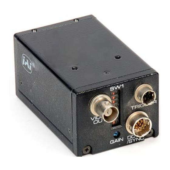
Page 6: Locations And Functions
8 CCD sensor 9 Focus adjustment ring 10 Camera head 11 connector CV-M532 : To connect camera head with camera control unit : To output video VS1.0Vp-p : To set shutter speed and function modes : Output WEN/EEN signal and input external trigger pulse, etc. -
Page 7: Pin Assignment
See “7.3. Jumper Settings” for more information. *2) In Edge Pre-select and Pulse Width Control mode do not input ext. VD signal. 5.2. 6-pin Multi-connector (TRIGGER) Type: HR10A-7R-6PB (Hirose) male Seen from rear. CV-M532 EEN output Ext. Trig input WEN output * Notes: The functions available on the 6-pin multi-connector are not effective in long time exposure mode. -
Page 8: Functions And Operations
CV-M532 6. Functions and Operations 6.1. Input/Output of HD/VD Signal 6.1.1. Input of External HD/VD Signal As factory setting the camera can be synchronized by external HD/VD signals. The signal level must be 4.0V p-p +/- 2.0V at the input with the 75 Ohm termination ON. To change to non-terminated input, see instructions in “7. - Page 9 1H more EXT HD INT HD INT VD 1.5H Exposure time 12.5H 0.5H 10.5H CCD out Video out CV-M532 Effective pixels No.10 to 251 242H Blanking Effective video - 8 - EIA : 1H = 63.5µs TRIG in 1.5H Exposure time 0.5H...
-
Page 10: Pulse Width Control Mode
75 Ohm termination is done with SW2-1 (HD) and SW2-2 (ext.trigger) on PK8057 board. Refer to Timing Chart and Cautions on next page. Detailed switch and jumper setting is described in “7. Mode Setting”. For connections see “5. Pin Assignment”. CV-M532 - 9 -... - Page 11 1H more EXT HD INT HD INT VD 1.5H Exposure time 12.5H 0.5H CCD out Video out CV-M532 Effective pixels No.10 to 251 242H Blanking Effective video - 10 - EIA : 1H = 63.5µs TRIG in 1.5H Exposure time 0.5H...
-
Page 12: Start/Stop Trigger Mode
HD/VD 75 Ohm termination is done with SW2-1 and SW2-2 on PK8057 board. Refer to Timing Chart and Cautions on next page. Detailed switch and jumper setting is described in “7. Mode Setting”. For connections see “5. Pin Assignment”. CV-M532 - 11 -... - Page 13 - Non-interlaced: 1 external trigger pulse per field a) Interlaced mode (Frame accumulation mode) b) 2:1 Interlaced mode (Field accumulation mode) Ext.Trg. Ext. VD Exposure time Video c) Non-interlace moded (Field accumulation mode) Ext.Trg. Ext. VD Exposure time Video CV-M532 - 12 -...
-
Page 14: Long Time Exposure Mode
Refer to Timing Chart and Cautions on next page. Detailed switch and jumper setting is described in “7. Mode Setting”. For connections see 5. “Pin Assignment”. CV-M532 VD pulse from the external HD/VD supply to the 1 V or more 2 V or integral number of 2V 1 V = 262.5 H... - Page 15 4. Timing of ext. VD signal in each accumulation mode has to be set, as described before. a) 2:1 Interlaced mode (Field accumulation mode) b) 2:1 Interlaced mode (Frame accumulation mode) c) Non interlaced mode (Field accumulation mode) CV-M532 - 14 -...
-
Page 16: Table For Shutter Time
7.1.2. Table for SW 1 Setting 7.1.3. Table for Shutter Time Caution on Shutter. The image can flicker when the illumination is AC powered. Highlighted parts of the image will show increasing smear at a shorter shutter time. CV-M532 - 15 -... -
Page 17: Ext. Trigger Shutter Mode
CV-M532 7.1.4. Ext. Trigger Shutter Mode When trigger select SW1-4 is ON. The camera is in ext. trigger shutter mode. The SW1-1, SW1-2 and SW1- 3 are for selecting the shutter speed. The range is from OFF to 1/10,000 second in 8 steps. For each external trigger pulse, the camera will make an exposure with the selected shutter speed. -
Page 18: Jumper Settings
“7.4.1. Board PK8057 Side A”. Pixel clock pulse will be output from pin no.9 of 12-pin multi-connector. Caution for Pixel Clock Output. When the pixel clock is enabled, it may cause interference with external equipment if it not properly shielded. CV-M532 - 17 -... -
Page 19: Location Of Sw2 And Jumpers
CV-M532 7.4. Location of SW2 and Jumpers Jumpers are shorted with a 0 Ohm resistor or by a soldering between the 2 points. To remove the solder tin from a jumper position, use a special tin remover such as de-soldering wick. -
Page 20: Adjustment Of Video Signal Output Level
CV-M532 8. Adjustment of Video Signal Output Level When an alignment of a video output signal is required, remove the camera housing and adjust potentiometers VR3, VR4 and VR5 on the PK8056 board while measuring their levels at the video output connector. -
Page 21: External Appearance
CV-M532 9. External Appearance Unit : mm (inches) 9.1 CCU 9.2 HEAD - 20 -... -
Page 22: Specifications
Factory setting: HD/VD input. Inputs TTL or 75 Ohm terminated by internal jumpers. Factory setting: 75 Ohm terminated. Note: Above specifications are subject to change without notice. 10.1. Spectral Sensitivity CV-M532 Monochrome "1/3" Hyper HAD IT CCD >56 dB (AGC off, Gamma 1) Composite VS signal 1.0 Vpp, 75 Ohm Manual –... -
Page 23: Appendix
Patterned Noise Patterned Noise When the CCD camera captures a dark object at high temperature or is used for long time integration, fixed pattern noise (shown as white dots) may appear on the video monitor screen. CV-M532 - 22 -... -
Page 24: User's Record
Phone +81 45 933 5400 www.jai.com Fax +81 45 931 6142 www.jai-corp.co.jp CV-M532 (Revision E) JAI America, Inc., USA Suite 450 23046 Avenida de la Carlota Laguna Hills, CA 92653 Phone +1 949 472 5900 Fax +1 949 472 5908...
Need help?
Do you have a question about the CV-M532 and is the answer not in the manual?
Questions and answers