
Related Manuals for JAI CMCB-140 MCL


Summary of Contents for JAI CMCB-140 MCL
- Page 1 User's Manual CM/CB-140 MCL CM/CB-140 PMCL CM-140MCL-UV CM-140PMCL-UV Digital Monochrome / Color Compact Mini-CL Camera Document Version: 3.3 CMB-140MCL/PMCL/UV_Ver.3.3_May2011...
- Page 2 JAI Ltd., Japan and may only be used by the purchasers of the product. JAI Ltd., Japan makes no warranty for the use of its product and assumes no responsibility for any errors which may appear or for damages resulting from the use of the information contained herein.
- Page 3 CM-140MCL / CM-140PMCL Supplement The following statement is related to the regulation on “ Measures for the Administration of the control of Pollution by Electronic Information Products “ , known as “ China RoHS “. The table shows contained Hazardous Substances in this camera. mark shows that the environment-friendly use period of contained Hazardous Substances is 15 years.
- Page 4 CB-140MCL / CB-140PMCL Supplement The following statement is related to the regulation on “ Measures for the Administration of the control of Pollution by Electronic Information Products “ , known as “ China RoHS “. The table shows contained Hazardous Substances in this camera. mark shows that the environment-friendly use period of contained Hazardous Substances is 15 years.
-
Page 5: Table Of Contents
CMCB-140 MCL/CM-140MCL-UV/CMCB-140 PMCL - Contents - General ..................... 4 Camera nomenclature ................... 4 Main Features ..................... 4 Locations and Functions ................. 5 4.1. CM-140 MCL / CB-140 MCL ................. 5 4.2. CM-140 PMCL / CB-140 PMCL ..............6 Pin Assignment .................... 7 5.1. - Page 6 CMCB-140MCL/CM-140MCL-UV/CMCB-140PMCL 8.1. Camera Control Tool Interface ..............29 8.1.1. Camera Control Tool Bar ..............29 8.2. The About Window ................. 29 8.3. Communication Window ................30 8.4. Camera Control Window ................31 8.5. Using the Camera Control Tool ..............31 External Appearance and Dimensions ..............
-
Page 7: Camera Nomenclature
The CM-140MCL-UV and CM-140PMCL-UV uses the same 1.45 M pixels CCD but having the sensitivity in UV area. The latest version of this manual can be downloaded from: www.jai.com The latest version of Camera Control Tool for CM/CB-140MCL ,CM/CB-140PMCL and UV versions can be downloaded from: www.jai.com... -
Page 8: Locations And Functions
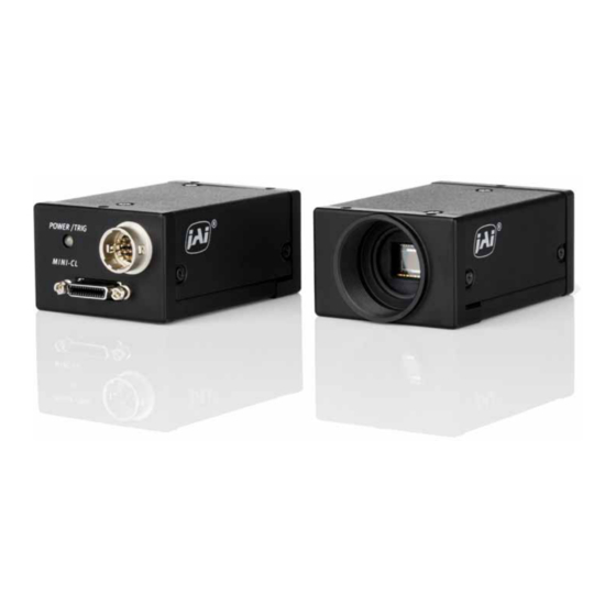
CMCB-140MCL/CM-140MCL-UV/CMCB-140PMCL 4. Locations and Functions 4.1. CM-140 MCL / CB-140 MCL Lens mount C-mount (Note *1) CCD sensor 1/2 inch CCD sensor 26-pin connector Camera Link Interface (Mini-CL) (Note 2) 12-pin connector DC+12V and trigger input ... -
Page 9: Cm-140 Pmcl / Cb-140 Pmcl
CMCB-140 MCL/CM-140MCL-UV/CMCB-140 PMCL 4.2. CM-140 PMCL / CB-140 PMCL Lens mount C-mount (Note *1) CCD sensor 1/2 inch CCD sensor 26-pin connector Camera Link Interface (Mini-CL) ( Note “2) 12-pin connector DC+12V and trigger input LED Indication for power and trigger input ... -
Page 10: Pin Assignment
CMCB-140MCL/CM-140MCL-UV/CMCB-140PMCL 5. Pin Assignment 5.1. 12-pin Multi-connector (DC-IN/Trigger) – MCL-version only Type: HR10A-10R-12PB-01 (Hirose) male. Use the part number HR10A-10P-12S for the cable side Pin no. Signal Remarks +12 V DC input Iris video Only for Continuous mode. TR=0 XEEN out Trigger in TI=1 (or Camera Link TI=0). -
Page 11: Digital Output Connector For Mini-Cl (Camera Link)
CMCB-140 MCL/CM-140MCL-UV/CMCB-140 PMCL 5.2. Digital Output Connector for Mini-CL (Camera Link) Type: 26-pin SDR connector (3M or Honda type) Mini-CL connector 5.2.1. CM-140 MCL / CB-140 MCL Pin No Name Note 1,13,14,26 DC GND 7(+),20(-) Serial Com. 8(-),21(+) 10(+),23(-) Reserve Fig.4. -
Page 12: Input And Output Circuits
Camera Link. Trigger signals and the serial camera control are feed directly through its own pairs. The 26-pin Mini-CL SDR connector pin assignment follows the Camera Link base configuration. For a detailed description of the Camera Link standard, please refer to the Camera Link standard specifications found on www.jai.com... -
Page 13: Functions And Operations
6. Functions and Operations 6.1. Basic functions The CMCB-140 MCL / CMCB-140 PMCL /CM-140MCL-UV/PMCL-UV cameras are progressive scan camera with 1.4 Mega pixels monochrome and Bayer mosaic color CCDs. The interface to the host PC is via digital Mini Camera Link (Mini-CL). Both models output video as 8 or 10 bits. The CB-140 MCL /PMCL outputs raw Bayer video, requiring host based color interpolation. -
Page 14: Electronic Shutter
CMCB-140MCL/CM-140MCL-UV/CMCB-140PMCL 6.1.2. Electronic Shutter The CM/CB-140 MCL ,CM/CB-140PMCL and CM-140MCL-UV/PMCL-UV allow selecting shutter speed in two ways; preset shutter (10 fixed steps) and programmable exposure (in 1051 line period, LVAL, increments). Preset Shutter The following shutter speeds can be selected by command SH=0 through SH=9. OFF (1/31), 1/60, 1/100, 1/250, 1/500, 1/1000, 1/2000, 1/4000, 1/8000, 1/10000 seconds Note: UV version is OFF (1/16), 1/30,1/60, 1/100, 1/250, 1/500, 1/1000, 1/2000, 1/4000, 1/10000 seconds Programmable Exposure (PE) -
Page 15: Auto-Detect Lval-Sync / Async. Accumulation
6.1.6. Auto-detect LVAL-sync / async. accumulation This function replaces the manual setting found in older JAI cameras. Whether accumulation is synchronous or a-synchronous in relationship to LVAL depends on the timing of the trigger input. When trigger is received while FVAL is high (during readout), the camera works in LVAL synchronous mode, preventing reset feed trough in the video signal. -
Page 16: Vertical Binning
CMCB-140MCL/CM-140MCL-UV/CMCB-140PMCL 6.1.8. Vertical Binning This function is only available on the CM-140MCL/-UV/PMCL/-UV camera. Binning mode (Command VB) is a function where the signal charge from 2 adjacent (vertical) pixels are added together and read out as one pixel. Binning results in half vertical resolution and higher frame rate. -
Page 17: Sensor Layout And Timing
CMCB-140 MCL/CM-140MCL-UV/CMCB-140 PMCL 6.2. Sensor Layout and timing 6.2.1. CCD Sensor Layout The CCD sensor layout with respect to pixels and lines used in the timing and video full frame read out is shown below. For Bayer color sequence, refer to chapter 6.1.3. -
Page 18: Horizontal Timing
CMCB-140MCL/CM-140MCL-UV/CMCB-140PMCL 6.2.2. Horizontal timing The LVAL period is shown for continuous mode. Model 1 LVAL 1 clock CMCB-140MCL/PMCL 1988 clks = 30.584 µs 15.38 ns CM-140MCL-UV/PMCL-UV 1988 clks = 58.9 µs 29.63 ns Fig. 16. Horizontal timing 6.2.3. Vertical timing The FVAL period for continuous mode full scan is shown. -
Page 19: Partial Scan
CMCB-140 MCL/CM-140MCL-UV/CMCB-140 PMCL 6.2.4. Partial Scan Partial scan allows higher frame rate by reading out a smaller center portion of the image. This is particularly useful when inspecting objects that do not fill the whole height of the image. Fast-dump period... -
Page 20: Vertical Binning
CMCB-140MCL/CM-140MCL-UV/CMCB-140PMCL Horizontal Timing The horizontal timing is the same the full scanning. Model 1 LVAL 1 clock CMCB-140MCL/PMCL 1988 clks = 30.584 µs 15.38 ns CM-140MCL-UV/PMCL-UV 1988 clks = 58.9 µs 29.63 ns Fig. 19. Horizontal timing for partial scanning 6.2.5. -
Page 21: Operation Modes
CMCB-140 MCL/CM-140MCL-UV/CMCB-140 PMCL Vertical timing Model Frame rate 527L CMCB-140MCL/PMCL 48.87fps CM-140MCL-UV/PMCL-UV 25.37fps LVAL FVAL 1037+1038 1039+1040 1+2 3+4 DVAL 520L Valid data DATA CCD Exposure XEEN Fig.21. Vertical Timing for Vertical Binning 6.3. Operation Modes This camera can operate in 3 primary modes. -
Page 22: Pre-Select Trigger Mode
CMCB-140MCL/CM-140MCL-UV/CMCB-140PMCL 6.3.2. Pre-select Trigger Mode An external trigger pulse initiates the capture, and the exposure time (accumulation time) is defined by the SH or PE commands. The resulting video signal will start to be read out after the selected shutter time. For timing details, refer to fig. - Page 23 CMCB-140 MCL/CM-140MCL-UV/CMCB-140 PMCL LVAL_async timing MCL/PMCL : 7.83 μs ± 1μs : 15.66 μs ± 1μs Trig 1L(min.) CCD exposure Exposure time XEEN FVAL Trigger input within FVAL LOW period 2L to 3L FLVAL a-sync mode etting MCL/PMCL : (Full:63μs ~94 μs) (V Binning:89μs ~126μs) : (Full:117.8μs ~176.7 μs) (V Binning:149.6μs ~224.4μs)
-
Page 24: Pulse Width Trigger Mode
CMCB-140MCL/CM-140MCL-UV/CMCB-140PMCL 6.3.3. Pulse Width Trigger Mode In this mode the accumulation time is equal the trigger pulse width. Here it is possible to have long time exposure. The maximum recommended time is <60 frames. For timing details, refer to fig. 16 through fig. 21 and fig. 24 & 25. To use this mode: Set function: Trigger mode to “Pulse width control”. - Page 25 CMCB-140 MCL/CM-140MCL-UV/CMCB-140 PMCL LVAL_async timing MCL/PMCL : 7.83μs ±1μs : 15.66μs±1μs Trig 1L(Min.) CCD exposure Exposure time XEEN FVAL When the trigger pulse is input while F VAL is low, the LVAL accumulation mode is LVAL async. 2L to 3L MCL/PMCL : (FULL:63μs ~ 94μs, V Binning:89μs ~ 126μs)
-
Page 26: Reset Continuous (Rct) Trigger Mode
CMCB-140MCL/CM-140MCL-UV/CMCB-140PMCL 6.3.4 Reset Continuous (RCT) trigger mode The RCT mode operates like EPS (edge preselect) mode with smearless function. An external trigger pulse will immediately stop the video read out, reset and restart the exposure, then operate as normal mode until the next trigger. After the trigger pulse is input, a fast dump read out is performed. -
Page 27: Mode And Function Matrix
CMCB-140 MCL/CM-140MCL-UV/CMCB-140 PMCL 6.4. Mode and function matrix. The following table shows which functions will work in the different modes for CM/CB-140MCL and CM/ CB-140PMCL. Shutter Partial Accumulation Iris Func. scan Binning video Trigger Mode Pre-select Programmable LVAL sync/async Cont. -
Page 28: Configuring The Camera
All configuration of the CM/CB-140MCL and CM / CB-140PMCL cameras are done via the serial communication in the Camera Link connector. The camera can be set up from a PC running terminal emulator software, or using JAI's camera control software. Below is the description of the ASCII based short command protocol. -
Page 29: Setting Functions
CMCB-140 MCL/CM-140MCL-UV/CMCB-140 PMCL 7.2. Setting functions 7.2.1. Bit allocation. BA=0, BA=1 This command sets the output for either 8-bit or 10-bit. 7.2.2. Partial scan. SC=0 through 4. The CCD scanning format can be selected between full or partial scanning. With partial scanning only the vertical central part of the CCD sensor is read out with a higher frame rate. -
Page 30: Cm/Cb-140Mcl / Cm/Cb-140Pmcl Command List
CMCB-140MCL/CM-140MCL-UV/CMCB-140PMCL Save Settings. SA. This command will store the actual camera settings to 1 of the 3 user area in the camera EEPROM. EEPROM Area. EA. If received, the camera will return the last used user area number. 7.4. CM/CB-140MCL / CM/CB-140PMCL command list Command Name Format Parameter... - Page 31 CMCB-140 MCL/CM-140MCL-UV/CMCB-140 PMCL Command Name Format Parameter Remarks D -Image Format BA=[Param.]<CR><LF> 0=10bit Bit Allocation BA?<CR><LF> 1=8bit 0=Full Frame 1=2/3 Partial SC=[Param.]<CR><LF> Scan Format 2=1/2 Partial SC? <CR><LF> 3=1/4 Partial 4=1/8 Partial VB=[Param.]<CR><LF> 0=OFF Only for CM- V-Binning VB?<CR><LF> 1=On...
-
Page 32: Camera Control Tool For Cm/Cb-140 Mcl / Cm/Cb-140 Pmcl
CMCB-140MCL/CM-140MCL-UV/CMCB-140PMCL 8. Camera Control Tool for CM/CB-140 MCL / CM/CB-140 PMCL The Camera Control Tool for Windows 2000/XP can be downloaded from www.jai.com. The control tool contains a camera control program and a developer's kit for integrating the control tool in your own software. For the integrator and experienced user, the Camera Control Toll is much more than a program with a window interface. -
Page 33: Communication Window
CMCB-140 MCL/CM-140MCL-UV/CMCB-140 PMCL The bar is red when the Camera Control Tool is not connected to a camera or when the camera is turned off. 8.3. Communication Window The Communication Window is used to connect the Camera Control Tool with the JAI camera. -
Page 34: Camera Control Window
3. It is possible to work with the Camera Control Tool when the camera is online and when the camera is offline. 4. The newer JAI cameras always start up with the last used user area (but for some old models it will start up with the last saved user area.) 5. - Page 35 CMCB-140 MCL/CM-140MCL-UV/CMCB-140 PMCL 7. When you turn on the camera and the Camera Control Tool, it is possible that the Camera Control Tool does not show the actual camera settings (see 4. and 5.). a. To obtain the camera settings click “Synchronize Program”.
-
Page 36: External Appearance And Dimensions
CMCB-140MCL/CM-140MCL-UV/CMCB-140PMCL 9. External Appearance and Dimensions 3-M3 depth 3.5 (0.2) (depth0.14) (2.28) (1.73) (2.60) POWER/ TRI G M I NI - CL C-Mount (1.97) (0.51) 6-M3 depth 3.5 (depth0.14) (0.2) Unit:mm ( ) :inch Outsi de si ze tol er ance:± 0. 3m m Fig. -
Page 37: Specifications
CMCB-140 MCL/CM-140MCL-UV/CMCB-140 PMCL 10. Specifications 10.1. Spectral response Fig. 30. Spectral response for CM-140MCL/PMCL IR Filter Wave Length [ nm ] Fig.31. Spectral response for CB-140MCL/PMCL... - Page 38 CMCB-140MCL/CM-140MCL-UV/CMCB-140PMCL Fig 32. Spectral response for CM-140MCL-UV/PMCL-UV...
-
Page 39: Specification Table(Cmb-140Mcl/Cmb-140Pmcl)
CMCB-140 MCL/CM-140MCL-UV/CMCB-140 PMCL 10.2. Specification table(CMB-140MCL/CMB-140PMCL) Specifications CM-140 MCL CB-140 MCL Scanning system Progressive scan 31.08 frames/sec. Progressive Frame rate full frame (1052 lines/frame) Pixel clock 65 MHz 32.681kHz Line frequency (1988 pixel clock/line) CCD sensor 1/2”. Monochrome ICX267AL 1/2” Color ICX-267AK Sensing area 6.4 (h) x 4.8 (v) mm... -
Page 40: Specification Table(Cm-140Mcl-Uv/Cm-140Pmcl-Uv)
CMCB-140MCL/CM-140MCL-UV/CMCB-140PMCL 10.3. Specification table(CM-140MCL-UV/CM-140PMCL-UV) Specifications CM-140 MCL-UV/CM-140PMCL-UV Scanning system Progressive scan 16.14 frames/sec. Progressive Frame rate full frame (1052 lines/frame) Pixel clock 33.75 MHz 16.978 kHz Line frequency (1988 pixel clock/line) CCD sensor 1/2” Monochrome UV sensitive ICX407BLA Sensing area 6.4 (h) x 4.8 (v) mm Cell size 4.65 (h) x 4.65(v) m... -
Page 41: Appendix
CMCB-140 MCL/CM-140MCL-UV/CMCB-140 PMCL 11. Appendix 11.1. Precautions Personnel not trained in dealing with similar electronic devices should not service this camera. The camera contains components sensitive to electrostatic discharge. The handling of these devices should follow the requirements of electrostatic sensitive components. -
Page 42: Caution When Mounting The Camera
When exporting this product, please follow the export regulation of your own country. 11.6. References 1. This manual for CM/CB-140 MCL / CM/CB-140 PMCL can be downloaded from www.jai.com 2. Datasheet for CM/CB-140 MCL / CM/CB-140PMCL can be downloaded from www.jai.com... - Page 43 CMCB-140 MCL/CM-140MCL-UV/CMCB-140 PMCL Index —A— —M— asynchronous ....3, 10, 11, 17, 19, 32 Mini-CL connector ....... 7 —B— —O— Bayer mosaic color ......3, 9 OCX ..........26 Binning mode........12 Bit Allocation......... 9, 25 —P— Black Level ........25 Partial scanning ....
-
Page 44: Change History
CMCB-140MCL/CM-140MCL-UV/CMCB-140PMCL Change History Month/Year Revision Changes June 2007 New release June 2008 Add PMCL version Sept 2009 Change the depth in chassis for screws from 4mm to 3.5mm and add caution, Add RCT trigger mode, Add UV version Feb 2010 Correct effective horizontal pixel number from 1380 to 1392. -
Page 45: Firmware Version
Company and product names mentioned in this manual are trademarks or registered trademarks of their respective owners. JAI A-S cannot be held responsible for any technical or typographical errors and reserves the right to make changes to products and documentation without prior notification.
Need help?
Do you have a question about the CMCB-140 MCL and is the answer not in the manual?
Questions and answers