
Related Manuals for JAI CV-L108CL


Summary of Contents for JAI CV-L108CL
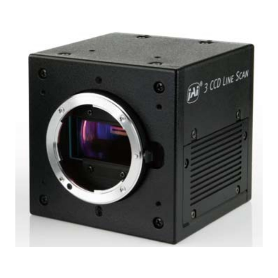
- Page 1 User's Manual CV-L108CL 3CCD High Speed Color Line Scan Camera Document Version: 1.2 CV-L108CL_V.1.2_Nov2010 1007E-0907...
- Page 2 JAI Ltd., Japan and may only be used by the purchasers of the product. JAI Ltd., Japan makes no warranty for the use of its product and assumes no responsibility for any errors which may appear or for damages resulting from the use of the information contained herein.
- Page 3 CV-L108CL Supplement The following statement is related to the regulation on “ Measures for the Administration of the control of Pollution by Electronic Information Products “ , known as “ China RoHS “. The table shows contained Hazardous Substances in this camera.
-
Page 4: Table Of Contents
Rear panel indicator ................20 Configuring the camera ................... 21 7.1. CV-L108CL Command list ................21 Functions listed alphabetically by command acronyms ..........25 Command AHRS – Request status after One-Push AWB ........25 Command AL – Automatic Line Rate Reference Level ......... 25 Command AR –... - Page 5 8.34 Factory default settings ................34 8.35 Serial communication ................35 Camera Control Tool for CV-L108CL ..............36 9.1 Control Tool Windows ................. 37 9.2 Camera Control Tool Interface ............... 38 9.3 Using Camera Control Tool ................40 10 External appearance and Dimensions ..............41 11 Specifications ....................
-
Page 6: General
1. General CV-L108CL is a 3CCD line scan camera using three 512 pixel line sensors mounted on a prism, for the R, G and B channels. It operates with a 40 MHz pixel clock, resulting in a maximum line rate of 70,922 lines per second. -
Page 7: Locations And Functions
CV-L108CL 4. Locations and functions Fig. 1 Location of external features 1 Camera Link base connector (1) (*Note) 2 Camera Link medium connector (2) (*Note) 3 12-pin Hirose connector for DC +12, External trigger and RS-232C LED indicator Orange, steady: Initializing or one-push operation... -
Page 8: Connectors
Cables, transmission systems and frame grabbers/acquisition boards that do not comply with the Camera Link standard may work with this camera, but JAI Camera Solutions cannot be held responsible for loss in performance or damage of equipment, including the camera. -
Page 9: Input And Output Circuits
11,24 12,25 13,26 Shield The CV-L108CL follows the Camera Link standard in all respects. Please refer to the Camera Link version 1.1 specifications for detailed information on bit assignments of 24-bit RGB and 30-bit bit output. 5.3. Input and output circuits 5.3.1. -
Page 10: Een / Xeen Output (Exposure Enable)
CV-L108CL 5.3.2. EEN / XEEN output (Exposure ENable) This output corresponds to the exposure (accumulation) time of the camera. It works together with all operation modes. It is, however, not active when the test pattern function is enabled. The EEN signal is available at the Camera Link connector and at the 12-pin Hirose connector at the same time. -
Page 11: Functions And Operation
(the inverse of line rate). This also allows a fixed exposure time, independent of the line rate. In the CV-L108CL the exposure time can be set individually for all three channels. -
Page 12: Pixel Gain (Flat-Field) Correction (Prnu Correction)
CV-L108CL 6.2. Pixel Gain (flat-field) correction (PRNU correction) Pixel Response Non-Uniformity is, as the name expresses, a non-uniformity of the response of each individual pixel. This means that for a fixed light level each pixel will have a slightly different output level (response). -
Page 13: Shading Correction
CV-L108CL After correction: Flat dark signal response from pixel to pixel Average 6.4. Shading correction Shading is caused either by illumination with uneven distribution of light across the surface, or by vignetting towards the edges of a lens. The shading correction incorporated in the camera will compensate for this effect by as much as 20% of the brightest signal. -
Page 14: Operation Modes
6.6. Operation modes The CV-L108CL provides three basic modes of operation: No-shutter, Shutter-Select and Pulse Width Control (PWC). The Shutter-Select and PWC modes also allow the user to set the exposure time independently from the scan rate, by making use of the electronic shutter (the Exposure Control Gate of the CCD sensor). -
Page 15: No-Shutter Mode With Internal Line Rate Generator
CV-L108CL 6.6.1. No-Shutter mode with internal line rate generator In this mode the camera does not accept an external trigger signal, as the line rate is generated from an internal clock (user programmable, command LR). The exposure time is directly proportional to the line rate (T = 1/line rate). -
Page 16: No-Shutter Mode With External Trigger
CV-L108CL 6.6.2. No-Shutter mode with external trigger In this mode, the exposure time is directly proportional to the line rate. The line rate is generated externally by a trigger signal. This mode is used when an external trigger signal is available, e.g. -
Page 17: Shutter-Select Mode With Internal Line Rate Generator
CV-L108CL 6.6.3. Shutter-Select mode with internal line rate generator This mode allows the user to have full control of the line rate and the exposure time individually, by programming separate timing generators. Subsequently the camera does not accept an external trigger signal in this mode. -
Page 18: Shutter-Select Mode With External Trigger
CV-L108CL 6.6.4. Shutter-Select mode with external trigger This mode allows the user to have full control of the exposure time, by programming a timing generator, while the line rate is controlled by an external trigger signal. The camera can accept an external trigger through the Camera Link connector or though the 12-pin Hirose connector. -
Page 19: Pulse Width Control (Pwc) Mode
CV-L108CL 6.6.5. Pulse Width Control (PWC) mode In this mode, the user has full control of both the line rate and the exposure time of each line via the External Trigger input. At the falling edge of the External Trigger signal, the exposure is initiated, and at the rising edge the exposure is terminated and read out. -
Page 20: Auto Reset Mode
6.6.6. Auto Reset mode In this mode, when the interval of the trigger pulse is more than 55ms, the CV-L108CL automatically returns to continuous operation with the line rate of 14.10μs . At this time, DVAL and Video OUTPUT are disabled in order to prohibit charge due to dark current to add up in the sensor in standby periods. -
Page 21: Relationship Between Trigger And Lval
CV-L108CL 6.8. Relationship between Trigger and LVAL Trigger and LVAL mode Mode Trigger Relations No-Shutter Internal Synchronous External Shutter-Select Synchronous Internal External Asynchronous External Asynchronous 6.9. Compatibility of trigger modes and functions Functions Trigger Binning Pixel gain Shading One-Push WB Gain &... -
Page 22: Configuring The Camera
Link connector or via RS-232C on the Hirose 12-pin connector. Chapter 7.1 shows the complete list of ASCII commands. Chapter 7.2 describes the commands in detail, in alphabetical order (sorted by command the acronym) 7.1. CV-L108CL Command list Command Format Parameter... - Page 23 CV-L108CL Programmable PEG=[Param.]<CR><LF 2 to 577536, in 25ns Exposure > Only valid for TR=1 increments Green PEG?<CR><LF> Programmable PEB=[Param.]<CR><LF 2 to 577536, in 25ns Exposure > Only valid for TR=1 increments Blue PEB?<CR><LF> One-push AWB 0=Activate one-push AWB AH=[Param.]<CR><LF> Only valid for TR=1...
- Page 24 CV-L108CL Black Level - BLB=[Param.]<CR><LF> -64 to 63 Blue BLB?<CR><LF> 0=Manual/One push AWB WB=[Param.]<CR><LF> 1=4000K White Balance WB?<CR><LF> 2=4600K 3=5600K Activate AW=[Param.]<CR><LF> 0=Activate one-push AWB One-push AWB <Camera replies > 0=AWB has not been finished yet. 1=Succeeded. Inquire the 2=Error1. Green image was...
- Page 25 CV-L108CL shading 1=Succeeded. correction 2=Error1 - Timeout error occurred. Select pixel 0=Off (Bypass) gain PGC=[Param.]<CR><LF> 1=Factory area Only valid for SHC=0. correction PGC?<CR><LF> 2=User area mode Run pixel gain 0=Run pixel gain correction, PGR=[Param.]<CR><LF> correction, store to user Store in user setting.
-
Page 26: Functions Listed Alphabetically By Command Acronyms
CV-L108CL Functions listed alphabetically by command acronyms Command AHRS – Request status after One-Push AWB This command returns the status of the One-Push AWB function, with the following parameters: 0=AWB not completed yet 1=Succeeded 2=Error1: Green image too bright 3=Error2: Green image too dark 4=Error3: Timeout occurred Command AL –... -
Page 27: Command Ah - Activate One-Push Auto White Balance (Awb) - Shutter
CV-L108CL Important Note: When color temperature of used illumination exceeds the range of adjustment, proper white balance may not be obtained. The data can be stored in camera memory for use at next start up. This function can work on external trigger mode. -
Page 28: Command Bl - Master Black Level
CV-L108CL Command BL – Master Black Level This command is a global black level adjustment for all channels. The adjustable range for master black is 0LSB to 64 (16) LSB. The number in parenthesis is valid for 24-bit output. Settings:... -
Page 29: Commands Ksr, Ksg And Ksb - Knee Slope For R, G And B
CV-L108CL the details above 1023 are not visible. This function changes the gain signal from CCD over 100% video output level and compress signal up to 4095 LSB. The knee point is the upper limit of linear relations between CCD output and input to Camera Link. The knee slope decides how much of the signal above 100% video output is compressed. -
Page 30: Command Pbc - Enable Pixel Black (Fpn) Correction
CV-L108CL 8.19 Command NOSR – Noise reduction This function deletes the noise component of less than 16LSB composed in the signal. This circuit used in the CV-L107CL minimizes the deterioration of the spatial frequency. The improvement depends on the object and it will be approx. 3dB. -
Page 31: Command Peb - Programmable Exposure - Blue
CV-L108CL 8.24 Command PEB – Programmable exposure – Blue This command allows individual setting of the exposure time of the Blue channel. It is only valid for the Shutter-Select mode (see chapter 6.2) Settings: 2 to 577536, 50 ns to 14.438 ms in 25ns steps... - Page 32 CV-L108CL The calculation is based on the average value of 8 consecutive pixels. The maximum deviation that can be compensated is -20% of the highest signal level (brightness) of the line. Individual shading correction per channel Important note: Depending on the optics and/or illumination used together with the camera, it may not be possible to fully compensate for shading.
-
Page 33: Command Sds - Request Status After Executing Shading Correction Command
CV-L108CL 8.29 Command SDS – Request status after executing shading correction command This command returns the status of the shading correction function, with the following parameters: 0=Shading correction not completed yet 1=Successful 3=Error1 – Timeout occurred 8.30 Command TG – Trigger Origin Selects whether an external signal or an internal clock generator is used as a trigger source. -
Page 34: Command Ts - Test Pattern
CV-L108CL 8.34 Command TS – Test pattern This allows the camera to output a number of test patterns for set-up and troubleshooting. Settings: 0=off 1=Color bar 2=Gray wedge 3=Gray bars 4=White (890LSB) Signal 32 (8) 10bit (8-bit) Pixel count Fig. 16 Color bar test pattern... -
Page 35: Command Wb - White Balance
CV-L108CL 890 (222) 10bit (8-bit) Signal (RGB) 32 (8) 10bit (8-bit) Pixel count Fig. 19 White level test pattern 8.35 Command WB – White Balance The white balance function can be used for manual setting, One-Push automatic white balance (AWB) and fixed color temperatures (3 selections) -
Page 36: Serial Communication
8.37 Serial communication The CV-L108CL can communicate by serial communication via the Camera Link connector or via RS232C in the 12-pin Hirose connector. The Baud Rate is fixed at 9600 bps. Switch SW1 at the rear panel of the camera is used to select which way the serial communication is set up. -
Page 37: Camera Control Tool For Cv-L108Cl
ID?<CR><LF> 9 Camera Control Tool for CV-L108CL From www.jai.com a Camera Control Tool for Windows 2000/XP/Vista can be downloaded. The control tool contains a camera control program and tools for making your own program. For the integrator and experienced user, the Camera Control Tool is much more than a program with a window interface. -
Page 38: Control Tool Windows
CV-L108CL 9.1 Control Tool Windows... -
Page 39: Camera Control Tool Interface
The About window The about window contains a picture of the camera and information about the version of the program, Internet connection to JAI A/S and access to the help documents. The List box that contains the help documents will list all files. - Page 40 CV-L108CL RS-232 communication: 1. Select ‟COM-ports‟ from the ‟CL Manufacturer/COM-ports‟ list Box. 2. Select the communication port, where the serial cable is connected to the camera from the ‟Serial Port‟ list box or click the „Auto‟ button to search for a camera on communication port 1 to 16.
-
Page 41: Using Camera Control Tool
3. It is possible to work with the Camera Control Tool when the camera is online and when the camera is offline. 4. The newer JAI cameras always start up with the last used user area (but for some old models it will start up with the last saved user area.) 5. -
Page 42: External Appearance And Dimensions
CV-L108CL 10 External appearance and Dimensions 4- M3 depth5 ( depth 0. 20) ( 7) 25. 5 +0. 012 φ 4 depth3. 5 ( 0. 28) ( 1. 00) ( depth0. 14) 32. 5 ( 2. 36) ( 1. 28) U4- 40: Fi xed scr ew ( 3. -
Page 43: Specifications
CV-L108CL 11 Specifications 11.1 Typical data Scanning system Line Scan Pixel clock 40.00 MHz Line rate: 14.10 μs (No-Shutter mode with Internal trigger) Line Rate Line Frequency: 70.922 kHz ( Standard ) (total number of pixels per line: 564 Programmable line Adjustable range: 14.10 μs(1L) to 14.438 ms(1024L) - Page 44 CV-L108CL Sync output Camera link LVAL, DVAL, EEN (open termination) Hirose 12Pin XEEN (Negative logic) 4.0 Vp-p (no termination) Via Camera Link connector or RS-232C (Hirose 12-Pin connector) Communication Baud rate : 9600bps interface Interface is switched by SW1 located rear panel.
-
Page 45: Spectral Sensitivity
CV-L108CL 11.2 Spectral sensitivity Fig. 21 Spectral Response... -
Page 46: Appendix
Remove power from the camera when changing switch settings. 12.2 Typical Sensor Characteristics The image sensors used in the CV-L108CL have been chosen for their superior performance. There may, however, always be artifacts visible in the scanned image originating from pixel imperfections in the camera. -
Page 47: Change History
CV-L108CL Change History Month/Year Revision Changes July 2009 New release Nov.2010 Correct the video timing on the figure 8. Add GAR2,GAB2 and NOSR in the command list in Chapter 7.1. Add the descriptions for GAR2 and GAB2 in Chpter 8.14 and NOSR in the Chapter 8.19. -
Page 48: User's Record
Company and product names mentioned in this manual are trademarks or registered trademarks of their respective owners. JAI A-S cannot be held responsible for any technical or typographical errors and reserves the right to make changes to products and documentation without prior notification.
Need help?
Do you have a question about the CV-L108CL and is the answer not in the manual?
Questions and answers