
Related Manuals for JAI CV-M90


Summary of Contents for JAI CV-M90
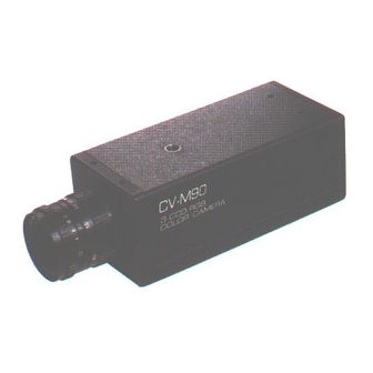
- Page 1 3CCD RGB Color Camera Operation Manual Applicable only for serial No. NTSC : N900601 ~ : P900601 ~...
- Page 2 ENGLISH VERSION RISK OF ELECTRIC SHOCK DO NOT OPEN CAUTION: TO REDUCE THE RISK OF ELECTRIC SHOCK, DO NOT REMOVE COVER (OR BACK), NO USER SERVICEABLE PARTS INSIDE. REFER SERVICING TO QUALIFIED SERVICE PERSONNEL. The lighting flash with arrowhead symbol, within an equilateral triangle, is intend to alert the user to the presence of uninsulated ”dangerous voltage”...
- Page 3 Precautions Do not attempt to disassemble this camera. To prevent electric shock, do not remove cover. There are no user- serviceable parts inside. Refer servicing to qualified service personnel. Do not expose this camera to rain or moisture. Do not face this camera towards the sun, extreme bright light or light reflecting objects.
-
Page 4: Typical Ccd Characteristics
Typical CCD Characteristics The following effects may be observed on the video monitor screen do not indicate any fault of the CCD camera, but do associate with typical CCD characteristics. V. Smear Due to an excessive bright object such as electric lighting, sun or strong r e f l e c t i o n , vertical smear may be visible on the video monitor screen. -
Page 5: Table Of Contents
Table of Contents 1. General..................... 3. Standard Composition ..............3. Main Features ................4. Locations and Functions............... 5. Pin Assignment 5-1. 12P Multi connector ............5-2. 6P Multi connector ............5-3. 9P D.sub connector ............6. -
Page 6: General
1. General CV-M90 (Rev.c) is a 3CCD RGB color camera exclusively designed for machine vision and image processing applications where excellent reso- lution, high fidelity color-reproduction and advanced electronic shutter capability are required. 3CCD C-mount optical prism block is newly developed in ultra-compact... -
Page 7: Main Features
3. Main Features 3 x 1/3” Hyper HAD Interline transfer CCD imager, 768(H) x 494(V) for NTSC and 752(H) x 582(V) for PAL Co-site sampling for higher quality color image required in machine vision and image processing applications Ultra-compact RGB prism for C-mount High resolution - horizontal 570 TV lines Excellent S/N - better than 56 dB RGB &... -
Page 8: Locations And Functions
4. Locations and Functions CCD Sensor : 1/3“ Hyper HAD Interline transfer CCD sensor Lens mount : C-mount type Note: Rear protrusion (screw part) of C-mount lens must be less than 4.1mm (0.16 inch approx.) SW1 switch : To set the shutter speed and function modes 9-pin Dsub connector : Output RGB Video signal and Sync. -
Page 9: Pin Assignment
5. Pin Assignment 5-1. 12P Multi Connector (DC IN/SYNC) HR10A-10R-12PB-01 (Hirose) Ext. Trigger mode Pin no Ext. Int. HD/VD input Mode Random Random Long Time HD/VD output mode (Factory Pre-set) Trigger-1 Trigger-2 Exposure DC+12V input DC+12V input DC+12V input Ext HD input (75 Ω Ω Ω Ω Ω ) Ext HD input (75 Ω... -
Page 10: Multi Connector
5-2. 6P Multi Connector (TRIGGER) HR10A-7R-6P (Hirose) Ext. trigger mode Random trigger mode-1 Random trigger mode-2 pin no. (Factory Pre-set) TXD Output TXD Output RXD Input RXD Input EEN pulse output EEN pulse output Ext. Trigger input (75 Ω Ω Ω Ω Ω ) Ext. -
Page 11: D.sub Connector
5-3. 9P D.sub Connector 09K0320-180 (Waka) Pin no Ext. Trigger mode Ext. HD/VD input Int. HD/VD output Random Random Long Time (Factory Pre-set) Trigger-1 Trigger-2 Exposure R output R output R output G output G output G output B output B output B output Ext HD input (75 Ω... -
Page 12: Functions And Operations
6-1. Input/Output of HD/VD signal a) Input of External HD/VD signal (Factory Pre-set) Video output of CV-M90(rev.c) in factory pre-set mode can be synchronized with external HD/VD signal (4.0Vp-p ± 2.0V at 75 Ω Ω Ω Ω Ω terminated) . -
Page 13: A) Random Trigger Mode - 1
Random Trigger Mode - 1 In Random Trigger Mode-1 (only in Non-interlaced, field accumulation mode), CV-M90(rev.c) starts an exposure (=accumulation of electric charge) at the falling edge of ext. trigger pulse and ends the exposure according to the time set by shutter (7-step fixed shutter speed), and outputs the accumulated signal in one-field (odd-field in EIA and even-field in CCIR). - Page 14 Caution on Random Trigger Mode-1 Random trigger mode-1 is effective only at Non-interlaced, field accumulation mode. 1H jitter max. may occur when ext. trigger and Int. HD signals are not synchronized each other. Therefore, It is recommended to make phase- synchronization between ext.
-
Page 15: B) Random Trigger Mode - 2
In this mode-2, the exposure time of shutter can be controlled within a range of 1/77 ~ 1/10,000sec. by a duration between ext. trigger pulse and ext. VD signal. CV-M90(rev.c) starts the exposure (=accumulation of electric charge) at falling edge of ext. - Page 16 Caution on Random Trigger Mode-2 As the Input of ext. VD signal must be given continuously to synchronize with int. VD signal it is not possible to input ext. VD signal ”at random”. Exposure-start may deiay up to 1H max., when the falling edge of ext. trigger pulse is not synchronized with the falling edge of ext.
-
Page 17: C) Long Time Exposure Mode
In Long Time Exposure mode, the exposure time of shutter can be controlled by a duration of ext. VD signal input. CV-M90(rev.C) starts the exposure (=accumulation of electric charge) after input of ext. VD signal, and ends the exposure after the next input of ext. VD signal. The accumulated video... - Page 18 Caution on Long Time Exposure Mode Theoretical exposure time of shutter in each TV standard is as follows. − ∞ − ∞ : 1/30sec. − ∞ − ∞ − ∞ − ∞ − ∞ : 1/25sec − ∞ − ∞ −...
-
Page 19: Mode Setting
7. Mode Setting Caution on Mode Setting Before making any mode setting such as switch and jumper setting, put the power „OFF“. 7-1. SW1 Switch on the rear panel Factory settings are made on the SW1 rear panel switch as below Switch Function Setting mode Shutter data 2SB... - Page 20 <SW1-1 SW1-3> 1/60 sec. : To select shutter speed, refer to the list as below. 1/10000 sec. SW1-1 SW1-2 SW1-3 Shutter speed (sec.) Normal shutter Ext Trigger Shutter 1/60 1/100 1/125 1/250 1/500 1/1000 1/2000 1/4500 1/10000 Caution on Electronic Shutter Under certain unique lighting conditions, the following may appear.
-
Page 21: Other Switches/Jumpers On Board
7-2. Other switches / jumpers on board From Top PK8088 board : SW301 switch and jumpers are located on this board. PK8061 board : Slide switch SW603 is located on this board. PK8087 board : Slide switch SW101 and potentiometers are located on this board. - Page 22 b) Jumper setting for input/Output of HD/VD signal To change HD/VD signal Int. or Ext., set the jumper as follow. Int. HD/VD output Int. HD/VD output Jumper (Factory Pre-set) JP305 Short Open JP306 Open Short JP308 Short Open JP309 Short Open c) Jumper setting for output of Sync./WEN To change the autput of Sync.
- Page 23 SW603 slide switch (Ext./Int. VD signal) on PK8061 board SW603 switch located on PK8061 board, is to select change pin assignment of pin no.1 of D-SUB 9pin connector. When it is set at OFF side, int. VD can be output or ext. VD can be input at pin no.1 of D-SUB 9pin connector.
- Page 24 SW101 slide switch (Sync. on Green) and potentiometers on PK 8087 board a) SW101 switch SW101 switch located on PK8087 board is to change the output of pin no. 4 of D.sub 9pin connector. At factory pre-set, Green signal is ouput from pin no.4. To output Sync.
- Page 25 SW201 slide switch (CCD Iris) and SW202 slide switch (One Push White Balance) on PK 8089 board a) SW201 switch SW201 switch located on PK8089 board is to ON/OFF the CCD Iris. At factory pre-set, it is set at OFF position. To use CCD Iris, make the following procedure.
- Page 26 For manual adjustment of White balance, adjust B/R Gain pot. located on rear panel. For One-Push white balance, set SW202 switch at ON position and push the One Push White Balance Switch located on rear panel. - PK8089 board sideA - 21 -...
-
Page 27: External Appearance
8. External Appearance Unit: mm (inches) - 22 -... -
Page 28: Specifications
9. Specifications TV Standard NTSC CCD Sensor 1/3” Hyper HAD Interline transfer CCD Effective no. of pixel 768 (H) x 494 (V) 380,000 pix.approx. 752 (H) x 582 (V) 440,000 pix. approx. Cell size 6.35 µ m(H) x 7.40 µ m(V) 6.50 µ...
Need help?
Do you have a question about the CV-M90 and is the answer not in the manual?
Questions and answers