
Subscribe to Our Youtube Channel
Related Manuals for JAI CV-M2


Summary of Contents for JAI CV-M2
- Page 1 Digital Monochrome 2 Megapixel Progressive Scan Camera CV-M2 Operation Manual Camera: Revision A Manual: Version 1.0 M2ManualJul22.doc JPT 22-07-03...
-
Page 2: Table Of Contents
7.2. RS-232C/Camera Link switch...26 7.3. Internal Switch ...26 7.4. RS-232C control ...27 7.5. CV-M2 command list ...28 7.6. Camera Control Tool for CV-M2...29 8. External Appearance and Dimensions ... 30 9. Specifications ... 30 9.1. Spectral sensitivity ...30 9.2. Specification table...31 10. -
Page 3: General
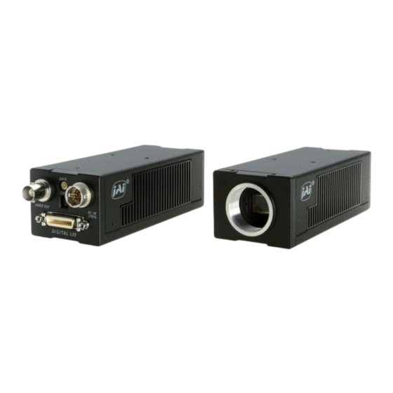
1. General The CV-M2 is a digital 2 megapixel camera designed for automated imaging and ITS (Intelligent Traffic Systems) applications, featuring high resolution and high speed within a uniform and compact housing. The high-speed shutter function, asynchronous random trigger mode and partial scan mode allows the camera to capture high quality images of fast moving objects with a high frame rate. -
Page 4: Locations And Functions
4. Locations and Functions 1. CCD sensor 2. Lens mount (C-mount) 3. Rear panel with SW1 4. Digital output connector (Camera Link) 5. DC in/Trigger in/RS-232C connector 6. BNC connector for monitor video output 7. Gain potentiometer 8. Mounting holes M3. (8x) Fig. -
Page 5: Pin Assignment
5. Pin Assignment 5.1. 12-pin Multi-connector (DC-IN/Trigger) Type: HR10A-10R-12PB-01 (Hirose) male. (Seen from rear of camera.) Fig. 2. 12-pin connector. 5.2. BNC connector for analogue monitor video output On the BNC connector an analogue video signal (CCIR or EIA) for monitoring is found if OS=2. The signal can be viewed on a standard monitor as 50 FPS/15.734 kHz 290 lines if MN=1, or 60 FPS/15.734 kHz 240 lines if MN=0. -
Page 6: Input And Output Circuits
5.4. Input and Output Circuits 5.4.1. Monitor video output On the BNC connector an analogue video signal for set-up is found if OS=2. The signal can be used for focus and field of view adjust. CCIR if MN=1. (50 fps, 17.734 kHz, 290 active lines.) EIA if MN=0. -
Page 7: Camera Link Interface
CL by an internal switch HR/CL. Refer to 7.2 The 26 pin MDR connector pin assignment follows the Camera Link base configuration. For a detailed description of Camera Link specifications, please refer to the Camera Link standard specifications found on CV-M2 Camera CV-M2 Camera Camera Signals Camera Signals... -
Page 8: Functions And Operations
6. Functions and Operations In the following the format shown in “7.5. CV-M2 command list” are used for function commands and parameters. 6.1. Basic functions The M2 camera is a progressive scan camera with 10 or 8 bit video output in single or dual channel Camera Link. -
Page 9: Restart Continuous Trigger Mode
6.1.3. Restart continuous trigger mode The RCT mode makes it possible to use a lens with video controlled iris for intelligent traffic surveillance applications. TR=2. The camera is running continuously, and the iris is controlled from the iris video output. When a trigger pulse is applied, the scanning is reset and restarted, the previous signal is dumped with a fast dump read out, and the new triggered exposure is started. -
Page 10: Sensor Gate Control
6.1.5. Sensor Gate Control This function is for applications where a strobe flash is the only illumination, and where the exact time for the strobe firing is not known. The time window for the strobe firing can be up to several frames. -
Page 11: Digital Video Out Allocation
6.1.6. Digital video out allocation The set-up and the relations between the analog and digital video are shown in fig. 13. [LSB] [LSB] video out video out 1023 1023 0 25 0 25 6.1.7. Knee function. The knee functions can compress the signals in the highlighted areas. The slope over the knee point is only 20%. -
Page 12: Sensor Layout And Timing
6.2. Sensor layout and timing. 6.2.1. CCD sensor layout The CCD sensor layout with respect to pixels and lines as it is used in the timing and video read out is shown below. D um m y & Bl ank Si ngl e O ut put D um m y &... -
Page 13: Horizontal Timing Single Channel
6.2.3. Horizontal timing single channel OS=0. Normal mode. Full frame. LVAL FVAL R ai si ng Edge FVAL SU B 444ck 958ck Exposur e Per i od m i n: 1. 5L( 1916+958ck) 54ck R eser ved 16ck 34ck D ATA O U T D VAL C C D O ut 6.2.4. -
Page 14: Horizontal Timing Dual Channel
6.2.5. Horizontal timing dual channel OS=1. Normal mode. Full frame. LVAL FVAL R ai si ng Edge FVAL SU B 32ck Exposur e Per i od m i n: 1. 5L( 1092+546ck) 54ck R eser ved 34ck 16ck D ATA O U T ( L ch) D ATA O U T ( R ch) -
Page 15: Lval Synchronous Accumulation
6.2.7. LVAL synchronous accumulation With LS=0, the accumulation will start synchronously with LVAL. The trigger pulse should be longer than 2 LVAL intervals, and the accumulation will then start at the first LVAL after the trigger leading edge. The exposure start delay will be up to 1 line. (Single channel 47.9 µsec. Dual 27.3 µsec). -
Page 16: Lval A-Synchronous Accumulation
6.2.8. LVAL a-synchronous accumulation With LS=1, the accumulation will start immediately after the trigger leading edge. The exposure start delay will be 156 clk. pulses after the trigger. It is 3.9 µsec. In EPS mode the exposure stops 0.5 L after the selected shutter time, (in number of LVAL). In PWC mode the exposure stops 0.5 L after the trigger trailing edge. -
Page 17: Partial Scanning Vertical Timing
6.2.9. Partial scanning vertical timing Partial scanning has 3 pre-selected vertical centred areas 1/2, 1/4 and 1/8. SC=1 through SC=3. With SC=3, the start and the height of the partial scanned area can be programmed with 1 line interval. The start line can be programmed with PS=1 through 1151. The scanned height can be programmed with PC=50 though 1200. -
Page 18: Input/Output Of Timing Signals
See the full connector pin assignment for Camera Link in chapter 5.3 and 5.4.5 For complete documentation on the Camera Link standard, please contact your JAI distributor. EEN is also found as a TTL signal on pin #9 on the 12 pin Hirose. EEN is low during exposure. -
Page 19: Continuous Operation (Non Triggered)
6.4.1. Continuous Operation (Non triggered) Mode settings can be done with RS-232C. Trigger Mode Normal. TR=0. It is for applications where the camera is continuously running without external trigger. The shutter mode can be normal or programmable exposure. (SM=0, SM=1). The shutter will work in all 10 steps up to 1/14,000 second or with the programmable exposure in 1216 steps. -
Page 20: Edge Pre-Select Mode
6.4.2. Edge Pre-select Mode In EPS mode, the trigger leading edge will start an exposure at the first LVAL pulse if LS=0, (or immediately if LS=1), and it stops and the resulting image is read out after the pre-selected shutter time. It can be the 10 steps in normal or 1216 steps in programmable. SM=0 or SM=1. This mode will operate with full and partial scanning. -
Page 21: Restart Continuous Trigger Mode
6.4.3. Restart Continuous Trigger mode The RCT mode is in principle the same as normal continuous mode. The difference is that an external trigger pulse will immediately stop the video read out and reset and restart the vertical timing. After a fast dump read out, a new triggered exposure is started and read out as normal. The fast dump read out is performed with a speed 18 times faster for single output, and 10 times faster for dual output. -
Page 22: Pulse Width Control Mode
6.4.4. Pulse Width Control Mode In PWC mode, the trigger leading edge will start an exposure at the first LVAL pulse if LS=0 (or immediately if LS=1). It stops at the trailing edge of the trigger pulse, and the resulting video is read out. -
Page 23: Burst Trigger Mode
6.4.5. Burst Trigger mode With the burst trigger function, a single trigger pulse can start a sequence with five previous set pre-selected programmable exposures. The five shutter times can be set with BSH1 through BSH5. (Exposure 1H through 1216H.) The exposure is LVAL synchronous. The sequence will start with the first exposure at the first LVAL pulse after the trigger leading edge, and the result is read out after the selected shutter time. -
Page 24: Piv Mode
6.4.6. PIV mode. PIV mode (Particle Image Velocimetry) can be used in applications where 2 images should be taken with a very short time interval. It can only be used with strobe flash as illumination. The first accumulation time is fixed at 4 µsec. After a delay >1.5 µsec. the second exposure period starts. -
Page 25: Sensor Gate Control
6.4.7. Sensor Gate Control This function is for applications with strobe flash illuminations or long time accumulations up to several frames. The resulting video is then read out after the first FVAL (or SG), following the trailing edge of the Sensor Gate Control signal. The sensor gate control signal can be synchronized by the FVAL signal. -
Page 26: Other Functions
CV-M2 6.5. Other Functions. The following functions are described under their short ASCII command name. BA: Output bit allocation With this function the number of bits in the Camera Link video output can be selected to 10 or 8. If 8 bit is selected it is the 8 most significant bits. For the bit allocation in Camera Link output, please refer to “5.4.5. -
Page 27: Configuring The Camera
7. Configuring the Camera 7.1. Mode setting SW1 on rear Switch SW 1.1 on the camera rear can be used to select digital or analogue video out. SW1.1 has higher priority than RS-232C. SW1.2 is for termination of the trigger 1 input on pin #10 Hirose. (SW1.3 is for termination of the factory test input on pin #11 Hirose) SW1.4 is for master gain selection. -
Page 28: Rs-232C Control
7.4. RS-232C control All configuration of the CV-M2 camera is done via the RS-232C port on the 12 pin HR connector or via Camera Link. The control mode can be selected by the internal switch RS-232C/Camera Link. The camera can be set up from a PC running terminal emulator software, or using JAI´s camera control software. -
Page 29: Cv-M2 Command List
7.5. CV-M2 command list Command Name A – General settings and useful commands Echo Back Camera Status request Online Help request Firmware version Camera ID request Model Name request User ID B – Video Output Output select Output bit allocation Monitor mode C –... -
Page 30: Camera Control Tool For Cv-M2
CV-M2 7.6. Camera Control Tool for CV-M2 From www.jai.com Camera Control Tool for Windows 98/NT/2000 can be downloaded. The control tool contents a camera control program and tools for making your own program. For the integrator and experienced user, the Camera Control Toll is much more than a program with a window interface. -
Page 31: External Appearance And Dimensions
8. External Appearance and Dimensions 9. Specifications 9.1. Spectral sensitivity Fig. 38. Outline. Wave lenght (nm) Fig. 39. Spectral sensitivity for M2. - 30 -... -
Page 32: Specification Table
Humidity Storage temp/humidity Power Lens mount Dimensions Weight CV-M2 Progressive 1216 lines 17 frames/sec. 40.00 MHz 20.88 kHz (1916 pixel clock/line). (H = 47.9 µsec) 36.63 kHz (1092 pixel clock/line). (H = 27.3 µsec) 17.17 frames/sec. (1216 lines/frame) 30.12 frames/sec. (1216 lines/frame) 1”... -
Page 33: Appendix
CV-M2 10. Appendix Precautions Personnel not trained in dealing with similar electronic devices should not service this camera. The camera contains components sensitive to electrostatic discharge. The handling of these devices should follow the requirements of electrostatic sensitive components. Do not attempt to disassemble this camera. -
Page 34: Declaration Of Conformity
Company and product names mentioned in this manual are trademarks or registered trademarks of their respective owners. JAI A-S cannot be held responsible for any technical or typographical errors and reserves the right to make changes to products and documentation without prior notification. - Page 35 CV-M2 - 34 -...
Need help?
Do you have a question about the CV-M2 and is the answer not in the manual?
Questions and answers