
Related Manuals for JAI CV-A1


Summary of Contents for JAI CV-A1
- Page 1 Compact Monochrome Megapixel Progressive Scan Camera CV-A1 Operation Manual Camera: Revision B Manual: Version 1.2 A1manB12oct08.doc JPT 08-10-03...
-
Page 2: Table Of Contents
6.11. Other Functions... 17 7. Configuring the Camera ... 17 7.1. RS-232C control..17 7.2. CV-A1 RS-232C command list..18 7.3. Camera Control Tool for CV-A1... 19 7.4. Internal Switch and Jumper Settings ... 20 8. External Appearance and Dimensions ... 20 9. -
Page 3: General
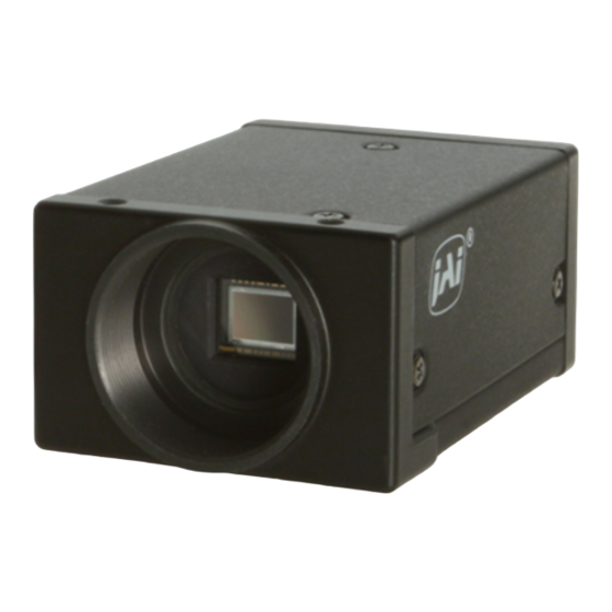
1. General The CV-A1 is a monochrome progressive scan 1/2” CCD camera with 1.4 Megapixel resolution. It is designed for automated inspection, featuring a small housing and a wide range of unique functions. The asynchronous trigger can be set to work in several modes, to allow such functions as pulse width controlled shutter, programmable shutter speed and long time integration. -
Page 4: Locations And Functions
4. Locations and Functions 12 pin Hirose connector for frame grabber interfacing and power (12V DC). BNC connector for video output. VS 1.0 Vpp 75 Ohm. 6 pin Hirose connector for trigger input and RS-232C control interface. Gain potentiometer for manual gain setting. Mounting holes, 8 x M3. -
Page 5: Pin Assignment
5. Pin Assignment 5.1. 12-pin Multi-connector (DC-IN/VIDEO OUT, EXT.HD/VD IN) Type: HR10A-10R-12PB-01 (Hirose) male Seen from rear Fig. 2. 12-pin connector. 5.2. 6-pin Multi-connector (TRIGGER) Type: HR10A-7R-6PB (Hirose) male Seen from rear. Fig. 3. 6-pin connector. Notes. Alternative signals can be placed on these pins by switch or jumper settings or RS-232C commands. -
Page 6: Input And Output Circuits
5.3. Input and Output Circuits In the following schematic diagrams the input and output circuits for video and timing signals are shown. For alternative connections refer to “7.4. Internal Switch and Jumper Settings.” Jumper settings are shown as for factory default. 5.3.1. -
Page 7: Cv-A1 Block Diagram
5.4. CV-A1 Block Diagram 6. Functions and Operations 6.1. Basic functions Some of the primary camera functions need a general introduction before the operation modes are described. The list below shows the primary functions from the command list. SM Shutter Mode SH Shutter Speed PE Programmable Exposure 1.3 H to 1023.3 H... - Page 8 A resulting full frame with lower resolution can be read out with a higher rate. By adding 2 pixels together, the sensitivity is doubled. The CV-A1 has both vertical and horizontal binning. With V binning the pixel charge from 2 adjacent lines are added together in the horizontal ccd register.
-
Page 9: Input-Output Of Hd/Vd Signals
6.2. Input-output of HD/VD Signals In the default setting the camera will accept external HD/VD signals on pin 6 and 7 of the 12 pin Hirose connector. If external HD/VD is applied, the camera will synchronize to it. If no external sync signals are applied, the camera will operate with its internal x-tal controlled sync. -
Page 10: Continuous Operation (Non Triggered)
6.3. Continuous Operation (Non triggered) Trigger Mode Normal. TR=0. It is for applications where the camera is continuous running without external trigger. In normal mode the shutter mode can be normal or programmable exposure. (SM=0 SM=1). The shutter will work in all 16 steps up to 1/200,000 second or with the programmable exposure in 1023 steps. -
Page 11: External Trigger Modes
6.4. External Trigger Modes This camera has 6 external asynchronous trigger modes, which can be set by RS-232C commands. Edge Pre-select Mode.TR=1 Pulse Width Control Mode. TR=2 Frame Delay read out mode. TR=3 Long Time Exposure Mode. TR=4 Start/stop Mode. TR=5 Smearless Read out mode. -
Page 12: Edge Pre-Select Mode
6.5. Edge Pre-select Mode The exposure starts at the first HD pulse after the trigger leading edge. It stops and is read out after the duration of the shutter time selected. It can be the first 9 step in normal or 1023 steps in programmable shutter. -
Page 13: Pulse Width Control Mode
6.6. Pulse Width Control Mode In this mode the exposure starts from the leading edge of the trigger pulse. It stops at the trailing edge of the trigger pulse, and the resulting video is read out. The accumulation can be either H synchronous or H asynchronous. -
Page 14: Frame-Delay Read Out Mode
6.7. Frame-delay read out Mode In this mode the exposure starts from the leading edge of the trigger pulse. It stops at the trailing edge of the trigger pulse. The accumulation can be either H synchronous or H asynchronous. HC=0 or HC=1. In H synchronous mode the accumulation starts at the first HD pulse after the leading edge of the trigger. -
Page 15: Long Time Exposure Mode
6.8. Long Time Exposure Mode The exposure time is the interval between 2 external VD pulses sent to the VD input. The exposure starts after the input of a VD, and it ends after the next VD input, which again starts a new exposure. -
Page 16: Start/Stop Mode
6.9. Start/Stop Mode The exposure is controlled by the interval between the external trigger pulse and an external VD pulse. The exposure start at the first HD pulse after the trigger leading edge, and it stops after the rising edge of the VD. An EEN pulse will indicate the active accumulation time, and a WEN pulse indicates that the resulting video is being read out. -
Page 17: Smearless Mode
6.10. Smearless Mode This mode will reduce the unwanted smear signal from a highlighted scene when a short exposure time is used. The trigger mode is like edge pre-select, but a dummy readout is performed before the active accumulation is started. It will remove the smear above the highlighted parts in the image, but there is still smear left below highlighted areas. -
Page 18: Other Functions
All configuration of the A1 camera is done via the RS-232C port. The camera can be set up from a PC running terminal emulator software, or using JAI´s camera control software. Below is the description of the ASCII based short command protocol. -
Page 19: Cv-A1 Rs-232C Command List
7.2. CV-A1 RS-232C command list. Command Name A – General settings and useful commands Echo Back Camera Status request Online Help request Firmware version Camera ID request Model name request User ID B – Timing and shutter related commands Scanning format... -
Page 20: Camera Control Tool For Cv-A1
CV-A1 7.3. Camera Control Tool for CV-A1 From www.jai.com CV-A1 Camera Control Tool for Windows 98/NT/2000 can be downloaded. The control tool contents a camera control program and tools for making your own program. Below the different windows are shown. -
Page 21: Internal Switch And Jumper Settings
7.4. Internal Switch and Jumper Settings For VD and HD input/output and termination refer to “6.2. Input-output of HD/VD Signals.” For alternative connections of pin #10 and #11 on 12-pin connector, jumper JP1, JP2, JP3, JP4 and JP5 can be used. Refer “5.3. Input and Output Circuits.” Jumper setting for alternative pin configuration for M-series camera emulating is shown below. -
Page 22: Specifications
-30°C to +60°C/20 % - 90 % non-condensing 29 x 44 x 66 mm (HxWxD) Spectral Sensitivity W ave lenght ( nm ) - 21 - JPT 08-10-03: 11:01 CV-A1 28.63636 MHz 1392 (h) x 1040 (v) 1380 (h) x 1035 (v) 1000 TV lines >50 dB 1.0 –... -
Page 23: Appendix
CV-A1 10. Appendix 10.1. Precautions Personnel not trained in dealing with similar electronic devices should not service this camera. The camera contains components sensitive to electrostatic discharge. The handling of these devices should follow the requirements of electrostatic sensitive components. -
Page 24: Users Record
Company and product names mentioned in this manual are trademarks or registered trademarks of their respective owners. JAI A-S cannot be held responsible for any technical or typographical errors and reserves the right to make changes to products and documentation without prior notification.
Need help?
Do you have a question about the CV-A1 and is the answer not in the manual?
Questions and answers