
Related Manuals for JAI CV-M30


Summary of Contents for JAI CV-M30
- Page 1 Monochrome Double Speed Camera CV-M30 Operation Manual Camera: Revision D Manual: Version 1.0 CV-M30manDMay12.doc JPT 12-05-03...
-
Page 2: Table Of Contents
9. External Appearance and Dimensions ... 17 10. Specifications... 18 10.1. Specification table... 18 10.2. Spectral Sensitivity ... 18 11. Appendix ... 19 11.1. Precautions ... 19 11.2. Typical CCD Characteristics ... 19 12. Users Record... 20 CV-M30 Table of Contents - 1 -... -
Page 3: General
1. General The CV-M30 camera revision D is an updated version with a new CCD sensor ICX-418ALL-6 with improved specifications. The revision D camera can only operate in double speed. CV-M30 is a monochrome CCD video camera designed for industrial video sensing applications. -
Page 4: Locations And Functions
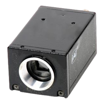
Rear protrusion on the C-mount lens must be less than 10mm (0.4 inches approx.). When IR-cut filter is used, it must be less than 7.0 mm (0.28 inches approx.). The IR-cut filter is placed in the C-mount thread. The C-mount IR-cut filter must be ordered separately. CV-M30 Fig. 1. Locations - 3 -... -
Page 5: Pin Assignment
Type: HR10A-10R-12PB-01 (Hirose) male Seen from rear. Fig. 2. 12 pin connector 5.2. 6-pin Multi-connector (TRIGGER) Type: HR10A-7R-6PB (Hirose) male Seen from rear. Fig. 3. 6 pin connector CV-M30 Pin no Signal +12 V DC input Video output HD input VD/trig input... -
Page 6: Input And Output Diagram
CV-M30 5.3. Input and Output Diagram Fig. 4. WEN and EEN output Fig. 5. HD and VD/Trigger input - 5 -... -
Page 7: Functions And Operations
PULSE WIDTH The trigger input is AC coupled, and the exposure will start at the first HD pulse after the trigger falling edge. The trigger pulse width should be > 1H to < 1000H. CV-M30 Trigger Exposure shutter time Trigger Exposure Fig. -
Page 8: Edge Pre-Select Mode
The edge pre-select mode will work in non-interlaced and field accumulation mode with partial scanning and double speed. The CV-M30 starts the exposure (= accumulation of photoelectric charge) at the first HD pulse after the falling edge of the ext. trigger pulse. The exposure ends after the time set by the 3 shutter switches SW1-1 to SW1-3. -
Page 9: Pulse Width Control Mode
The pulse width control mode will only work in non-interlaced field accumulation mode. The exposure is controlled by the low period of the ext. trigger pulse. The CV-M30 starts the exposure at the first HD pulse after the falling edge of the ext. trigger pulse. The exposure ends at the first HD pulse after the rising edge of the ext. -
Page 10: Other Functions
6.4. Other Functions 6.4.1. Double Speed Mode The CV-M30 camera revision D operates only with double speed scanning. Double speed is 120 fields per second. (V= 119.88Hz. H=31.468 kHz). To use this mode. Set: 6.4.2. Partial Scanning Mode To obtain a higher frame rate, the partial scanning can be used. In this mode only the vertical center part of the CCD sensor is read out. -
Page 11: External Sync Mode
CV-M30 6.5.2. External Sync Mode H = 31.778 µs Fig. 10. Vertical timing with external sync 6.5.3. External Sync Mode. Partial Scan H = 31.778 µs H = 31.778 µs Fig. 11. Partial scanning vertical timing with external sync - 10 -... -
Page 12: Edge Pre-Select
Fig. 12. Vertical timing for Edge pre-select 6.5.5. Edge Pre-select. Partial Scan Fig. 13. Vertical timing for Edge pre-select 1/2 partial scanning Fig. 14. Vertical timing for Edge pre-select 1/3 partial scanning CV-M30 - 11 - H = 31.778 µs H = 31.778 µs... -
Page 13: Pulse Width Control
CV-M30 6.5.6. Pulse Width Control H = 31.778 µs Fig. 15. Vertical timing for pulse width control 6.5.7. Pulse Width. Partial Scan H = 31.778 µs Fig. 16. Vertical timing for pulse width control 1/2 partial scanning H = 31.778 µs Fig. -
Page 14: Table For Shutter Time
SW1-1, SW1-2 and SW1-3 is for shutter speed setting. For 1/2 partial scan thel double speed range is 1/250 to 1/20,000. For 1/3 partial scan the range is from 1/500 to 1/20,000. SW1-1 SW1-2 SW1-3 CV-M30 OFF = < ON = > SW 1 < <... -
Page 15: Scan Mode Settings
Off: is manual gain, which can be adjusted by the potentiometer on the rear panel. On: is AGC mode. The AGC video level can be adjusted by an internal potentiometer VR1 on PK8210B board. Please refer to “8. Internal Adjustments of Video Signal.” CV-M30 Remarks In Normal trigger mode only. (Continuous). Non-interlaced only... -
Page 16: Internal Switch And Jumper Settings
On the PK8210 board there are 2 jumpers for gamma select. The jumper is mounted as a 1KΩ resistor. Gamma JP31 JP36 1KΩ 0.45 1KΩ 7.2.4. Internal Switch Positions 7.2.5. Internal Jumper Positions CV-M30 Remarks Factory setting Fig. 19. Internal switch positions Fig. 20. Internal jumper positions - 15 -... -
Page 17: Internal Adjustments Of Video Signal
CV-M30 8. Internal Adjustments of Video Signal For adjustment of the video output signal there are internal potentiometers on th PK 7987A board. Adjustment should only be done in a setup with a standard test chart and controlled illumination Do not touch these potentiometers unless you are familiar with camera adjustments. -
Page 18: External Appearance And Dimensions
CV-M30 9. External Appearance and Dimensions Fig. 22. Outline - 17 -... -
Page 19: Specifications
Power Consumption Dimensions Weight Note: Above specifications are subject to change without notice. 10.2. Spectral Sensitivity CV-M30 CV-M30 1/2”Monochrome IT CCD. Sony ICX-418ALL-6 6.45mm (H) x 4.84mm (V) 768(H) x 494(V) 8.4 µ m(H) x 9.8 µm(V) 756(h) x 485(v) 60 frames/sec... -
Page 20: Appendix
CV-M30 11. Appendix 11.1. Precautions Personnel not trained in dealing with similar electronic devices should not service this camera. The camera contains components sensitive to electrostatic discharge. The handling of these devices should follow the requirements of electrostatic sensitive components. -
Page 21: Users Record
Company and product names mentioned in this manual are trademarks or registered trademarks of their respective owners. JAI A-S cannot be held responsible for any technical or typographical errors and reserves the right to make changes to products and documentation without prior notification.
Need help?
Do you have a question about the CV-M30 and is the answer not in the manual?
Questions and answers