Table of Contents
Advertisement
Quick Links
AN2018-01 EVAL-M1-101T User Manual
EVAL-M1-101T User Manual
iMOTION™ Modular Application Design Kit
About this document
Scope and purpose
This application note provides an overview of the evaluation board EVAL-M1-101T including its main features,
key data, pin assignments and mechanical dimensions.
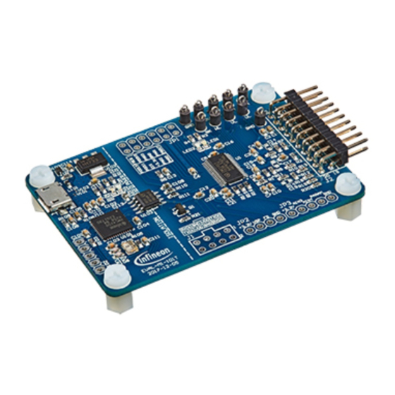
EVAL-M1-101T is an evaluation-board as part of the iMOTION™ Modular Application Design Kit. This board
features and demonstrates Infineon's Advanced Motion Control Engine (MCE 2.0) technology for permanent
magnet motors drive over the full speed range.
The evaluation board EVAL-M1-101T was developed to support customers during their first steps designing
applications with running any permanent magnet motor via sensorless sinusoidal control.
Intended audience
This application note is intended for all technical specialists who know motor control and high power
electronics converter and this board is intended to be used under laboratory conditions.
Table of contents
About this document ....................................................................................................................... 1
Table of contents ............................................................................................................................ 1
1
Safety precautions ................................................................................................................. 3
2
Introduction .......................................................................................................................... 4
3
EVAL-M1-101T main features ................................................................................................... 5
3.1
Functional description ............................................................................................................................ 6
3.2
IMC101T-T038 pinout description .......................................................................................................... 6
3.3
EVAL-M1-101T board specifications ....................................................................................................... 8
3.4
Pin assignment ........................................................................................................................................ 9
4
Getting Started with EVAL-M1-101T......................................................................................... 11
4.1
Setting up the system............................................................................................................................ 11
4.2
iMOTION™ development tools and software ....................................................................................... 13
4.2.1
MCEWizard setup overview .............................................................................................................. 13
4.2.2
MCEDesigner setup overview .......................................................................................................... 15
5
Hardware description of EVAL-M1-101T ................................................................................... 18
5.1
Current feedback circuitry .................................................................................................................... 18
5.1.1
Shunt configuration ......................................................................................................................... 18
5.1.2
External Current feedback configuration and calculation ............................................................. 18
5.1.3
Internal Current feedback amplifier gain configuration ................................................................ 20
5.2
EVAL-M1-101T analog inputs and their MCEWizard setup ................................................................... 21
5.2.1
DC bus sensing configuration .......................................................................................................... 21
5.2.2
NTC shutdown value calculation and configuration ...................................................................... 22
5.2.3
VSP analog input control mode and PGout configuration ............................................................. 23
5.3
Schematics overview ............................................................................................................................ 26
5.4
PCB layout overview ............................................................................................................................. 27
User Manual
Please read the Important Notice and Warnings at the end of this document
Revision 1.6
2018-11-27
Advertisement
Table of Contents

Related Manuals for Infineon iMOTION EVAL-M1-101T


Summary of Contents for Infineon iMOTION EVAL-M1-101T
-
Page 1: Table Of Contents
EVAL-M1-101T is an evaluation-board as part of the iMOTION™ Modular Application Design Kit. This board features and demonstrates Infineon’s Advanced Motion Control Engine (MCE 2.0) technology for permanent magnet motors drive over the full speed range. - Page 2 EVAL-M1-101T User Manual iMOTION™ Modular Application Design Kit Table of contents Bill of material ........................29 Reference ..........................31 Revision history..........................32 User Manual 2 of 33 Revision 1.6 2018-11-27...
-
Page 3: Safety Precautions
EVAL-M1-101T User Manual iMOTION™ Modular Application Design Kit Safety precautions Safety precautions In addition to the precautions listed throughout this manual, please read and understand the following statements regarding hazards associated with development systems. Table 1 Precautions Attention: The ground potential of the EVAL-M1-101T system is biased to a negative DC bus voltage potential. -
Page 4: Introduction
USB connector and on board debugger isolated by digital isolator, and UART interface. The EVAL-M1-101T evaluation board is available from Infineon. The features of this board are described in the main features chapter of this document, whereas the remaining paragraphs provide information to enable the customers to copy, modify and qualify the design for production according to their own specific requirements. -
Page 5: Eval-M1-101T Main Features
Modular Application Design Kit EVAL-M1-101T main features EVAL-M1-101T main features EVAL-M1-101T is an evaluation control board for motor control applications. The kit demonstrates Infineon’s motion control IC technology. Main features of the IMC101T-T038 Motion Control IC are: MCE (Motion Control Engine) as ready-to-use solution for variable speed drives ... -
Page 6: Functional Description
EVAL-M1-101T User Manual iMOTION™ Modular Application Design Kit EVAL-M1-101T main features Functional description Figure 2 shows a typical motor control application block diagram using the IMC101T-T038. The IMC101T-T038 provides a built-in closed loop sensorless control algorithm using the unique flexible Motion Control Engine (MCE) for permanent magnet motors. - Page 7 EVAL-M1-101T User Manual iMOTION™ Modular Application Design Kit EVAL-M1-101T main features Table 2 lists the available pins of IMC101T-T038 with short descriptions. For more detailed information, please refer to the datasheet or User Manual for iMOTION™ IMC101T-T038 motor control IC. Table 2 IMC101T-T038 pinout description Pin#...
-
Page 8: Eval-M1-101T Board Specifications
EVAL-M1-101T User Manual iMOTION™ Modular Application Design Kit EVAL-M1-101T main features REFW Itrip phase W reference Phase W current leg sensing not used EVAL-M1-101T board specifications Table 3 depicts the important specifications of the evaluation board EVAL-M1-101T. Table 3 EVAL-M1-101T board specifications Parameters Values Conditions / comments... -
Page 9: Pin Assignment
EVAL-M1-101T User Manual iMOTION™ Modular Application Design Kit EVAL-M1-101T main features Parameters Values Conditions / comments System environment Ambient temperature -40 - 105° C Pin assignment Essential information about the connections of the EVAL-M1-101T evaluation board is described below. Table 4 includes the details of UART connectors. Table 4 J1- UART Connector Pin Nr. - Page 10 EVAL-M1-101T User Manual iMOTION™ Modular Application Design Kit EVAL-M1-101T main features Name Pin Name Connectors Thermistor input Shunt voltage phase V Ground Shunt voltage phase W Ground Defined for 15 V Power Supply (not used in this board) Table 6, Table 7 and Table 8 include the details of test signal pin connectors. Table 6 Digital signal test pin connecter JP1 Name...
-
Page 11: Getting Started With Eval-M1-101T
Refer to chapters 0 and 4.2.2 as well as MCEWizard and MCEDesigner documentation for more information. 1. Get the latest ”IMC101T-T038 MCE Software Package” available on www.infineon.com/imotion-software web page. 2. Connect PC-USB connector on the on-board-debugger to the PC via USB cable. - Page 12 EVAL-M1-101T User Manual iMOTION™ Modular Application Design Kit Getting Started with EVAL-M1-101T 7. Start MCEDesigner tool and open MCEDesigner default configuration file (.irc) for IMC101T-T038 controller (IMC101T_Vxxx.irc) by clicking “File” > “Open”. IMC101T_Vxxx.irc file is included in the ”IMC101T-T038 MCE Software Package”...
-
Page 13: Imotion™ Development Tools And Software
“Welcome Page” for MCEWizard, where the MADK control board or power board can be selected through the pull-down list. Infineon keeps releasing new MADK controller and power boards. Therefore, it could happen that some of the newest power boards are not pre-configured in the MCEWizard tool and cannot be selected through the pull-down menu. - Page 14 EVAL-M1-101T User Manual iMOTION™ Modular Application Design Kit Getting Started with EVAL-M1-101T iMOTION™ MADK system enables users to easily test different combination of control and power board with their motors. User should be familiar with the system level parameters which are related to the motor used. There is a very limited number of parameters which are specific to the control board or power board hardware.
-
Page 15: Mcedesigner Setup Overview
EVAL-M1-101T User Manual iMOTION™ Modular Application Design Kit Getting Started with EVAL-M1-101T 4.2.2 MCEDesigner setup overview After installing MCEDesigner installer, there is a shortcut for MCEDesigner on Windows desktop. Double click the shortcut to open MCEDesigner and then open “IMC101T_xx.irc” file as shown in Figure 8. Figure 8 MCEDesigner’s Main Display for EVAL-M1-101T MCEDesigner programmer function can be used to program IMC101T-T038 firmware and/or System... - Page 16 EVAL-M1-101T User Manual iMOTION™ Modular Application Design Kit Getting Started with EVAL-M1-101T Figure 9 Program Firmware and Parameter in “Program IMC Controller” pop-up window To program only Drive System Parameter file into IMC101T-T038, click on “Tools” menu and select “Programmer” in the pull down list. The pop-up window “Program IMC controller” will show up as in Figure 10. Click on the “Program Parameters”...
- Page 17 3.3V access/test points if the power board is not attached to the EVAL-M1-101T control board. All latest firmware file for different type of iMOTION control ICs are available for download via Infineon iMOTION website (http://www.infineon.com/imotion-software).
-
Page 18: Hardware Description Of Eval-M1-101T
EVAL-M1-101T User Manual iMOTION™ Modular Application Design Kit Hardware description of EVAL-M1-101T Hardware description of EVAL-M1-101T This chapter covers hardware design of the EVAL-M1-101T in more details. To enable users to make the EVAL- M1-101T evaluation board a basis for a new development or modification of their own systems, all necessary technical data like schematics, layout and components are also included in this chapter. - Page 19 EVAL-M1-101T User Manual iMOTION™ Modular Application Design Kit Hardware description of EVAL-M1-101T Figure 13 depicts IU+ current feedback sensing circuity on EVAL-M1-101T evaluation board. Please note that the default external amplification gain is less than 1 for current sense in this evaluation board. +3.3V iMOTION 10k, 1%...
-
Page 20: Internal Current Feedback Amplifier Gain Configuration
EVAL-M1-101T User Manual iMOTION™ Modular Application Design Kit Hardware description of EVAL-M1-101T 5.1.3 Internal Current feedback amplifier gain configuration The iMOTION™ controller on this board has the internal current feedback programmable gain amplifier which has four gain settings: 1x, 3x, 6x and 12x. The internal Current feedback amplifier gain can be configured in MCEWizard as shown in Figure 15. -
Page 21: Eval-M1-101T Analog Inputs And Their Mcewizard Setup
EVAL-M1-101T User Manual iMOTION™ Modular Application Design Kit Hardware description of EVAL-M1-101T EVAL-M1-101T analog inputs and their MCEWizard setup Besides current sensing inputs, IMC101T-T038 provides number of analog inputs for different system functions. Figure 16 depicts analog inputs of the IMC101T-T038 except current sensing inputs. AIN3 AIN3 AIN4... -
Page 22: Ntc Shutdown Value Calculation And Configuration
EVAL-M1-101T User Manual iMOTION™ Modular Application Design Kit Hardware description of EVAL-M1-101T 5.2.2 NTC shutdown value calculation and configuration External NTC Temperature shutdown value can be calculated as shown below and configured in MCEWizard as shown in Figure 18. For pull-up resistor on evaluation power board and NTC value, please refer to the power board’s Application Note. -
Page 23: Vsp Analog Input Control Mode And Pgout Configuration
EVAL-M1-101T User Manual iMOTION™ Modular Application Design Kit Hardware description of EVAL-M1-101T 5.2.3 VSP analog input control mode and PGout configuration VSP analog input control mode can be configured in the options page for MCEWizard by clicking and selecting in the pull down list marked with red box as shown in Figure 19. Figure 19 Analog VSP control input mode configuration There are three input thresholds (percentage of controller supply voltage VDD) used to define the relationship... - Page 24 EVAL-M1-101T User Manual iMOTION™ Modular Application Design Kit Hardware description of EVAL-M1-101T After configured the Analog VSP control input mode, the three input thresholds can be set up in the input text box in MCEWizard marked with red box as shown in Figure 21, or in the pages for Question 9, Question10 and Question 11.
- Page 25 EVAL-M1-101T User Manual iMOTION™ Modular Application Design Kit Hardware description of EVAL-M1-101T Motor speed can be calculated as shown below. ���������� ������������������ ( ���� ) ∗ ������ ���������� ���������� ( ������ ) = ���������� ������ �������������������� For example, PGOUT frequency is about 80 Hz and Pulse per Revolution is 6, and then the motor speed will be 800 RPM.
-
Page 26: Schematics Overview
EVAL-M1-101T User Manual iMOTION™ Modular Application Design Kit Hardware description of EVAL-M1-101T Schematics overview Figure 24 shows the schematic of EVAL-M1-101T evaluation board with IMC101T-T038 controller. +3.3V +3.3V +3.3V +3.3V 10uF, 10V PWMUH PWMUH AIN3 RXD0 PWMUL AIN3 RXD0 PWMUL TXD0 +3.3V TXD0... -
Page 27: Pcb Layout Overview
35µm copper by default and its size is 65 mm × 45 mm. The PCB board thickness is 1.6mm. Check the Infineon’s website or get in contact with Infineon’s technical support team to get more detailed information and the latest Gerber-files. - Page 28 EVAL-M1-101T User Manual iMOTION™ Modular Application Design Kit Hardware description of EVAL-M1-101T The top layer routing of the PCB is provided in the following Figure 28. Figure 28 Top layer routing of the EVAL-M1-101T Figure 29 illustrates the bottom layer routing of the PCB. Figure 29 Bottom layer routing of the EVAL-M1-101T User Manual...
-
Page 29: Bill Of Material
Wurth Electronics Inc. LED BLUE CLEAR 0603 SMD LED102 150060BS75000 Wurth Electronics Inc. LED GREEN CLEAR 0603 SMD LED2, 150060GS75000 Wurth Electronics Inc. LED101 MOSFET N-CH 30V 2.7A SOT-23-3 IRLML2030 Infineon Technologies User Manual 29 of 33 Revision 1.6 2018-11-27... - Page 30 BLACK TP3/UL, TP4/VH, TP5/VL, TP6/WH, TP7/WL, TP8/GND, TP9/GK, TP10/GND IC MCU 32BIT 128KB FLASH IMC101T-T038 Infineon Technologies 38TSSOP IC MCU 32BIT 256KB FLASH U101 XMC4200-Q48F256 Infineon Technologies 48VQFN IC REG LINEAR 3.3V 1A SOT223-4 U102 IFX1117-ME V33 Infineon Technologies DGTL ISO 3.75KV GEN PURP 8SOIC...
-
Page 31: Reference
IMC100 Series Datasheet iMOTION™ IMC100 Software Reference Manual MCEWizard User Guide MCEDesigner User Guide Note: All listed reference materials are available for download on Infineon’s website www.infineon.com/imotion. All the iMOTION™ MADK power board’s Application Notes are available at www.infineon.com/MADK... -
Page 32: Revision History
EVAL-M1-101T User Manual iMOTION™ Modular Application Design Kit Reference Revision history Document Date of release Description of changes version 2018-01-31 First release 2018-01-31 Moved to latest template plus small modifications 2018-02-09 plus small modifications 2018-03-02 plus small modifications 2018-03-29 plus small modifications 2018-11-27 Modified MCEDesigner setup description in section 4.2.2. -
Page 33: Www.infineon.com
Infineon Technologies hereby disclaims dangerous substances. For information on the types © 2018 Infineon Technologies AG. any and all warranties and liabilities of any kind in question please contact your nearest Infineon All Rights Reserved. (including without limitation warranties of non- Technologies office.
Need help?
Do you have a question about the iMOTION EVAL-M1-101T and is the answer not in the manual?
Questions and answers