
Related Manuals for Stryker Medical Trauma 1020


Summary of Contents for Stryker Medical Trauma 1020
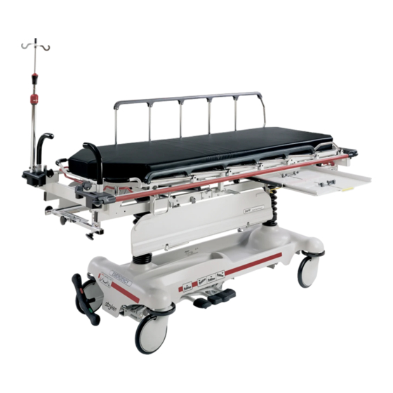
- Page 1 Trauma Series 1020 Full–Length X–Ray Stretcher Operations Manual For Parts or Technical Assistance 800–327–0770...
-
Page 2: Table Of Contents
Table of Contents Introduction ................2, 3 Operating Base Controls . -
Page 3: Introduction
Introduction INTRODUCTION This manual is designed to assist you with the operation of the 1020 Full–Length X–Ray Emergency Room Stretcher. Read it thoroughly before using the equipment or beginning any maintenance on it. SPECIFICATIONS Maximum Weight Capacity 400 pounds Overall Bed Length/Width 86.5”/31.25”... - Page 4 Introduction Before operating this stretcher, it is important to read and understand all information in this manual. Carefully read and strictly follow the warnings listed on this page. WARNING Be sure to move any equipment that may be in the way before raising or lowering the litter height. Always apply the caster brakes when a patient is getting on or off the stretcher.
-
Page 5: Operating Base Controls
Stretcher Operation OPERATING BASE CONTROLS – SIDE CONTROL WITH UNI–LOWER PEDAL Pump to raise litter. Depress in the center of pedal (B) to lower both ends of the stretcher together. Depress the side of pedal (B) closest to the foot end of the stretcher to lower the foot end. Depress the side of pedal (B) closest to the head end of the stretcher to lower the head end. - Page 6 Stretcher Operation OPERATING BASE CONTROLS – SIDE CONTROL WITH DUAL LOWERING PEDALS Pump to raise litter. Depress to lower head end. Depress to lower foot end. Note: Depress B & C together to lower both ends of the litter simultaneously. Brake and Steer functions (foot end).
- Page 7 Stretcher Operation OPERATING BASE CONTROLS – END CONTROL Pump to raise litter. Depress to lower head end. Depress to lower foot end. Note: Depress B & C together to lower both ends of the litter simultaneously. Brake and Steer functions (foot end) Brake and Steer functions (head end)
-
Page 8: Raising And Lowering Litter Height
Stretcher Operation RAISING AND LOWERING LITTER HEIGHT – SIDE CONTROL/UNI–LOWER PEDAL CAUTION Be sure to move any equipment that may be in the way before raising or lowering the litter height. To raise the litter height, pump pedal (A) repeatedly until the desired height is achieved (see illustration on page 4). - Page 9 Stretcher Operation TRENDELENBURG/REVERSE TRENDELENBURG – SIDE CONTROL/UNI–LOWER PEDAL NOTE Litter height must be raised first in order to achieve a trend. or reverse trend. position. CAUTION Be sure to remove any equipment that may be in the way before lowering stretcher. For Trendelenburg positioning (head down), depress the side of pedal (B) closest to the head end of the stretcher (see illustration, page 4).
-
Page 10: Applying The Brake System
Stretcher Operation APPLYING THE BRAKE SYSTEM NOTE For user convenience, the brake/steer pedal is located on both ends of the stretcher. WARNING Always apply the caster brakes when a patient is getting on or off the stretcher. Push on the stretcher to en- sure the brakes are securely locked. - Page 11 Stretcher Operation OPERATING THE BIG WHEEL OPTION When the brake/steer pedal is in the neutral or brake position, the Big Wheel is elevated approxi- mately 1” and the stretcher rests on the four casters. NOTE The two Big Wheels do not pivot. The stretcher cannot be moved directly sideways with the Big Wheel activated.
- Page 12 Notes...
-
Page 13: Using Siderails
Stretcher Operation USING SIDERAILS CAUTION Be sure the siderail latching mechanism (B) is working properly at all times. If it is not, refer to your stretcher maintenance manual for ”Siderail Latch Adjustment”. To engage siderails: Pull up siderail (A) and raise to full up position so that latch (B) engages. (See illustra- tion). -
Page 14: Using The Safrt Patient Transfer Board/Arm Board
Stretcher Operation USING THE SAFRt PATIENT TRANSFER BOARD WARNING When using the SAFRt Board to transfer a patient, always lock the brakes on all stretchers, beds, etc. being used and always be certain the transfer board is placed securely on the surface of the mating stretcher or bed. -
Page 15: Operating The Fowler
Stretcher Operation USING THE SAFR PATIENT TRANSFER BOARD/ARM BOARD (CONTINUED) Using the SAFR Board as an armboard: 1. Raise the support post (D) to the up position. 2. Raise the transfer board (C) from the bottom while lifting from the top. 3. - Page 16 Stretcher Operation OPERATING OPTIONAL 2–STAGE PERMANENTLY ATTACHED I.V. POLE DETAIL OF I.V. POLE LATCH NOTE The 2–stage permanently attached I.V. pole is an option and may have been installed at either the head, foot or both ends of the stretcher. The choice was made at the time the stretcher was purchased. To use the 2–stage permanently attached I.V.
- Page 17 Stretcher Operation OPERATING OPTIONAL 3–STAGE PERMANENTLY ATTACHED I.V. POLE DETAIL OF I.V. POLE LATCH DETAIL OF I.V. POLE GRIP NOTE The 3–stage permanently attached I.V. pole is an option and may have been installed at either the head, foot or both ends of the stretcher. The choice was made at the time the stretcher was purchased. To use the 3–stage permanently attached I.V.
-
Page 18: Operating Optional Tethered I.v. Pole
Stretcher Operation OPERATING OPTIONAL TETHERED I.V. POLE To use the tethered I.V. pole: 1. Remove the I.V. pole from the storage trough under the litter and insert into the receptacle on the corner of the litter frame. 2. To raise the height of the pole, turn knob (A) count- erclockwise and pull up on the telescoping portion (B) of the pole to raise it to the desired height. -
Page 19: Using The Optional Fowler X-Ray Cassette Holder
Stretcher Operation OPERATING THE OPTIONAL FOOT EXTENSION/DEFIBRILLATOR TRAY 1. To use as a defibrillator tray, pull out the top knob (A) and pivot the tray (B) over the foot extension (C) until the tray extends flat over the foot end of the stretcher. 2. -
Page 20: Using The Full Length X-Ray Cassette System
Stretcher Operation USING THE FULL LENGTH X–RAY CASSETTE SYSTEM NOTE Before beginning the following procedure, center the patient on the stretcher by using the position indicator labels located on both ends of the stretcher (see illustration above). 1. The cassette drawer is located on the side of the stretcher and can be identified by the yellow handle (B). Using handle (B), pull drawer fully out. -
Page 21: Preventative Maintenance Checklist
Preventative maintenance should be performed at a minimum of annually. A preventative maintenance pro- gram should be established for all Stryker Medical equipment. Preventative maintenance may need to be performed more frequently based on the usage level of the product. -
Page 22: Cleaning
Cleaning Hand wash all surfaces of the stretcher with warm water and mild detergent. Dry thoroughly. DO NOT STEAM CLEAN, PRESSURE WASH, HOSE OFF OR ULTRASONICALLY CLEAN. Using these methods of cleaning is not recommended and may void this product’s warranty. Clean Velcro AFTER EACH USE. -
Page 23: Warranty
No employee or representative of Stryker is authorized to change this warranty in any way. Stryker Medical stretchers are designed for a 10 year expected life under normal use conditions and appropri- ate periodic maintenance as described in the maintenance manual for each device. -
Page 24: Return Authorization
Claims for any short shipment must be made within thirty (30) days of invoice. International Warranty Clause: This warranty reflects U.S. domestic policy. Warranty outside the U.S. may vary by country. Please contact your local Stryker Medical representative for additional information. - Page 25 European Representative Stryker EMEA RA/QA Director Stryker France ZAC Satolas Green Pusignan Av. De Satolas Green 69881 MEYZIEU Cedex France 6300 S. Sprinkle Road, Kalamazoo, MI 49001-9799 (800) 327-0770 www.strykermedical.com DH 7/03 1020-032-138 REV F...
Need help?
Do you have a question about the Trauma 1020 and is the answer not in the manual?
Questions and answers