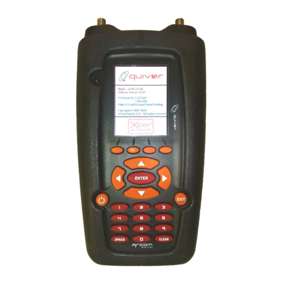

Summary of Contents for Arcom Digital Quiver XT
- Page 1 Quiver XT User Guide Quiver XT and XT-UB v.1.3.1 Firmware release XT4.19 and above Q-browser release 5.0.0.11 and above 12/04/18 This document describes the operation and feature set of the Quiver XT.
-
Page 2: Table Of Contents
Return band ..........................11 FWD scan list ..........................11 Sweep profile ..........................12 Settings - Calibration ........................12 Quiver XT Operation Modes ....................... 13 CPD Radar Mode ........................13 Passive CPD Radar ......................... 14 CPD Radar Connection Diagrams ....................15 Amplifier Connection ........................ - Page 3 Spectrum analyzer/Signal level meter modes ................35 Return spectrum analyzer mode ....................35 LNA – low noise amplifier ......................37 Reference level change ......................... 37 Scale change ..........................38 Markers ............................39 Using Max Hold ..........................40 Hold feature ..........................41 Saving a Spectrum Analyzer Trace ....................
-
Page 4: Introduction
FFT spectrum analyzer, QAM demodulator, Simple Return Sweep and leakage detector. Two version of Quiver XT are available, a standard version which works with the Hunter system, and an unbundled version for stand-alone operation. The standard version when used with Hunter provides a method of node calibration... -
Page 5: Navigation Buttons
Navigation Buttons Power ON/OFF: To turn the unit on, press for 3 second; to turn the unit off, press and hold for 3 seconds and select Power down option. Select Standby for putting the meter into power saving state with fast launch. -
Page 6: Inputs And Outputs
Inputs and Outputs F-Ports: The F-Type RF ports change purpose based on the menu selection and are identified on the LCD display. For example, when in CPD mode the port functions as Forward and Return Inputs, while in TDR mode the port functions are Tx and Rx. Forward/Tx/Antenna: Connects to the forward test port at the amplifier or fiber node, or to one of the outputs of the QTP-20 Test Probe (used at any device that does... -
Page 7: Startup
Startup To turn on the Quiver, push the Power ON/OFF button and hold for 3 seconds. Once the unit is on, you will see the following screen, landing on the Operation modes page. Brightness and Audio control Brightness and volume control is accesses by pressing the Brightness / Volume hot key accessed from the main menu page. -
Page 8: Settings
Press the settings hotkey to access various items. Settings - General The General setting button contains information on the FSK data carrier and frequency for use with the complete Hunter system (not relevant with unbundled versions of Quiver XT), as well as background color changes. -
Page 9: Setting Up The Fsk Data Carrier Band And Fsk Frequency
Setting Up the FSK Data Carrier Band and FSK frequency This section is only applicable for the standard version of the Quiver XT and can be disregarded when using the Unbundled version Quiver uses an FSK carrier to communicate with headend equipment. Prior to operating the system, you must set the frequency of the data carrier. -
Page 10: Background
Background Allows to change from a white to black background color. Settings – Measurement Setting operation standards In order to operate properly in the forward spectrum analyzer and analog leak detector modes this is necessary to set properly the TV standard that is used by the cable plant. -
Page 11: Distance Scale
Distance scale Select feet vs. meter – this setting is generic across multiple operational modes. Return band This configures the return bandwidth of the used, used across multiple modes of operation. FWD scan list This feature is used to select channels to display in the SLM, if the user wants to view certain channels instead of all channels. -
Page 12: Sweep Profile
Sweep profile Sweep profile allows the operator to review the output frequencies of the stored profiles. Up to 64 frequency points can be viewed for each profile. Use the left and right arrow key to select a sweep profile. Settings - Calibration Calibration is used to change various parameters at the factory, it is not a setting that a user should ever require access to. -
Page 13: Quiver Xt Operation Modes
Quiver XT Operation Modes Quiver XT has 8 main operating modes. CPD radar modes consist of active and passive radars and are used to precisely range distance to CPD or any nonlinear distortion. NTC TDR mode contains a network traffic... -
Page 14: Passive Cpd Radar
CPD using in the complete 5-100 MHz Return Band. While using CPD radar with a Quiver XT you have the option to operate in either local or headend mode. In local mode the distance to the CPD source is displayed as described above. -
Page 15: Cpd Radar Connection Diagrams
CPD Radar Connection Diagrams To use CPD Radar Mode, you must establish proper connection to the network devices. The diagrams illustrate the proper CPD/leg Isolation setups to use for the various devices in the network. Node Connection Node Connection – Single Output Amp/Fiber Node... - Page 16 Node Connection – Isolation at Fiber Node...
-
Page 17: Amplifier Connection
Amplifier Connection Node Connection – Isolation at Amplifier... -
Page 18: Tap And Splitter Connection
Tap and Splitter Connection Tap and Splitter Connection – Isolation at Tap/Splitter... -
Page 19: End Of Line Cpd
End of Line CPD When you get to the last tap at the end of line and suspect that the CPD is coming from a house, you will have to use the Quiver in Headend View. Connect the Quiver Forward Port to the tap and keep disconnecting the houses (tap ports 1- 8) one by one while watching the Quiver screen in headend view. -
Page 20: Using Cpd Radar In Local View
Using CPD Radar in Local View When you activate CPD Radar Mode from the Operation Modes (by hitting key 1 or highlighting with the cursor buttons and pressing <ENTER>), the default is Local view. The following screen will appear: The Quiver is constantly scanning for CPD sources, and you will see slight changes on the screen as the scanning occurs. -
Page 21: Selecting Cpd Detection Filter Bandwidth
peak which remains constant. The benefit is that in smaller time delay window the scan is completed much faster than in the full-time delay span saving time in the field. Selecting CPD detection filter bandwidth The return signal input filter bandwidth can be changed to reduce the influence of CW like carriers in the return path on the radar signal processing circuitry. - Page 22 Noise compression settings screen – <Enter>ing High suppression mode Please note that now a single scan through the full range of time delay for CPD signals may take long – up to 180 seconds. The expanding horizontal blue bar at the top of the screen is indicating the scan progress.
-
Page 23: Using The Cpd Marker Option
Using the CPD Marker Option Quiver automatically sets a marker at the maximum level in the CPD signal response. To move marker to a next or previous peak, use the ∨ to highlight menu item Marker or hit 5 on keypad and press <Enter> to open the dialog box then use the ^ and v cursor keys select ‘<>’... -
Page 24: Zoom Mode In Passive Radar
Zoom mode in Passive radar In this mode the CPD correlator works with the full return bandwidth, 5-42/65/85 to provide better time/distance resolution. The return bandwidth of the cross correlator is selected at Settings – Measurement. Press the Zoom button to access from the Passive radar screen. -
Page 25: Filtering Of Analog Channels - Important
XT contains an internal high pass filter that removes all analog channels above a specified frequency. If Quiver XT is used on a network with analog channels carried above the cutoff of the internal filter, an external high pass filter must be used. This external filter should be placed on the FWD in port when using the Passive CPD radar mode. -
Page 26: Ntc Tdr
Active Radar warning message NTC TDR The NTC TDR identifies the precise distance to micro-reflection problems and impedance mismatches in the plant. It is used as a field tool to locate problems identified from PNM initiatives. The NTC TDR is completely different from any other existing TDR. - Page 27 WHEN USING THE NTC TDR CONNECTED TO AN AMPLIFIER, PLEASE BE VERY CAREFUL IN SELECTING THE PROPER TEST PORT AS THEY ARE DIFFERENT THAT WHAT IS TYPICALLY USED – THE INPUT NEEDS TO BE RETURN INPUT IN THE FORWARD, AND OUTPUT NEEDS TO BE RETURN OUT IN THE RETURN! The NTC TDR output display is unique in that it provides a presentation of easily understandable return loss across the measured span.
- Page 28 20dB 2 port test probe connected directly to the center conductor via the seizure screw access port as shown below. Quiver S shown instead of Quiver XT The spread spectrum probing signal transmit signal can be set from -10 .. +10dBmV, the recommended and default level is 0dBmV.
-
Page 29: Connecting To A Line Passive
The Arcom Digital Q-AMP is designed for this purpose. Since we need to amplify the very low level Received (Rx) signal, the Q-AMP must be placed on the Rx... -
Page 30: Connecting To An Amplifier
Connecting to an amplifier When connecting to an amplifier, great care and attention needs to be given to ensure the proper test ports are utilized and connected to the proper transmit and receive ports. The required configuration is illustrated below – where the 5-42MHz transmitted signal is inserted in the forward direction via a return input test port such that it can pass through the diplex filter, and the reflected signal is received by a return out test port... -
Page 31: Connecting To A Length Of Cable
Connecting to a length of cable When using the NTC TDR on a single length of cable, in order to display proper results, it is recommended to use a two-way splitter with the outputs connected to the transmit and receive ports of the TDR, and with a 20dB pad installed between the splitter input and the length of cable as shown in the diagram below. -
Page 32: Using The Tdr
Using the TDR Due to differences in signal level when connecting to an amplifier test point versus the QTP test probe when connecting to a passive, when entering NTC TDR mode the user must first select the connection method of Probe or Amplifier, then check settings to confirm VOP and Cable type, then press the Run hot key to start TDR functionality. -
Page 33: Tdr Settings - Vop
TDR Settings – VOP The velocity of propagation number should correspond to the type of cable being testing according to manufacturers’ specification. It is used for both the NTC TDR and the CPD radar. A typical value is .87 %. Quiver uses calculated time distance from the time the pulse is sent to the time it is received –... -
Page 34: Recommended Tdr Signal Level
Recommended TDR signal level The default transmit level for the TDR is 0 dBmV. Under typical conditions this will result in the spread spectrum signal being -40dBc relative to the return QAM channels – significantly lower than the -25dBc level defined in the DOCSIS specification as what is required not to affect the return QAM CNR/SNR. -
Page 35: Spectrum Analyzer/Signal Level Meter Modes
Spectrum analyzer/Signal level meter modes Return spectrum analyzer mode Bandwidth of the return spectrum analyzer is 100 MHz. Enter RTN mode and connect return input to the indicated port. To set up Start frequency, highlight the settings menu item <Min frequency> by using the cursor keys or hit 1 on the numerical keypad and press <Enter>. - Page 36 Select Min Frequency Should you make an error typing in the frequency, use Clear all soft key to clear the field and type the frequency again. To set up Stop frequency highlight the settings menu item <Max frequency> by using the cursor keys or hit 2 on the numerical keypad and press <Enter>. Then in the appearing dialog box type in required frequency using the numerical keypad and press OK soft key.
-
Page 37: Lna - Low Noise Amplifier
Select Max Frequency LNA – low noise amplifier The analyzer has 20dB LNA that can be turned on when watching very low signals. Note: this is very easy to overload the input when the LNA is turned ON. Use it only when you are sure the unit is not overloaded by additional gain. -
Page 38: Scale Change
this setting it is necessary to scroll down to menu item 6 by using the down scroll cursor key or directly pushing number 6 on the numerical keypad: Then press <Enter> to open the reference level submenu. In the submenu highlight required value with the vertical cursor keys then press <Enter>... -
Page 39: Markers
The submenu offers two scale/ div settings: 10dB and 5dB. Highlight the desired one and press <Enter> to accept the change. After changing the scale to 5dB/div. it might be necessary to adjust the reference level as well. Markers The analyzer has two markers available. Additionally the instrument shows the difference in frequency and the level indicated by the two markers. -
Page 40: Using Max Hold
The default mode is Max which means • the marker will be put atop of the max signal level frequency. The second marker mode is offering • free selection of the frequency where the marker is positioned. When the second mode is selected the maker can be navigated with the ‘<... -
Page 41: Hold Feature
Hold feature When the Max Hold is turned on, additional max hold function becomes available. It allows the current max hold pink line to be saved on the screen and the next signal Max Hold to be superimposed on the screen. Then a couple seconds later user can compare it on the same screen with the Max Hold of the signal at another leg of the plant. - Page 42 To save a Spectrum trace, use the <Save> soft key. Next, press the <Yes> soft key to confirm selection and the screenshot will be saved into the memory. The traces are available for downloading using the USB port and the Q-Browser software.
-
Page 43: Forward Slm/Spectrum Mode
Forward SLM/Spectrum mode In this mode the unit can function and toggle between a Forward spectrum analyzer and signal level meter. First ensure the FWD signal is connected to the correct port. In the SLM mode the unit automatically detects the type of signal for each selected channel: Analog, QAM, OFDM, or noise. -
Page 45: Qam Demodulator Mode
QAM demodulator mode QAM demodulator mode is very simple. It is required to capture signal samples for 30 seconds. -
Page 46: Using The Save Trace Option
Using the Save Trace Option The Trace option allows you to save screens into the Quiver’s memory. The traces then can be viewed on the Quiver screen or downloaded into the PC with help of Q- Browser software. Saving a Trace To save a Trace, simply press the Save soft key then respond Yes, and press <ENTER>... -
Page 47: Recalling A Trace
Recalling a Trace Saved Traces can be recalled and reviewed. To recall saved Traces from memory, press Trace soft key from the Operation modes screen. Accessing saved traces... -
Page 48: Clearing Traces
Then highlight required screenshot type on the list, for CPD radar select 1.CPD radar or hit key 1 on the keypad and press <Enter> to open the records list. On the open records list select required record with the cursor keys ^ and v then press <Enter>... -
Page 49: Using Cpd Radar In Headend View
Using CPD Radar in Headend View To switch CPD Radar from Local to Headend the instrument must be in the CPD radar mode first. Press the Headend soft key to activate feature that makes the meter display on the screen the actual CPD view from the headend radar. -
Page 50: Calibrator Mode (Qvr-Xt Only)
Note #1: you can see in the headend view the CPD only for the node which node ID was set in the Calibrator. Note #2: the headend view is able to show the CPD properly only for the previously calibrated nodes. Tip: to speed up the refresh rate of the headend view make sure the nodes of you interest are selected in the Scan Scheduler with... -
Page 51: Calibrator Connection Diagrams
Although all devices in the network can be calibrated, we recommend only calibrating the fiber nodes. Node calibration is necessary for proper operation in the headend view mode and is required in order to optimize scanning time for each node. When nodes are calibrated, the scanning rate increases. -
Page 52: Alternative Node Calibration
Alternative Node Calibration With this connection multiple calibrator signals are present due to poor return loss of the components and signal reflections. To eliminate this problem, we recommend using internal test ports when calibrating the fiber node. Alternate Node Calibration... -
Page 53: Using Calibrator Mode
Using Calibrator mode To activate the Calibrator Mode, go to the Operation Modes and use the cursor buttons to < to highlight <Calibrator> or hit 4 on the keypad then press <ENTER>. The following appears on the screen: <Enter>ing the Calibrator Mode... -
Page 54: Setting Up The Data Carrier Frequency
Setting Up the Data Carrier Frequency In most situations this operation is done once and will have to be repeated once the FSK carrier frequency has changed or the Quiver is moved to a different hub that is using same FSK band. The Frequency of the FSK receiver is agile in small range and can be changed from the Calibrator menu. - Page 55 Then to change the node ID use Clear all first then type in the node ID using the numerical keypad and confirm selection by pressing <Enter>.
-
Page 56: Setting The Signal Output Level
Setting the Signal Output Level If you have just set the Node ID, use the ∧ to highlight Output Level menu item and press <Enter>: The Output level adjustment dialog box will open: Change the Output Signal Level In the open window press the Clear all soft button to remove existing setting. Then type the desired output level value digit by digit using the numerical keypad. -
Page 57: Calibrating A Fiber Node
button to store new Output level. Start by setting the output signal at a low level for example 5 dBmV. Calibrating a Fiber Node Before you can calibrate a node, you must make sure that you have set up the Data Carrier, Set the Node ID, and Set the Output Signal Level. - Page 58 Use the left most soft key to answer Yes and press <ENTER>. Always make sure you are at the fiber node. At this point, the Quiver uses all the parameters you have <Enter>ed (Data Carrier, Node Number, Output Signal Level) in the Calibration process.
- Page 59 If you receive this error message, first check the connection and then check the Data Carrier, then switch the output signal on to try calibration again. Repeat this process until you the forward signal ok message. When the Headend Radar successfully receives the calibration signal the Quiver receives the confirmation signal and displays the following successful node calibration message: In this case no further action is required.
-
Page 60: Leakage Detector
Leakage Detector The Quiver is equipped with the wide band analog leakage detector. The leakage detection is possible at any analog TV signal carrier frequency within 55-883MHz. The most easy and effective way for finding the leakage sources is to use frequency range around 650 -750MHz. - Page 61 In the appearing channel list select the working channel and press <Enter> to confirm the new value. When the direct frequency input mode is used the submenu will open a field for where the required frequency can be input using the numerical keypad: After <Enter>ing the frequency, press <OK>...
-
Page 62: Max Hold Leak Level
The leak is detected as the analog carrier frequency with associated VBI pulses harmonics that define the analog channel. The c<Enter> frequency doesn’t need to be exact and depends on the accuracy of the actual modulator at the headend. The frequency span that is used for scanning for the signal is adjustable via the General setting. -
Page 63: Saving And Recalling The Leakage Trace
The marker is automatically set atop of the carrier peak and the level value is displayed in the upper right corner of the screen. Saving and recalling the leakage trace To save a leakage trace, use the <Save> soft key. Next, press the <Yes> soft key to confirm selection and the screenshot will be saved into the memory. -
Page 64: Sweep Profiles
Sweep Profiles The Quiver -XT SSG feature allows the operator to select two types of sweep profiles; Fixed and manual A manual sweep profile gives the technician sixteen fully configurable frequency points that can set as required. 64-point Fixed sweep profiles can be installed through the Q-browser program revision 5.0.0.11 and above and selected by the user as required. -
Page 65: Fixed Sweep Profile
Fixed sweep profile Fixed sweep profile allows for multiple sweep profiles to be pre-stored in the Quiver-XT. A stored profile can be selected from menu option 2. The illustration on the right shows that profile #1, out of two profiles present (#1 (2)) has been selected. -
Page 66: Transferring A Fixed Sweep Profile Using Q-Browser
Quiver XT: 1. Turn the Quiver-XT power on and wait for the main menu to appear. Then connect the Quiver XT by USB to your PC. 2. Launch the Q-browser program and click “Update profile”. Click “Ok” when asked to confirm. -
Page 67: Quiver Navigator App
The Quiver Navigator App can be found on i-Tunes, or Google Play. System maps will need to be configured and placed on the Arcom FTP server prior to use. Discuss placing maps on the Arcom FTP server with your Arcom Digital representitive. Loading maps into your Quiver Navigator App Download and install your Quiver Navigator App from i-Tunes or Google Play. - Page 68 CONNECT button to navigate to the desired hub maps and click the DOWNLOAD button. Your arcom Digital representitve can help with your login credentials and the locatoin of your maps. Once the maps have been donwloaded click “Back” to return to the map view.
-
Page 69: Qr Codes
Only after that it will be possible for the user in the field to select a distant peak with bad return loss, which is not an easy task. To solve this problem, a QR code feature is built into the Quiver XT NTC TDR and CPD radar modes. The QR code is read... - Page 70 by the mobile device running the Quiver Navigator application, which uses the infromation imbedden in the QR code to recalculated and place delay and level information on a map for the user. The QR Code function can be activated by pressing “0” on the Passive CPD and NTC TDR screens.
-
Page 71: Using The Qr Code With The Mobile Quiver Navigator App
The mobile Quiver Navigator App has been updated to utilize a QR code that contains the details of CPD or Return Loss faults. The Quiver XT includes Passive test CPD and NTC TDR responses you can use to test this feature. To access the test feature use the soft keys and buttons to navigate to “SETTING”... - Page 72 To use the QR code, launch the Quiver Navigator App, set the map to your location, and click the device on the map that you are connected to. A Quiver icon will appear at the device indicating your simulated If you receive a connection.
- Page 73 Clicking the TDR button at the upper left corner will immediately reveal the table of corrected device Return Loss values: To select the performance of specific device flags, pull down the delay list at the top center of the screen, select the device or delay you’re interested in reviewing and press SEARCH.
- Page 74 Click the TDR button and a table appears showing the locations with the worst Return Loss measurements: The markers on the app map now displays the peak quiver response, the recalculated Return Loss Value, the Return Loss Quality indicated by color, and the type of fault;...
-
Page 76: Changing The Quiver-Xt Battery Pack
Changing the Quiver-XT Battery Pack The following steps will guide through changing the Quiver Battery Pack once received from Arcom: 1. Remove the Quiver from the protective rubber boot and remove the six Philips screws from the back 2. Remove the two Philips screws from the bracket securing the battery pack: 3. -
Page 77: Changing The Q-Amp Battery
Changing the Q-AMP Battery The following steps will guide through changing the Q-AMP Battery. Any 9Volt Alkaline battery can be used: 1. Remove the two Philips head screws from the connector end of the Q-AMP and slide the circuit board out of the chassis. 2. -
Page 78: Quiver-Xt-Ub Specifications
Quiver-XT-UB Specifications Physical Dimensions = 2.020in X 9.423in X 5.250in (5.136cm x 23.93cm x 13.33cm) Weight = 2.25 Lb. (1.0 kg) Environmental Operating Temperature -15°C to +60C Operating Humidity 0 to 95 RH Interfaces DC INPUT Power Jack 2.5mm USB mini Type B 5pins RF “FWD”... - Page 79 TDR Mode Return Port TX chirp probe signal: 5MHz – 45MHz BW = 4.0 MHz RF Output levels: -10dBmV to +10 dBmV (± 3.5dBmV) Max cable length: 1865ft Cable distance accuracy: 2 feet Coaxial cable Settings: RG11, RG6, 440, 500, 540, 625, 650, 750, 875, 1000, 1125 CPD Passive radar mode CPD echo signal bandwidth: 8-16MHz standard resolution, 6 - 42/100 MHz - high resolution (zoom)
- Page 80 Q-AMP 5/40 and Q-AMP-5/70 MHz Specifications Physical Dimensions = 2.750in X 4.125in X 1.125in (6.985cm x 10.478cm x 2.858cm) Weight = 0.50 lb. (0.226 kg) Environmental Operating Temperature -15°C to +60C Operating Humidity 0 to 95 RH Interfaces Momentary Push Button Switch RF IN port, 75 Ohm “F”-Type Male RF OUT port, 75 Ohm “F”-Type Male Operating Specifications...
Need help?
Do you have a question about the Quiver XT and is the answer not in the manual?
Questions and answers