Table of Contents
Advertisement
Quick Links
Advertisement
Chapters
Table of Contents
Troubleshooting

Subscribe to Our Youtube Channel
Related Manuals for Omron SYSMAC C200H-NC111


Summary of Contents for Omron SYSMAC C200H-NC111
- Page 1 Cat. No. W137-E1-04 SYSMAC C200H-NC111 Position Control Unit...
- Page 2 SYSMAC C200H-NC111 Position Control Unit Operation Manual Revised September 2003...
- Page 4 OMRON. No patent liability is assumed with respect to the use of the information contained herein. Moreover, because OMRON is constantly striving to improve its high–quality products, the information contained in this manual is subject to change without notice.
-
Page 6: Table Of Contents
TABLE OF CONTENTS PRECAUTIONS ....... . . 1 Intended Audience . - Page 7 SECTION 5 Programming Examples ......5–1 Operation with Minimum Data: Displaying JOG Positions ..... . . 5–2 Positioning at Intervals: Using RESET ORIGIN .
- Page 8 About this Manual: The C200H–NC111 Position Control Unit is a Special I/O Unit for C200H PCs. It is designed to control equipment positioning through pulse train outputs to a motor driver. The degree of movement is based on the program installed into the PC and the external control inputs. This manual covers the specifications and procedures necessary for installation and efficient opera- tion.
-
Page 9: Precautions
PRECAUTIONS This section provides general precautions for using the Programmable Controller (PC), Position Control Unit (PCU), and related devices. The information contained in this section is important for the safe and reliable application of the Programmable Con- troller and the Position Control Unit. You must read this section and understand the information contained before attempting to set up or operate a PC system. -
Page 10: Intended Audience
OMRON representative. Make sure that the ratings and performance characteristics of the product are sufficient for the systems, machines, and equipment, and be sure to provide the systems, machines, and equipment with double safety mechanisms. -
Page 11: Operating Environment Precautions
Application Precautions Operating Environment Precautions Do not operate the control system in the following places. • Locations subject to direct sunlight. • Locations subject to temperatures or humidity outside the range specified in the specifications. • Locations subject to condensation as the result of severe changes in tempera- ture. - Page 12 Application Precautions • Take appropriate measures to ensure that the specified power with the rated voltage and frequency is supplied. Be particularly careful in places where the power supply is unstable. • Use crimp terminals for wiring. Do not connect bare stranded wires directly to terminals.
-
Page 13: Introduction
SECTION 1 Introduction The C200H-NC111 Position Control Unit is a Special I/O Unit that receives positioning commands either externally or from a Programmable Controller (PC) and uses that data to output control voltages to a stepping motor driver or a ser- vomotor driver. -
Page 14: Features
Section 1–2 Components 1–1 Features Applicable Motor Drivers The pulse train output can be easily connected to either of the following de- vices: 1) Stepping motor driver 2) Servomotor driver designed for pulse train input Number of Control Axes and Controlling Capacity The Position Control Unit is designed exclusively to control a single axis and is capable of controlling speeds and positions through parameters recorded in the DM area of the C200H PC. -
Page 15: System Configuration
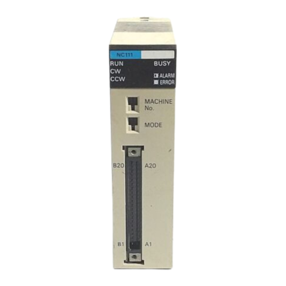
Section 1–3 System Configuration Indicators RUN: indicates operation BUSY: indicates operation/transfer is in progress is in progress CW: indicates controlled system ALARM: blinks when an abnormality (motor) is revolving clockwise has occurred CCW: indicates controlled system ERROR: lights when an error has oc- (motor) is revolving counterclockwise curred Setting switches... -
Page 16: Control System Principles
(e.g., control panel switches). (A list of Position Control Unit inputs and outputs can be found under I/O Circuits in 2–2 Wiring.) The following configu- ration diagrams show only the positioning system itself. Refer to the operat- ing manuals for other Omron control devices for details on extended control system operation. -
Page 17: Control System Principles
Section 1–4 Control System Principles C200H PC Position Control Unit C200H-NC111 Input Unit Stepping motor (or ser- vomotor) driver control signal line Hand-held Programming Power supply Console C200H-PRO27 Operation panel Operation switch Stepping motor driver (or servomotor driver) Control signal input switches Stepping motor (or servomotor) 1–4... -
Page 18: Open-Loop System
Section 1–4 Control System Principles to bring them more closely in line with target values. In some systems, the digital feedback signals will be transmitted to a digital-to-analog converter to complete the feedback loop, thereby permitting automated control of the process. -
Page 19: Semi-Closed-Loop System
Section 1–4 Control System Principles Data Flow Position Control Unit C200H-NC111 Stepping motor driver Pulse train Stepping motor Pulse gen- C200H PC erator External input interface Magnetizing Power distribution amplifier circuit I/O connector Memory Pulse train Servomotor driver Servomotor Error counter Power amplifier (Positioning output) Tachogenerator... - Page 20 Section 1–4 Control System Principles frequency of the pulse train. Angle of rotation Angle of rotation Positioning output Positioning pulse Simplified Positioning System Design The following diagram and parameters illustrate a simplified positioning sys- tem. Reduction gear Feed screw pitch Object being positioned Stepping motor...
- Page 21 Section 1–4 Control System Principles tation amounts, for example, computes the error between the target value and actual movement value, and zeroes the error through feedback. The dia- gram below illustrates the basic configuration of a semiclosed-loop system. Servomotor driver Servomotor Target position Error counter...
-
Page 22: Before Operation
SECTION 2 Before Operation Before the Position Control Unit can be operated, switch settings and wiring must be correct. This section presents the settings and functions of switches, provides examples of and precautions for wiring, and gives dimensions of Units both when mounted and unmounted. -
Page 23: Switch Settings
Section 2–1 Switch Settings 2–1 Switch Settings Always turn off PC power before setting the unit number switch. Use a regu- lar screwdriver, being careful not to damage the slot in the screw. Be sure not to leave the switch midway between settings. Switch Function Used to set the unit number (between 0 and 9). -
Page 24: Wiring
Section 2–2 Wiring 2–2 Wiring External I/O Connections The example diagram below shows I/O connections. Position Control Unit C200H-NC111 C200H PC Control panel Emergency stop External interrupt switch switch Input Mechanical system Origin switch (sensor) Origin proximity switch CCW limit switch Motor Output CW limit... - Page 25 Section 2–2 Wiring Connector Pin Arrangement The following I/O connector pin arrangement is as viewed from the front of the Position Control Unit. Pin no. Row B Row A Emergency stop input (0 V) Emergency stop input (12 to 24 VDC) Emergency interrupt input (0 V) External interrupt input (12 to 24 VDC) CW limit input (0 V)
- Page 26 Section 2–2 Wiring Connector Pin Numbers The connector pin numbers are shown in the following figure. Wire the connector correctly according to the pin numbers. Shape of connector flange on other side Insulator Lead (0.3 mm max.) Pin number marks Connector Connector Viewed from Soldered Side Differentiating Cables...
- Page 27 Section 2–2 Wiring Outputs Constant- Supply a voltage of either voltage 5 or 24 VDC; the internal Power for output, 24 VDC circuit circuit will be damaged if both the power sources Power for output, 5 VDC are connected. Ω 1.6 k (1/2W) Ω...
- Page 28 Section 2–2 Wiring Input Connection Example Each input is provided with both a N.O. (normally open) input or N.C. (nor- mally closed) input that can be used according to specifications. Leave unused N.O. inputs open and connect unused N.C. inputs to the power supply.
- Page 29 Section 2–2 Wiring Output Connection Examples The following figures illustrate examples of connections to motor drivers. Al- ways confirm motor driver specifications before making connections. The Unit outputs only pulse trains and a direction output, or separate CW and CCW pulse trains, to control the motor driver. If other control signals, such as a deflection counter reset signal or motor excitation release signal, are required, use a C200H I/O Unit and program in the required control ac- tions.
- Page 30 Section 2–2 Wiring Example 1: Outputting CW and CCW Pulses With a 5-VDC Power Supply 5-VDC (Do not share this power supply with other pins.) power Position Control Unit supply Motor driver (rated at 5 VDC) – Ω (Example: R = 220 24 VDC input 5 VDC input Ω...
- Page 31 Section 2–2 Wiring Example 2: Outputting CW and CCW Pulses With a 24-VDC Power Supply and a Motor Driver Rated at 5 VDC 24-VDC (Do not share this power source with other pins.) power supply Position Control Unit Motor driver (rated at 5 VDC) –...
- Page 32 Stepping motor UPH599 –CW +CCW –CCW Power for output 5 VDC Limit switch (N.O. or N.C. contact) Origin proximity Origin OMRON Photoelectric Switch E3S-X3 CE4 Signal (NPN output type) 24 V/0 V Limit switch (N.C. contact) limit CW limit Emergency stop...
- Page 33 (N.O or N.C.) 12 to 24 VDC Origin proximity Ω 50-75 Origin Toshiba TLP521-1 (GB) Signal Photocoupler 24 V/0 V OMRON E3S-X3 CE4 (NPN output) Photoelectric switch 12 to 24 VDC CCW limit CW limit Emergency stop N.C. limit switches Wiring Precautions Operational errors can occur in most electronic control devices if they are subjected to electronic noise from nearby power lines or loads.
- Page 34 Section 2–2 Wiring DC relays AC relays Diode for surge absorption Surge absorber – Note: Connect the diode and surge absorber as close as possible to the relay. Use a diode capable of withstanding a voltage five times higher than the circuit voltage.
-
Page 35: Dimensions
Section 2–3 Dimensions 2–3 Dimensions Unit Dimensions (Unit: mm) 100.5 Mounted Dimensions (Unit: mm) Rack Cable Approx. 200... -
Page 36: Operation
SECTION 3 Operation This section covers all aspects of Position Control Unit operation other than commands, which are covered in the follow- ing section. Included in this section are the basic operating procedure, the type of output pulses possible, the basic data format and configuration, some special features to aid operation, such as flags, zone settings, backlash compensation and internal limits, and the internal data calculation methods used in processing user-input data. -
Page 37: Operational Flow
Section 3–1 Operational Flow 3–1 Operational Flow The basic procedure used to initially operate the Unit is outlined below. Refer to applicable sections of the manual for details on each of these steps. Item Procedure Refer to: Start Wiring 2–2 Wiring Origin, origin proximity, CW/CCW Wiring external limits, emergency stop, external in-... - Page 38 Section 3–1 Operational Flow Procedure Item Refer to: Trial run Position Control Restart by resetting 6–4 Troubleshooting power or AR area Unit reads DM area From the PC restart bit AR area error and restart bits for Special I/O Units ORIGIN SEARCH, manual operation, start, etc.
-
Page 39: Output Pulses
Section 3–3 Writing Data 3–2 Output Pulses The Position Control Unit can be set to output either independent CW and CCW pulses or a nondirectional pulse and a direction signal. Set pin #1 on the back-panel DIP switch to designate the target type of output. (See 2–1 Switch Settings.) CW and CCW Pulse Outputs... -
Page 40: Data Configuration And Allocation
Section 3–4 Data Configuration and Allocation tails.) The busy flag and present position status can be read out from the IN refresh area, the last five of these words. To start the Unit, set (i.e., turn ON) the command bit regardless of whether the Unit is in RUN or PROGRAM mode. - Page 41 Section 3–4 Data Configuration and Allocation Data Configuration C200H PC Position Control Unit IR Area I/O refresh data areas Words 100 to 109 Unit #0 Words n to (n+4) OUT refresh Words 110 to 119 Unit #1 Words (n+5) to (n+9) IN refresh Words 120 to 129 Unit #2...
- Page 42 Section 3–4 Data Configuration and Allocation IR Area Allocations ”n” is the first IR word allocated to the Unit and equals 100 plus 10 times the unit number. Word START Initial Speed PC data area (for Valid initial positioning positioning coefficient TRANSFER DATA) action number...
-
Page 43: Ir Area Data Format
Section 3–5 IR Area Data Format Word Positioning completed flag Present position Bank completed flag Positioning (rightmost 4 action no. digits) At-origin flag Direction digit Alarm flag Emergency stop flag Present position (leftmost 3 digits) Error flag Error code Zone 0 flag Zone 1 flag Zone 2 flag Teaching completed flag... -
Page 44: Flags And Other Input Data
Section 3–7 DM Area Allocation Speeds Acceleration and Deceleration Data Coding Although decimal notation is generally used for data in this manual, data is handled in the system as binary-coded decimal (BCD) unless otherwise noted. Note that this data is generally input as decimal, whereas hexadeci- mal data is input as hexadecimal. - Page 45 Section 3–7 DM Area Allocation Function Function Function Transfer no. Transfer no. Initial position nos.; speed nos. Positioning Positioning Origin compensa- action #4 action #15 tion and direction Backlash com- pensation Positioning Positioning action #5 action #16 limit Positioning Positioning limit action #6 action #17...
- Page 46 Section 3–7 DM Area Allocation 3–7–1 Zones Up to three zones can be set in the DM area. If one or more zones have been set, zone flags in the IR area can be used to determine if the present position is within any established zones.
- Page 47 Section 3–7 DM Area Allocation Zone Flags When the present position is in one or more of the zones, zone flags in the IR area are turned ON (1). The PC’s scan time, however, can produce a delay in indication during pulse output. Flag allocations are as follows: 07 06 Zone 0 flag 0 Outside zone...
- Page 48 Section 3–7 DM Area Allocation Using Backlash Compensation When the feeding direction is reversed, the number of pulses set in DM area is output at the initial speed, and the Unit then proceeds with normal opera- tions. Í Í Time Í...
- Page 49 Section 3–7 DM Area Allocation If either of these limits is reached during execution of positioning actions, pulse output will stop, and an error code, either 5030 or 5031, will be gener- ated. Manual Operation If either of these limits is reached during execution of LOW-SPEED JOG, HIGH-SPEED JOG, or INCH, pulse output will stop, and an error code, either 5070 or 5071, will be generated.
- Page 50 Section 3–7 DM Area Allocation Settings between 1 and 200 pps 62,500 Actual speed (pps) = INT(62,500/set value) Pulse output (actual speed) 62.5 KHz Divider A 62.5-KHz source clock is divided by the integral divider ratio. Example Values Set Value (pps) Actual Speed (pps) 200.32 120.19...
- Page 51 Section 3–7 DM Area Allocation Table Creation The internal processing of the Position Control Unit is as follows during table creation. The speed difference, ∆V, is obtained to express the range of speed set- 1, 2, 3... 1. tings. ∆ V = MAX –...
- Page 52 Section 3–7 DM Area Allocation ∆ V = 20000 x 2 = 40000 ∆ L = ( V/R) = (40000/100) = 100 ∆υ = 40000/100 = 400 υ ( Speed) 4 ms 40000 39600 R = 400= 100 39200 38800 20400 20000 19600...
- Page 53 Section 3–7 DM Area Allocation The value of ”k” depends on the number of transfers being made, as illus- trated in the following table. Number of transfers 1 to 6 7 to 13 14 to 20 21 to 26 Influence on PC Scan Time Mounting one Position Control Unit on a PC extends the PC’s scan time by about 3 ms.
-
Page 54: Commands
SECTION 4 Commands The Positioning Control Unit provides thirteen commands to execute automatic and manual positioning actions, define and establish position, transfer data, and handle interrupts and errors. Although the data required for execution is listed under each command, much of this data is used by more than one command. Refer to 3–4 Data Configuration and Allo- cation for an outline of the structure of Unit data, and to 3–5 IR Area Data Format for format specifications for particular types of data. -
Page 55: Start
Section 4–1 Start 4–1 Start The START command bit, bit 00 of word n, is set to begin execution of posi- tioning actions (effective on signal’s rising edge). The actions are executed in order from either the initial positioning action designated in the DM area or that designated in the IR area. - Page 56 Section 4–1 Start Target speed Target speed Acceleration Acceleration Time Initial speed #0 Initial speed number other than 0 Speeds DM words m+82 through m+96 Set each word to a value between 0000 and 9999 pps (4 digits) Each of these values, when multiplied by the relevant speed unit in word m+97, is referred to by number to set speeds for this and several other com- mands.
- Page 57 Section 4–1 Start Positioning actions (or sequences) consist of a completion code, dwell time, output code, speed number, and target position. These actions are generally referred to by number and completion code. For example, ”#6, continuous” indicates positioning action #6 with a completion code of 2 (continuous). The settings for positioning action #0, DM words m+22 through m+24, are ex- plained below.
- Page 58 Section 4–1 Start 2: Continuous As soon as the target position for the first positioning action is reached, the next positioning action is started. The first target position is reached at the target speed set for the next positioning action, so that the next positioning action can be executed immediately.
- Page 59 Section 4–1 Start The next action can be executed when the busy flag turns OFF after the dwell time has expired. In other words, the positioning completed flag re- mains OFF and the busy flag remains ON until the dwell time has expired. (See 4–1–3 Execution Examples.) Output Code DM word m+22, bits 11-08...
-
Page 60: Ir Area Settings
Section 4–1 Start 24 is used as a direction digit. (See Appendix C DM Area Allocations.) m+23 x10 m+24 m+23 Direc- Sign m+24 tion CW absolute value CCW absolute value CW increment CCW increment Maximum values are as follows: 8388606 pulses CCW: 8388607 pulses Absolute values are measured from the origin. - Page 61 Section 4–1 Start tions. 01 00 START Valid initial positioning action number Valid speed coefficient STOP START word n, bit 00 When bit 00 is ON (i.e., set at 1), bits 01 and 07 are referred to and position- ing begins. Valid Initial Positioning Action Number word n, bit 01...
-
Page 62: Execution Examples
Section 4–1 Start Speed Coefficient word n+2, bits 07-00 Set a value between 00 and 20 (in units of 0.1). In other words, a setting of 15, for example, will represent an actual value of 1.5. This coefficient is valid if bit 07 of word n is 1 when the START command bit (bit 00 of word n) is set. - Page 63 Section 4–1 Start START START START Pause positioning axis START Initial position The completion code for positioning action #0 is set at 0, making it a single action. Positioning stops after completion of this action, and START is neces- sary for operation to begin again. The completion codes for positioning actions #1 and #2 are set at 2, making them continuous actions.
- Page 64 Section 4–1 Start Completion code Single m+22 Positioning action #0 Pulse output Continuous Time Positioning m+25 action #1 START Stop Continuous Positioning m+28 action #2 Single Positioning Pulse output m+31 action #3 Time Pause Positioning START Stop m+34 action #4 Single Positioning m+37...
- Page 65 Section 4–1 Start Example 2: Using Dwell Time In this example, the completion code for positioning action #1 is set at 1 (pause), with the dwell time set at 0.5 s. The completion code for positioning action #2 is set at 0 (single), with the dwell time set at 1.0 s. START (word n, bit 00) Pulse output...
-
Page 66: Origin Search
Section 4–2 Origin Search START command word n, bit 00 #1, continuous #2, single Pulse output #0, single Time Positioning completed flag word n+5, bit 00 Busy flag word n+5, bit 12 Positioning action number word n+7, bits 07-00 When positioning ends, the positioning action number is changed as follows: Output code word n+7, bits 08-11... -
Page 67: Ir Area Settings
Section 4–2 Origin Search ORIGIN SEARCH Proximity Speed Number (Low Speed) DM word m+1, bits 03-00 Set to an integer between 1-F (hex). The speed number set here refers to one of the speeds set in DM words m+82 through m+96. It cannot be set higher than the ORIGIN SEARCH high speed number. -
Page 68: Execution Examples
Section 4–2 Origin Search In the IR area, the ORIGIN SEARCH command is set with bit 02 of word n. ORIGIN SEARCH begins when this bit is turned ON. (n = 100 + 10 x unit number) ORIGIN SEARCH command bit (ORIGIN SEARCH is started at the leading edge of this bit.) 4–2–3... - Page 69 Section 4–2 Origin Search then begins searching in the search direction. Origin proximity signal Origin signal Proximity speed Positioning axis Search direction (CCW) Origin (Stop) ORIGIN SEARCH (Begin) Example 3 When reaching the CW or CCW limit during ORIGIN SEARCH, the Unit pauses for 0.5 s, returns beyond the activation point for the origin proximity signal, and then begins searching in the search direction.
- Page 70 Section 4–2 Origin Search patterns only by eliminating accelerations and decelerations. All other as- pects remain the same. Example 1 The first diagram illustrates the simplest search pattern, as in Example 1 above. Origin signal Proximity speed Positioning axis Origin (Stop) ORIGIN SEARCH (Begin) Search direction (CCW) Example 2...
-
Page 71: Completion Examples
Section 4–2 Origin Search 4–2–4 Completion Examples Completion Patterns With an Origin Proximity Signal The following two example diagrams both illustrate completion of ORIGIN SEARCH when an origin proximity signal is present (i.e., when DIP switch no. 3 is ON). There is an origin compensation value set in the second exam- ple, but not in the first. - Page 72 Section 4–2 Origin Search Example 2: With Origin Compensation Origin proximity signal Origin signal Deceleration Pulse output Proximity speed High speed Time Movement equivalent to compensation value 0.5 s At-origin flag word n+5, bit 02 No-origin flag word n+5, bit 11 Busy flag word n+5, bit 12...
- Page 73 Section 4–2 Origin Search Completion Patterns Without an Origin Proximity Signal The following two example diagrams both illustrate completion of ORIGIN SEARCH when no origin proximity signal is present (i.e., when DIP switch no. 3 is OFF). There is an origin compensation value set in the second exam- ple, but not in the first.
-
Page 74: Origin Return
Section 4–3 Origin Return Example 2: With Origin Compensation Origin signal Proximity speed Pulse output Time Movement equivalent to compensation value 0.5 s At-origin flag word n+5, bit 02 No-origin flag word n+5, bit 11 Busy flag word n+5, bit 12 4–3 Origin Return The ORIGIN RETURN command bit, bit 03 of IR word n, is set to return to... -
Page 75: Ir Area Settings
Section 4–3 Origin Return 4–3–2 IR Area Settings The ORIGIN RETURN command is valid when bit 03 of word n is ON. (n = 100 + 10 x unit number) ORIGIN SEARCH command ORIGIN SEARCH is started at the leading edge of this bit.. 4–3–3 Execution Example ORIGIN RETURN can only be executed when the origin (0) is known. -
Page 76: Release Prohibit
Section 4–4 Release Prohibit 4–4 Release Prohibit When Position Control Unit operation is stopped as a result of input of an emergency stop, CW limit, or CCW limit signal, (i.e., when the N.C. input of any of these turns ON), further pulse output is prohibited. In order to resume pulse output, it is necessary to cancel this prohibition by means of the RE- LEASE PROHIBIT command bit (bit 04 of word n) and release of the external emergency stop switch. -
Page 77: Execution Examples
Section 4–4 Release Prohibit 4–4–1 Execution Examples Example 1: Emergency Stop The present position is lost during an emergency stop, and positioning can- not be started again directly after RELEASE PROHIBIT. Execute ORIGIN SEARCH before proceeding. Input Emergency stop signal START word n, bit 00 RELEASE PROHIBIT... - Page 78 Section 4–4 Release Prohibit Example 2: Exceeding CW or CCW Limit The emergency stop flag is not affected by exceeding the CW or CCW limit. When a limit is exceeded, only pulse output in the opposite direction is possi- ble. In other words, when the CW limit is exceeded, only CCW pulse output is possible.
-
Page 79: Read Error
Section 4–5 Read Error 4–5 Read Error The READ ERROR command bit, bit 05 of word n, is set to access error and alarm codes when more than one of these is present (effective on signal’s rising edge). The codes are consecutively output to word n+6. Errors and alarms have separate flags, as follows: Alarm flag: Set to 1 when an alarm code has been generated... -
Page 80: Reset Origin
Section 4–7 Teach 4–5–2 Reading from the Programming Console The following example diagram (for Unit #1) shows how to read an alarm/er- ror code from the Programming Console. Programming Console Display: Key sequence: C106 1501 10005 C106 ^OFF 1501 10005 C106 ^OFF 5000 4–6... -
Page 81: Ir Area Settings
Section 4–7 Teach Present positioning axis position DM 1052 DM 1053 DM 1054 Data set using TEACH is valid immediately and can be used for positioning actions without turning off the power or transferring data. Note that data re- written using the Programming Console is not valid until data has been trans- ferred again. -
Page 82: Execution Example
Section 4–8 Transfer Data 4–7–2 Execution Example TEACH positioning action no. word n+1, bits 15-08 TEACH word n, bit 09 Teaching completed flag word n+5, bit 09 Busy flag word n+5, bit 12 4 scans max. 4–7–3 Teaching from the Programming Console The following example shows how to teach positions from the Programming Console for Unit #0. -
Page 83: Transfer Data
Section 4–8 Transfer Data area, and this data is automatically transferred. TRANSFER DATA, however, can transfer data from other parts of the DM area as well as from the LR, HR, and other areas. C200H PC Position Control Unit #5 Data table DM 1500 to 1599 Automatically transferred at... -
Page 84: Ir Area Settings
Section 4–8 Transfer Data fected. Parameters set in DM words m through m+21 are not changed when TRANSFER DATA is executed. Data Preparation Up to 26 transfers (three words each) can be made each time TRANSFER DATA is executed. Each transfer consists of one positioning action, three speeds, or the speed units, acceleration, and deceleration. - Page 85 Section 4–8 Transfer Data Beginning Transfer Num- word n+2, bits 15-08 Set an integer between 00 and 25. This number indicates the position where the first transfer is to be made. The designated number of transfers will be transferred continuously from this point.
-
Page 86: Present Position Preset
Section 4–8 Transfer Data Execution Example (Normal Transfer) This example assumes that bit 15 of word n+2 is 0. Preparation of data in PC’s data areas Set necessary information in IR area. Beginning transfer number word n+2, bits 15-08 Beginning word number word n+3 PC data area/no. - Page 87 Section 4–8 Transfer Data to either the HR or DM area, and then restore by using TRANSFER DATA the next time the Unit is powered up. The following programming example shows word n+8 data moving to word HR 00 and word n+9 data moving to word HR 01. If there is no origin, bit 11 of word n+5 (the no-origin flag) turns ON (goes to 1).
- Page 88 Section 4–8 Transfer Data PC Data Area word n+4, bits 07-00 Set the data area (in four digits BCD) from which the transfer is to be made. Beginning word number Data Area Set a word Number of transfers number in 4-digit BCD code TRANSFER DATA...
-
Page 89: Manual Operations
Section 4–9 Manual Operations Execution Example (Preset) The following example assumes that bit 15 of word n+2 has been set to 1. Set necessary information in IR area. Present position preset word n+2, bit 15 Beginning word number word n+3 PC data area word n+4 bits 07-00 TRANSFER DATA... -
Page 90: Ir Area Settings
Section 4–9 Manual Operations SpeedsDM words m+82 through m+96 Speed Units DM word m+97 Acceleration Bits 11-00 of DM word m+98 Deceleration Bits 11-00 of DM word m+99 HIGH-SPEED JOG Speed Number word m+1, bits 15-12 Set an integer between 1 and F (hex). The speed number set here refers to one of the speeds set in DM words m+82 through m+96. -
Page 91: High-Speed Jog
Section 4–9 Manual Operations 4–9–3 High-speed Jog The HIGH-SPEED JOG command bit (word n, bit 11) of is set to manually feed at the designated speed (effective on signal’s rising edge). Feeding starts when the command bit is set and continues until it is reset. HIGH-SPEED JOG word n, bit 11 HIGH-SPEED JOG speed... -
Page 92: 4-10 External Interrupt Commands
Section 4–10 External Interrupt Commands 4–9–5 Inch The INCH command bit, bit 14 of word n, is set to manually inch one pulse at a time (effective on signal’s rising edge). One pulse will be feed each time this bit is set. INCH word n, bit 14 1 pulse (2.5 ms) -
Page 93: 4-10-1 Stop
Section 4–10 External Interrupt Commands Connection for External Interrupt Signal The signal level’s rising edge is taken as the input signal. External input pin no. DC power supply 24 V External interrupt signal Interrupt signal received DIP Switch Settings The setting of pin #6 on the back-panel DIP switch determines the function of bit 06 of IR word n. - Page 94 Section 4–10 External Interrupt Commands STOP Executed During START When the STOP command bit is set during execution of a positioning action under START, the positioning completed flag is not turned ON, and the posi- tioning action number is not changed. When START is next executed, the target position and speed of that action will be used, as long as the target position has not been exceeded.
- Page 95 Section 4–10 External Interrupt Commands Example 2 This example shows STOP execution if the target position is not exceeded when the target position is designated from the origin (i.e., not an increment). When START is next executed, the data from the positioning action at the time of STOP is taken as the target position.
- Page 96 Section 4–10 External Interrupt Commands Example 3 This example shows execution when a target position designated from the origin (i.e., not an increment) is exceeded during deceleration for STOP, as can happen when STOP is executed during the end of a continuous position- ing action.
- Page 97 Section 4–10 External Interrupt Commands Example 4 When the target position is expressed as an increment, the positioning action will be automatically started over from the position arrived at after STOP was executed. START word n, bit 00 STOP word n, bit 15 Pulse output Time Positioning completed flag...
- Page 98 Section 4–10 External Interrupt Commands STOP During ORIGIN SEARCH Feeding will be decelerated to a stop and the command must be reexecuted from the position reached at the end of STOP. STOP During ORIGIN RETURN Feeding stops according to the deceleration rate. ORIGIN RETURN word n, bit 03 STOP...
- Page 99 Section 4–10 External Interrupt Commands STOP During HIGH-SPEED JOG If STOP is executed during HIGH-SPEED JOG, feeding will be stopped just as if the HIGH-SPEED JOG command bit (word n, bit 11) were reset to 0. The command bit, however, will remain at 1. HIGH-SPEED JOG word n, bit 11 STOP...
-
Page 100: 4-10-2 Change Speed
Section 4–10 External Interrupt Commands STOP During LOW-SPEED JOG If STOP is executed during LOW-SPEED JOG, feeding will be stopped just as if the LOW-SPEED JOG command bit (word n, bit 13) were reset to 0. The command bit, however, will remain at 1. HIGH-SPEED JOG word n, bit 11 STOP... - Page 101 Section 4–10 External Interrupt Commands Execution Example In the following example diagram, speed number 1 is used for the positioning action executed first. START word n, bit 00 CHANGE SPEED (external interrupt input or word n, bit 06) Speed #4 Speed #1 Speed #2 Speed #3...
-
Page 102: Programming Examples
SECTION 5 Programming Examples This section contains examples of possible applications of Positioning Control Unit commands, inputs, and outputs. Ex- ample 1 shows the minimum data required for operation. Example 2 shows the use of only one positioning action under START augmented by RESET ORIGIN. -
Page 103: Operation With Minimum Data: Displaying Jog Positions
Section 5–1 Operation with Minimum Data: Displaying JOG Positions 5–1 Operation with Minimum Data: Displaying JOG Positions Wiring The wiring shown below is the simplest possible for Position Control Unit op- eration. Hand-held Programming Console Position Control Unit #0 C200H PC C200H-PRO27-E Emergency stop CW limit... - Page 104 Section 5–1 Operation with Minimum Data: Displaying JOG Positions C109 C108 0999 9911 Monitor the RESET ORIGIN command bit. 10008 C109 C108 ^ OFF 0999 9911 Reset the present position. 10008 C109 C108 ^ OFF 0000 0000 Set LOW-SPEED JOG command bit. Indicators on Position Control Unit Programming Console Display NC111...
-
Page 105: Positioning At Intervals: Using Reset Origin
Section 5–2 Positioning at Intervals: Using RESET ORIGIN 5–2 Positioning at Intervals: Using RESET ORIGIN In this example, the Position Control Unit is assumed to be assigned unit number 0. Configuration Position Control Unit C200H PC Emergency stop CW limit CCW limit Origin Origin... - Page 106 Section 5–2 Positioning at Intervals: Using RESET ORIGIN Programming ORIGIN Initial Initial RETURN speed position speed Start switch 1 to F 0 to F 0 to 19 DIFU 3000 DM 1000 1 0 0 0 HIGH- LOW-S ORIGIN Origin Busy (flag) DM 1001 1 2 1 2 SPEED...
-
Page 107: Feeding Selectively With Start
Section 5–4 Transfer Data from Other PC Areas 5–3 Feeding Selectively with START Configuration Ladder Diagram With the following programming, input A, B or C can be selected and START executed to feed the target number of pulses. Origin reset switch 10008 RESET ORIGIN 25313... - Page 108 Section 5–4 Transfer Data from Other PC Areas Data To Be Transferred The transfer data is entered in DM words 0010 to 0018. The data and posi- tioning actions are shown below. DM 0010 3 0 0 2 DM 1084 DM 0011 9 0 0 0 Speed #3...
- Page 109 Section 5–4 Transfer Data from Other PC Areas Program 00407 (Transfer PB) DIFU (13) 04001 Transfers data from DM 0010 when 00407 is set. Re-transfers data from DM 1022 when 00407 is reset. DIFU (14) 04002 (Three positioning actions transferred, beginning with 04001 DM 0010) MOV (21)
-
Page 110: Transfer Data From External Switches
Section 5–5 Transfer Data from External Switches 5–5 Transfer Data from External Switches In this example, positioning is executed in accordance with the number of pulses set by external thumbwheel switches. Configuration Word 0 Word 2 Word 3 Positioning C200H 16 bits 16 bits 16 bits... - Page 111 Section 5–5 Transfer Data from External Switches Program (SW 1) (SW 2) 00010 00000 DIFU (13) 03000 Data transfer switches (SW 2) (SW 1) 00000 00010 DIFU (13) 03001 Start switches 03000 10512 03002 MOV (21) Beginning action no. #0000 (busy flag) Origin re- (positioning action #0).
-
Page 112: Using Start To Carry Out Positioning Actions
Section 5–6 Using START to Carry Out Positioning Actions 5–6 Using START to Carry Out Positioning Actions Wiring (Details Omitted) PRO27-E ID211 ID212 OD211 NC111 OUT, 8 bits 16 points 12 points Position Control C200H Unit #0 Motor Driver Word 0 Word 1 Word 2 100 words... - Page 113 Section 5–6 Using START to Carry Out Positioning Actions Feeding Pattern 2000 1000 #0, single #1, single 10000 20000 4000 4000 4000 3000 T = 0.5 s T = 1.0 s T = 1.0 s #3, pause #5, single #2, pause #4, pause 30000 40000...
- Page 114 Section 5–6 Using START to Carry Out Positioning Actions Program 00000 10002 ORIGIN SEARCH 00001 RELEASE PROHIBIT 10004 00002 JOG direction 10012 00003 10011 HIGH-SPEED JOG 00004 10013 LOW-SPEED JOG 00005 10000 START 00006 10001 Valid initial positioning action number 00007 10015 STOP...
- Page 115 Section 5–6 Using START to Carry Out Positioning Actions Function Function W 15 Function Transfer no. Transfer no. Initial position nos.; 1 0 1 speed nos. 2 3 4 Positioning Positioning Origin com- 2 0 0 action #4 action #15 pensation and direction 0 0 0...
-
Page 116: Using Origin And Origin Proximity Signals
Section 5–7 Using Origin and Origin Proximity Signals 5–7 Using Origin and Origin Proximity Signals Configuration Position Control Unit C200H PC Emergency stop CW limit CCW limit Origin Origin proximity 24 VDC DIP Switch Settings Pin 3 ON (Designating presence of origin proximity signal) Pin 4 ON (Designating N.O. -
Page 117: Using Zones To Control Jogging
Section 5–8 Using Zones to Control Jogging Operation ORIGIN SEARCH 10002 The possible search patterns for ORIGIN SEARCH using both an origin sig- nal and an origin proximity signal are as follows. Origin proximity signal Pulse output START Origin (Stop) START Origin (Stop) START... -
Page 118: Controlling An R88D-Ep06 Servodriver
JOG direction 5–9 Controlling an R88D-EP06 Servodriver In this connection example, an Omron R88D-EP06 Servodriver is used, and wiring employs the origin adjustment function of this model. The example demonstrates how to use a faster ORIGIN SEARCH proximity speed and yet increase ORIGIN SEARCH accuracy. - Page 119 Section 5–9 Controlling an R88D-EP06 Servodriver OMRON R88D-EP06/EP12 Servodriver (marketed in Japan) Position Control Unit –CW +CCW OMRON R88M-E –CCW Servomotor N.C. switches (or short circuit) Power for output +5 VDC 5 VDC 27 H RET Origin 12 to 24 VDC...
- Page 120 Section 5–9 Controlling an R88D-EP06 Servodriver Timing Chart Z-phase Origin proximity (10715) 00200 (Servodriver origin adjustment input) Servodriver positioning completed signal Pulse output DIP Switch Settings Pin 1: Pin 2: ON or OFF Pin 3: Pin 4: Pin 5: Pin 6: Pin 7: Pin 8:...
-
Page 121: 5-10 Controlling A V-Series Servodriver
Section 5–10 Controlling a V-series Servodriver Program ORIGIN SEARCH DIFU (13) 04900 04904 04900 10512 (busy flag) ORIGIN SEARCH and IL ON 10002 signal during ORIGIN SEARCH 10002 10002 ORIGIN SEARCH IL (02) being executed 04902 10513 (CW limit) Prohibits the origin adjustment command 04901 from being output when origin proximity signal is OFF during reverse feeding... -
Page 122: Error Processing
SECTION 6 Error Processing 6–1 Alarms and Errors ............6–2 Outputs to the IR Area . -
Page 123: Alarms And Errors
Section 6–4 Troubleshooting from the PC 6–1 Alarms and Errors Alarms Whenever the Position Control Unit is powered up, or data is transferred into the Unit, checks are performed to ensure that the data is in proper form and can be used for operation. If an error exists in speed or positioning action data at this time, an alarm code is generated. -
Page 124: Error List For Special I/O Units
Section 6–4 Troubleshooting from the PC 6–4–1 Error List for Special I/O Units Causes of Abnormality and Correction Error Operating Status Waiting for Special I/ Special I/O Unit has a hardware Replace the abnormal Special I/O Unit malfunction. with a new Unit. O Unit start-up. - Page 125 Section 6–4 Troubleshooting from the PC Restart Bits The following restart bits are turned off, on, then back off again to restart Special I/O Units. It is not necessary to turn off power to the Unit when its restart bit is used. Unit Number AR 1000 AR 0101...
-
Page 126: Basic Troubleshooting Chart
Noise a conceivable cause. Check according to wiring precautions at the end of Wiring. Malfunction in hardware Malfunction in motor or possible. motor driver possible. Contact Omron agent and Contact Omron agent. replace component. -
Page 127: Detection Of Abnormal Pulse Outputs
Section 6–6 Detection of Abnormal Pulse Outputs 6–6 Detection of Abnormal Pulse Outputs The Position Control Unit outputs pulse trains in accordance with the pro- grammed data. When tracing an abnormality, the following should be taken into consideration. Number of Pulses in Pulse Train The Unit only outputs the number of pulses required to reach the desired po- sition. - Page 128 Section 6–6 Detection of Abnormal Pulse Outputs Connections to an Up/Down Counter Position Control Unit Driver CW pulse CCW pulse UP/DOWN counter UP.P DOWN.P 12 V 12 V RESET...
-
Page 129: A Alarm Code List
Appendix A Alarm Code List Area Item Alarm Code Problem Initial speed BCD error 1000 There is a BCD error in the speed indicated by the initial speed number. Initial position- Limit error 1100 Initial positioning action number is not between 00 and 19. ing action no. - Page 130 Appendix A Alarm Code List Area Item Alarm code Problem High speed error 1601 ORIGIN SEARCH high speed number is 0, or there is a BCD error in the speed designated by the number. ORIGIN SEARCH Proximity speed error 1602 ORIGIN SEARCH proximity speed number is 0, or there is a BCD error in the speed designated by the number.
- Page 131 Appendix A Alarm Code List Area Problem Item Alarm code Zones Problems are identical to those for zone 0. Zone 2 CW error 1920 Zone 2 CCW error 1921 Zone 2 contradiction 1922 2000 There is a BCD error in the desired position for positioning action #0 (m+22 to m+24).
-
Page 132: B Error Code List
Appendix B Error Code List Error Error code Problem Correction Pulses cannot be output for START Read out alarm code, correct data command because of data that gener- accordingly, and TRANSFER DATA 5000 ated an alarm. This data includes the or RESTART. - Page 133 Appendix B Error Code List Error Problem Correction Error code ORIGIN RETURN ORIGIN RETURN cannot be executed disabled because of data for ORIGIN RETURN speed or backlash compensation that 5200 generated alarm. HIGH-SPEED HIGH-SPEED JOG cannot be executed Read out alarm code and correct and JOG disabled because of data for HIGH-SPEED JOG correct data accordingly.
- Page 134 Appendix B Error Code List Error Error code Problem Correction No-origin flag 6201 The origin signal is not detected between Check wiring of origin signal and CCW and CW limits. signal type (N.C. or N.O.) Feeding was stopped by origin signal input Check position of origin signal Origin signal during ORIGIN SEARCH before the proximity...
- Page 135 Appendix B Error Code List Error Problem Correction Error code ROM in PC TEACH cannot be executed because 8210 PC user program memory is ROM. Transferred posi- Beginning transfer number for TRANS- Check program. This error code 8300 tioning action no. FER DATA is not between 00 and 25.
-
Page 136: C Dm Area Allocations
Appendix C DM Area Allocations The first two digits of the word number have been eliminated from the follow- ing table. These are the same for all words and can be obtained by comput- ing the first DM word allocated to the Unit. This word, designated m, is equal to 1000 plus 100 times the unit number. - Page 137 Appendix C DM Area Allocations Word Function Zone 0: CCW side m+11 15 to 00 m+12 m+11 (7 digits BCD with direc- direction digit) tion m+12 15 to 00 0 CW 1 CCW Zone 1: CW side m+13 15 to 00 m+14 m+13 (7 digits BCD with...
- Page 138 Appendix C DM Area Allocations Word Function m+21 Not used Completion code 0: Single 3: Bank end 03 to 00 1: Pause 4: Extended 2: Continuous Dwell time 0 to F (hexadecimal) in units of 0.1 s 07 to 04 m+22 Output code 0 to F (hexadecimal)
- Page 139 Appendix C DM Area Allocations Word Function m+52 Positioning action #10 m+53 Data format same as for positioning action #0 (Transfer data #10) m+54 m+55 Positioning action #11 m+56 Data format same as for positioning action #0 (Transfer data #11) m+57 m+58 Positioning action #12...
- Page 140 Appendix C DM Area Allocations Word Function m+91 Speed #10 0000 to 9999 (BCD) 15 to 00 m+92 Transfer data #23 15 to 00 Speed #11 0000 to 9999 (BCD) m+93 15 to 00 Speed #12 0000 to 9999 (BCD) m+94 Speed #13 0000 to 9999 (BCD)
-
Page 141: D Ir Area Allocations
Appendix D IR Area Allocations Function ( : leading edge; : trailing edge) Word START: At the leading edge ( ) of this bit, the Position Control Unit references bits 01 and 07 of ch n and begins positioning. Valid initial positioning no.: When set to 1, the initial positioning no. set in bits 07 to 00 of word n+1 is valid. - Page 142 Appendix D IR Area Allocations Function ( : leading edge; : trailing edge) Word Positioning completed flag: ( : completed, : starting Bank completed flag: ( : bank completed, : starting At-origin flag: (1: stopped at origin) Alarm flag: (1: alarm) Emergency stop flag: ( : Emergency stop, : pulse output enabled...
- Page 143 Appendix D IR Area Allocations Detailed IR Area Allocation Table Word Function Positioning completed flag This bit turns OFF when positioning, ORIGIN SEARCH, or ORIGIN RETURN are started. It turns ON when positioning is completed (for single or bank end positioning actions). It does not turn when STOP is executed during operation.
- Page 144 Appendix D IR Area Allocations Word Function CW limit flag CCW limit flag These bits turn ON while the respective external signals are being input. STOP flag This bit goes ON when positioning, ORIGIN SEARCH, ORIGIN RETURN, or JOG stop in response to either an external interrupt signal or the STOP command bit (word n, bit 15).
-
Page 145: E Specifications
Appendix E Specifications General Conform to C-Series specifications. Performance Item Specifications 1 per Unit Number of axes Control system Automatic trapezoidal acceleration/deceleration system –8,388,607 pulses to +8,388,606 pulses Positions Number of positions 1 to 99,990 pps Speeds Number of speeds Acceleration/deceleration 1 to 999 pps/ms Origin proximity: Either absent, N.O. - Page 146 Appendix E Specifications Electrical Output Item Specifications ± Max. switching capacity 30 mA at 4.5 to 26.4 VDC 10%, NPN open collector Min. switching capacity 2.5 mA at 4.5 to 26.4 VDC, NPN open collector Leakage current 0.1 mA max. Residual voltage 0.4 V max.
-
Page 147: F Standard Models
Appendix F Standard Models Name Remarks Model Output current: 3 A (1.6 A to I/O Units) 100 to 120/200 to 240 C200H-CPU01-E 24 VDC C200H-CPU03-E SYSMAC NET Link Unit/SYSMAC 100 to 120/200 to 240 C200H-CPU11-E Link Unit is mountable Programming Console Vertical type, w/backlight C200H-PR027-E Programming Console and Data... -
Page 148: Glossary
Glossary absolute target position A target position given in respect to the origin rather than in respect to the present position. alarm code A four-digit code which is output to a word in the IR area to identify the type of alarm which has occurred. - Page 149 Glossary DM area A PC data area in which general operating parameters, speeds, and parame- ters for positioning actions are stored. dwell time A parameter that specifies the period of time during which positioning will stop before execution of the next positioning action following a positioning action with a pause completion code.
- Page 150 Glossary N.O. contacts Normally-open contacts. A pair of contacts on a relay that close when the relay is energized. open-loop system A control system in which operations are carried out according to pro- grammed instructions, but in which feedback is not provided for automatic adjustments.
- Page 151 Glossary pulse train A series of pulses output together. pulses Discrete signals sent at a certain rate. The Position Control Unit outputs pulses, each of which designates a certain amount of movement. Such pulses are converted to an equivalent control voltage in actual positioning. Remote I/O Master Unit The Unit in a Remote I/O System through which signals are sent to all other Remote I/O Units.
- Page 152 Glossary speed coefficient An IR area setting which determines the coefficient with regard to the target speed. speed number A number used to designate (as a parameter for an operation) one of fifteen speeds registered in memory. speed unit A word in the DM area which can be set to multiply the speed to which it is assigned by a factor of one or ten.
-
Page 153: Index
Index executed during START, 83 A–B execution examples, 84, 85, 86 TEACH, setting positioning action number, 70 absolute values, 49 TRANSFER DATA and trapezoidal tables, 39 acceleration, setting for START, 45 beginning transfer number, 72, 74 alarms, 112 beginning word number (for normal transfer), 74 alarm code list, 119–121 beginning word number (present position preset), alarm codes, 68... - Page 154 Index settings for origin signal, 105 direction signal outputs, 28 I/O circuits, wiring, 15–24 DM Area allocations, 127 I/O connector pins, 14 coding sheet, 33, 103 I/O refresh areas, 28, 29, 50 minimum data settings, 92, 99 settings for external interrupt, 82 IN refresh area, 29 transferring data from, 29 writing data into, 28...
- Page 155 Index scan time, 42 pause (completion code), 46 search patterns, 106 positioning actions with origin proximity signal, 57 bank end, 44, 47 without origin proximity signal, 58 execution example (with START), 54 continuous, 47 semiclosed–loop systems, 4, 6 errors in data for, 112 servolock, 9 extended, 47 initial positioning action number, 44, 50...
- Page 156 Index U–Z unit number, switch setting, 12 up/down counters, connections to, 117 valid initial positioning action number, setting for START, 50 valid speed coefficient, setting for STOP, 50 wiring assembling connectors, 15 connector pins, 14 external I/O connections, 13 I/O circuit diagrams, 16 I/O circuits, 15–24 input connections, 17 output connections, 18...
-
Page 157: Revision History
Revision History A manual revision code appears as a suffix to the catalog number on the front cover of the manual. Cat. No. W137–E1–04 Revision code The following table outlines the changes made to the manual during each revision. Unless noted, page num- bers refer to the previous version. - Page 158 Wegalaan 67-69, NL-2132 JD Hoofddorp The Netherlands Tel: (31)2356-81-300/Fax: (31)2356-81-388 OMRON ELECTRONICS LLC 1 East Commerce Drive, Schaumburg, IL 60173 U.S.A. Tel: (1)847-843-7900/Fax: (1)847-843-8568 OMRON ASIA PACIFIC PTE. LTD. 83 Clemenceau Avenue, #11-01, UE Square, Singapore 239920 Tel: (65)6835-3011/Fax: (65)6835-2711...
- Page 159 Authorized Distributor: Cat. No. W137-E1-04 Note: Specifications subject to change without notice. Printed in Japan 0504 This manual is printed on 100% recycled paper.
- Page 160 WHETHER SUCH CLAIM IS BASED ON CONTRACT, WARRANTY, NEGLIGENCE, OR STRICT LIABILITY. In no event shall the responsibility of OMRON for any act exceed the individual price of the product on which liability is asserted. IN NO EVENT SHALL OMRON BE RESPONSIBLE FOR WARRANTY, REPAIR, OR OTHER CLAIMS...
- Page 161 Application Considerations SUITABILITY FOR USE OMRON shall not be responsible for conformity with any standards, codes, or regulations that apply to the combination of products in the customer's application or use of the products. At the customer's request, OMRON will provide applicable third party certification documents identifying ratings and limitations of use that apply to the products.
- Page 162 Performance data given in this manual is provided as a guide for the user in determining suitability and does not constitute a warranty. It may represent the result of OMRON's test conditions, and the users must correlate it to actual application requirements. Actual performance is subject to the OMRON Warranty and Limitations of Liability.
Need help?
Do you have a question about the SYSMAC C200H-NC111 and is the answer not in the manual?
Questions and answers