Table of Contents
Advertisement
Advertisement
Table of Contents

Subscribe to Our Youtube Channel
Related Manuals for Omron SYSMAC C200H-ASC02


Summary of Contents for Omron SYSMAC C200H-ASC02
- Page 1 Cat. No. W165-E1-04 SYSMAC C200H-ASC02 ASCII Unit...
- Page 2 C200H-ASC02 ASCII Unit Operation Manual Revised September 2002...
- Page 4 OMRON. No patent liability is assumed with respect to the use of the information contained herein. Moreover, because OMRON is constantly striving to improve its high-quality products, the information contained in this manual is subject to change without notice.
-
Page 6: Table Of Contents
TABLE OF CONTENTS PRECAUTIONS ....... . . 1 Intended Audience . - Page 7 TABLE OF CONTENTS Glossary ........Index .
- Page 8 It has been assumed in the writing of this manual that the reader is already familiar with the hardware, programming, and terminology of OMRON PCs. If a review of this information is necessary, the read- er should refer to the appropriate OMRON PC manuals for assistance.
-
Page 9: Precautions
PRECAUTIONS This section provides general precautions for using the C200H Temperature Sensor Unit and related devices. The information contained in this section is important for the safe and reliable application of the C200H Temperature Sensor Unit. You must read this section and understand the information contained before attempting to set up or oper- ate the C200H Temperature Sensor Unit. -
Page 10: Intended Audience
It is extremely important that a PC and all PC Units be used for the specified purpose and under the specified conditions, especially in applications that can directly or indirectly affect human life. You must consult with your OMRON representative before applying a PC system to the above-mentioned applications. -
Page 11: Application Precautions
Application Precautions • Locations subject to corrosive or flammable gases. • Locations subject to dust (especially iron dust) or salts. • Locations subject to exposure to water, oil, or chemicals. • Locations subject to shock or vibration. Caution Take appropriate and sufficient countermeasures when installing systems in the following locations: •... - Page 12 Application Precautions • Do not apply voltages to the Input Units in excess of the rated input voltage. Excess voltages may result in burning. • Do not apply voltages or connect loads to the Output Units in excess of the maximum switching capacity.
-
Page 13: Hardware
SECTION 1 Hardware The ASCII Unit is an intelligent PC peripheral device designed to make a PC-based control system more flexible and powerful. The ASCII Unit, programmed in BASIC, can be used for statistical quality control, system monitoring, data processing, report generation, and other tasks. The ASCII Unit is a companion processor that relieves the PC of some of its housekeeping, monitoring, and decision making functions. -
Page 14: Front Panel
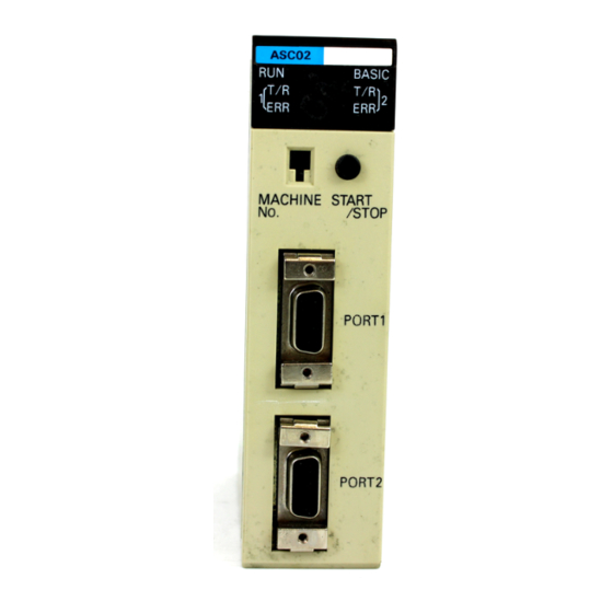
Section 1-1 Front Panel Front Panel The front panel contains two RS-232C communication ports, the program- mer’s START/STOP switch, a unit number selector, and several indicator LEDs. The back panel contains two sets of DIP switches for setting ASCII Unit parameters and the PC Backplane connector. Ports The front panel of the ASCII Unit contains two RS-232C ports. - Page 15 Section 1-1 Front Panel Front Panel ASC 02 BASIC LED Display T / R T / R Indicates the operating status of the ASCII Unit. START/STOP switch Starts/stops BASIC pro- gram execution. Machine No. switch START Sets the ASCII Unit Machine / STOP Number Machine...
-
Page 16: Back Panel
Section 1-2 Back Panel Back Panel This section explains the operations of the back panel of the ASCII Unit. There are two 8-pin DIP switches on the Backplane side of the ASCII Unit. The desired configuration must be set before the ASCII Unit can be plugged into the Backplane. - Page 17 Section 1-2 Back Panel Left-Side DIP Switch Settings 6: The pin numbers for port 2 corrected in the diagram. Screen size Pin No. Screen Size Setting 40 columns x 7 lines 40 columns x 8 lines 40 columns x 15 lines 40 columns x 16 lines 80 columns x 15 lines 80 columns x 16 lines...
- Page 18 Section 1-2 Back Panel Right-Side DIP Switch Definitions Pins 1, 2, and 3 are used for setting the baud rate of port 1. Pin 4 is not used. Pins 5, 6, and 7 are used for setting the baud rate of port 2. Pin 8 is not used.
-
Page 19: System Configuration
Section 1-3 System Configuration System Configuration If the ASCII Unit is plugged into either of the 2 CPU Backplane slots next to the CPU Unit, it will not be possible to mount a Host Link Unit or a Program- ming Device, such as a Programming Console. Before mounting the ASCII Unit, the DIP switches must be set. -
Page 20: Data Section
SECTION 2 Data Section This section explains the data section of the PC, a special memory area used to communicate with the ASCII Unit. This section also defines several important terms which are used throughout this manual. The material in this section will be- come more clear later on when you begin working with an actual ASCII Unit program. -
Page 21: Bits And Bytes
Section 2-1 Bits and Bytes Bits and Bytes The PC’s memory is divided up into many sections, each of which has its own name and purpose. The ASCII Unit can access any of these memory areas using the BASIC READ(@) and WRITE(@) statements (this is ex- plained in more detail in Section 4 BASIC Language). -
Page 22: Data Section
Section 2-2 Data Section Data Section Each ASCII Unit is assigned four memory words called the Data Section for communication with the PC. The words are assigned from addresses 100 to 199 of the PC IR memory area. How this information is used will be under- stood better after you read the BASIC Language and Programming Exam- ples sections of this manual. - Page 23 Section 2-2 Data Section Bit Definitions Word No. Name Function Output Not used (n = 100 + WRITE (PC to This bit is used as a flag. When this flag is set (”1”) and 10 x unit ASCII) the PC READ command is executed, a specified no.) quantity of data will be transferred from the PC to the ASCII Unit, starting from a specified word.
- Page 24 Section 2-2 Data Section Bit Definitions Continued Word No. Name Function Output (n = n + 2 00 to 12 Transfer base word These bits specify the PC base word (the first word 100 + 10 x from which data is accessed) for data transfer. unit no.) 13 to 15 PC memory...
-
Page 25: Programming And Communication
SECTION 3 Programming and Communication Section 3-1 explains how the ASCII Unit and the PC exchange information. Section 3-2 explains how to transfer pro- grams from one device to another. The ASCII Unit BASIC program is written on a personal computer. To run the pro- gram, it must be transferred to the RAM of the ASCII Unit. -
Page 26: Programs
Section 3-1 Programs Programs To use the ASCII Unit in conjunction with the PC, an ASCII Unit program writ- ten in BASIC is needed. A data exchange routine must also be incorporated into the PC program except when the READ(@...) and WRITE(@...) state- ments are used with specific memory area designators. -
Page 27: Program Transfer
Section 3-2 Program Transfer Program Transfer Preparation For the personal computer to communicate with the ASCII Unit, set the com- puter communication software as follows: Baud rate: same as ASCII Unit Data length: 8 bits Parity: none No. stop bits: Also: Full duplex, no echo, no XON/XOFF buffer busy control, no auto line feed. -
Page 28: Running The Basic Program
Section 3-4 Assembly Routines Direction of Data Transfer ASC 02 BASIC T / R T / R START / STOP Machine SAVE #1, “COMU:” Computer or other periph- LOAD #1, “COMU:” eral device · · · · · · Port 1 ·... -
Page 29: Section 4 Basic Language
SECTION 4 BASIC Language This section contains an explanation of the terminology, components, structure, and use of the BASIC programming lan- guage on the ASCII Unit. Even those familiar with BASIC should study this section carefully, as many of the ASCII Unit BASIC commands, statements, and functions are non-standard, especially those that control I/O operations. -
Page 30: Basic Language
Section 4-1 Program Configuration Program Configuration A BASIC program consists of commands, statements, and functions. General statement Statement Device control statement BASIC Language Command Arithmetic operation function Function Character string function Special function Basic Statements designate and control the flow of programs and are gen- erally used in program lines within a program. - Page 31 Section 4-1 Program Configuration Constants Character Decimal Numeric Integer Octal Hexadecimal Single-precision Real Number Double-precision Character Constants A character constant is a character string enclosed by double quotation marks (”). It can be up to 255 characters long. If it has no character, it is called an “empty character string”...
- Page 32 Section 4-1 Program Configuration Integer: Uses 2 bytes per variable. ! Single-precision real: Uses 4 bytes per variable. # Double-precision real: Uses 8 bytes per variable. $ Character: Uses a maximum of 255 characters. There is a second way to declare variable types. The BASIC statements DE- FINT, DEFSTR, DEFSNG, and DEFDBL may be used to declare the types for certain variable names.
- Page 33 Section 4-1 Program Configuration Example: A = 12.3: “12” is assigned to A. Expressions Expressions refer to constants, variables, and functions that have been com- bined by operators. Numeric values, variables, or characters alone can also form expressions. There are four types of expressions: •...
- Page 34 Section 4-1 Program Configuration formed after arithmetic and relational operations. The outcome of a logical operation is determined as shown in the following table. The operators are listed in the order of precedence. Logical Operator Description, Example, and Result NOT (negation) NOT A AND (logical product) A AND B...
-
Page 35: Basic Language
Section 4-2 BASIC Language A = 5 = 0000000000000101 B = 6 = 0000000000000110 A AND B = 0000000000000100 = 4 OR (logical sum) A = 4 = 0000000000000100 B = 3 = 0000000000000011 A OR B = 0000000000000111 = 7 XOR (exclusive OR) A = -4 = 1111111111111100 B = 5 = 0000000000000101... -
Page 36: Commands
Section 4-2 BASIC Language A$ and B$ : represent string expressions Remarks: Explain in detail how to use the instruction. Examples: Show sample code to demonstrate the use of the instruction. Notes: Explain additional pertinent information. 4-2-2 Commands This section describes all of the BASIC commands for the ASCII Unit. AUTO Command Purpose: To automatically generate line numbers for each line of the pro-... - Page 37 Section 4-2 BASIC Language DEL 100- Deletes all lines from line 100 DEL -150 Deletes all lines up to line 150 DEL 100-150 Deletes all lines between 100 and 150 Remarks: A period may be used in place of the line number to indicate the current line. EDIT Command Purpose: To Edit one line of the program...
- Page 38 Section 4-2 BASIC Language LIST 200- List everything from line 200 on LOAD Command Purpose: To load a program from the EPROM into memory Format: LOAD Remarks: The contents of the program area specified with the MSET Command are loaded from the EEPROM. Purpose: To load a program sent from an RS-232C device to the current program area...
- Page 39 Section 4-2 BASIC Language If no MSET address is specified, the default MSET boundary address will be set at &H2000. Do not specify an address higher than &H7FFF or the system stack will be overwritten. The address specified by this command is maintained even if system power is turned OFF.
- Page 40 Section 4-2 BASIC Language <arg> is either an integer of value 1, 2, or 3 or the character string “ALL”. ALL is entered without quotation marks. Examples: PINF 1 PINF ALL Remarks: This Command displays the amount of program area currently being used and the program names that have been assigned by the PNAME command.
- Page 41 Section 4-2 BASIC Language Format: RUN [<line>] <line> is any line number less than 63999. Remarks: If a line number is specified, execution begins from that line. If the line num- ber is omitted, execution starts from the first line of the program. The RUN command clears all variables and closes all open files before ex- ecuting the designated program.
-
Page 42: General Statements
Section 4-2 BASIC Language Format: VERIFY Remarks: If the contents of the program area are identical to those of the EEPROM, the message “READY” will be displayed; otherwise, the message “PROM ER- ROR” is displayed. 4-2-3 General Statements CLEAR Statement Purpose: To initialize numeric and character variables and set the size of the character memory area... - Page 43 Section 4-2 BASIC Language GOTO 40 IF LOC(2)<>0 THEN A$=INPUT$ (LOC(2), #2) RETURN DATA Statement Purpose: Defines numeric and character constants to be specified in a subsequent READ statement Format: DATA <constant>[,<constant>]... <constant> may be a numeric constant in any format; i.e., fixed- point, floating-point, or integer.
- Page 44 Section 4-2 BASIC Language This statement may define either numeric or string functions. If a type is spe- cified in the function name, the value of the expression is forced to that type before it is returned to the calling statement. If a type is specified in the function name and the argument type does not match, an error will occur.
- Page 45 Section 4-2 BASIC Language <subscripts> are the maximum number of elements for each di- mension of the array. There can be up to 255 subscripts but the maximum size of the array cannot exceed the amount of memory available. Example: DIM A (10,20), B$(30) Remarks: If an array variable name is used without a DIM statement, the maximum val-...
- Page 46 Section 4-2 BASIC Language <var> is used as a counter. The first numeric expression (<x>) is the initial value of the counter. The second numeric expression (<y>) is the final value of the counter. The program lines following the FOR statement are executed until the NEXT statement is encountered.
- Page 47 Section 4-2 BASIC Language GOTO 150 T = T + TIME RETURN {stuff} GOTO Statement Purpose: To unconditionally branch program execution to the specified line number Format: GOTO <line> <line> is a valid line number. Remarks: If <line> is a non-executable statement, execution will proceed at the first executable statement encountered after <line>.
- Page 48 Section 4-2 BASIC Language A comma may be used instead of a semicolon after the prompt string to sup- press the question mark. Data is not accepted by the INPUT statement until a carriage return is en- tered. Therefore input can be edited with the backspace and delete keys. When more than two variables are input, they must be delimited by commas or colons.
- Page 49 Section 4-2 BASIC Language PC READ “@D,0,1,14”;A RETURN PC WRITE “@D,0,1,14”;A RETURN LET Statement Purpose: To assign the value of an expression on the right side of an equal sign to the variable on the left side Format: [LET] <variable>=<expression> Example: LET A = 1.2 Remarks:...
- Page 50 Section 4-2 BASIC Language <m> is an integer expression from 0 to 255. <string 2> is a string expression. Example: MID$(A$,2,4) = “ABCDEFGH” Remarks: The characters in <string 1>, beginning at position <n> are replaced by the characters in <string 2>. The optional <m>...
- Page 51 Section 4-2 BASIC Language IF LOC (1)=0 THEN 120 PRINT INPUT$ (LOC(1),#1) RETURN Program Remarks: If an interrupt from port 1 is detected, the buffer contents are displayed. Note 1. If an interrupt is received on a communications line during processing of an interrupt routine, a RETURN statement will be returned and a branch will be made again to the interrupt routine.
- Page 52 Section 4-2 BASIC Language If the value of <expression> is zero or greater than the number of items in the list, execution continues with the next executable statement. If the value of <expression> is negative or greater than 255, an error message will be dis- played.
- Page 53 Section 4-2 BASIC Language <line> is any valid line number. Example: ON KEY 1 GOTO 1000 Remarks: If a statement specified by the branch line number is non-executable, execu- tion will begin with the first executable statement following the branch line number.
- Page 54 Section 4-2 BASIC Language If zero is specified as the branch line number, it is assumed that the KEY OFF statement has been executed. If the interrupt number is omitted, the same branch destination is assumed for all interrupt numbers, 1 through 15. The ON PC GOSUB statement is enabled with the PC ON statement and disabled with the PC OFF statement.
- Page 55 Section 4-2 BASIC Language ON PC 1 GOSUB 100 PC ON PC GET A, B B = Bit 10008. IF B=1 THEN PC PUT 0 If B = 1 then 10308 is turned OFF. GO TO 30 PC PUT 1 10308 is turned ON.
- Page 56 Section 4-2 BASIC Language at the highest line number will be executed regardless of which interrupt is invoked. Program Example: ON PC GOSUB 100 PC ON GOTO 30 PC READ “3I2”; A, B, C PRINT A, B, C RETURN PC PUT Statement Purpose: To write data to the PC’s ASCII Unit Data Memory Area Format:...
- Page 57 Section 4-2 BASIC Language Refer to Appendix D Formatting and Data Conversion for details on READ and WRITE statement formatting. Example: A$ = “2H1, A3, I4, O2” PC READ A$;X, Y, A$, I, J PC WRITE Statement Purpose: To write data to the PC Format: PC WRITE “<format>[,<format>...
- Page 58 Section 4-2 BASIC Language LPRINT <port> is an integer (1 or 2). <list of exp> can be numeric or character expressions. Character expressions should be enclosed in double quotation marks. Example: PRINT #1,A,B$;“BASIC” Remarks: The list of expressions must be separated by commas, semicolons, or blanks.
- Page 59 Section 4-2 BASIC Language ^^^^ Indicates the output in exponential format (E+nn). Add this character after #. “” is output before the numeric value if the specified number of digits is too great. If the port number is omitted, port 1 is assumed for the PRINT USING state- ment and port 2 for the LPRINT USING statement.
- Page 60 Section 4-2 BASIC Language Format: REM <remark> <remark> text does not need to be enclosed in quotes. Example: REM SAMPLE PROGRAM Remarks: The REM statement is used to provide titles to programs and to insert helpful comments to be used during program debugging or modification. Remarks may be added to the end of a line by preceding the remark with a single quotation mark instead of: REM.
-
Page 61: Device Control Statements
Section 4-2 BASIC Language <wait time> is the allowable time for the monitored statement to be executed. <line number> is any valid line number. Example: WAIT “10:30.5”,100 Remarks: The delay time is set in the form MM.SS.F, where: MM is the number of minutes up to 59 SS is the number of seconds F is tenths of seconds. - Page 62 Section 4-2 BASIC Language The END statement and the NEW command automatically close the ports, but the STOP statement does not. CLS Statement Purpose: To clear the screen Format: CLS [#<port>] <port> is an integer (1 or 2). Remarks: This statement clears the screen and moves the cursor to the home position. If the port number is omitted, port 1 is assumed.
- Page 63 Section 4-2 BASIC Language Signal Line XON/XOFF Valid Valid Valid Invalid Valid Valid Invalid Valid Invalid Valid Valid Invalid Invalid Invalid Valid Valid Invalid Valid Invalid Invalid Invalid Valid Invalid Invalid Invalid Valid Valid Valid Valid Valid Valid Invalid Valid Invalid Valid Valid...
-
Page 64: Arithmetic Operation Functions
Section 4-2 BASIC Language The following two tables illustrate peripheral device output levels during ex- ecution of the OPEN statement. Device When Opened During Operation TERM HIGH HIGH No Change SCRN HIGH No Change KEYB HIGH HIGH No Change COMU HIGH HIGH No Change... - Page 65 Section 4-2 BASIC Language Example: A = ACOS (1) Remarks: The arc cosine is given in radian units in the range of 0 to pi. ASIN Function Purpose: To return the arc sine of the value given by the argument Format: ASIN(<x>) <x>...
- Page 66 Section 4-2 BASIC Language INT Function Purpose: To return the truncated integer of a numeric value Format: INT(<x>) Example: A = INT(B) Remarks: Returns the largest integer value less than or equal to the value specified by the argument. If the value of the argument is negative, this function returns a different value than the FIX function returns.
-
Page 67: Character String Functions
Section 4-2 BASIC Language <x> is an expression in radian units. Example: A = TAN(3.141592/2) 4-2-6 Character String Functions ASC Function Purpose: To return the ASCII character code of the first character of the given string Format: ASC(<x$>) Example: A = ASC(A$) Remarks: An empty string cannot be specified. - Page 68 Section 4-2 BASIC Language Format: LEFT$(<x$>,<i>) <x$> is the string to be searched. <i> is the number of characters to be returned. Example: A$ = LEFT$(B$,5) Remarks: <i> must be an integer from 0 to 255. If <i> is 0, an empty string is returned as the function value.
- Page 69 Section 4-2 BASIC Language Format: RIGHT$(<x$>,<i>) <x$> is the string to be searched. <i> is the number of characters to be returned. Example: A$ = RIGHT$(B$,5) Remarks: <i> must be an integer from 0 to 255. If <i> is 0, an empty string is returned as the function value.
-
Page 70: Special Functions
Section 4-2 BASIC Language Remarks: The “column position” must be from 1 to 255. If the current print position is already beyond <i>, the cursor moves to the <i>th position on the next line. TAB is only valid for the PRINT and LPRINT statements. - Page 71 Section 4-2 BASIC Language EOF Function Purpose: To check whether the specified port buffer is empty Format: EOF (<port#>) Example: IF EOF (2) THEN CLOSE#1 ELSE GOTO 100 Remarks: This function returns true (-1) if the specified port is empty. If not, it returns false (0).
- Page 72 Section 4-2 BASIC Language <port> is the port number (1 or 2). Example: A$ = INPUT$(10,#1) Remarks: All characters except CTRL+X can be read, including CR and LF: CR and LF cannot be read with the LINE INPUT statement. The BASIC LED indicator on the ASCII Unit will blink indicating that the Unit is waiting for input.
- Page 73 Section 4-2 BASIC Language hh:mm: sets the hours and minutes (seconds 00) hh:mm:ss: sets the hours, minutes, and seconds <y$> is a string variable to which the current value of the time is to be assigned. Example: TIME$ = “09:10:00” PRINT TIME$ Remarks: In the form <y$>...
- Page 74 Section 4-2 BASIC Language Integer Type Character Type ← Length of character string ← Address storing argument (higher) Higher 8 bits Address storing argument (lower) Lower 8 bits Single-Precision, Real Number Type ← Exponent (MSB is always 1.) Higher 8 bits of mantissa Middle 8 bits of mantissa Lower 8 bits of mantissa Sign (most significant bit)
- Page 75 Section 4-2 BASIC Language 2002 LDD 2,X 2004 ADD #10 2007 STD 2,X 2009 PULX 2010 PULA 2011 Program Remarks: When program execution branches to the assembly language routine, the TYPE of <argument> is stored in the accumulator A, and the memory ad- dress where the argument is stored is input to the index register X.
- Page 76 Section 4-2 BASIC Language Integer Type Character Type 0010 Variable name length -1 0011 Variable name length -1 Variable name Variable name ≈ ≈ ≈ ≈ ← → Length of character string Higher 8 bits Address Lower 8 bits Address storing variable (higher) Address storing variable (lower) Single-Precision, Real Number Type Double-Precision, Real Number Type...
-
Page 77: Assembly Programming
SECTION 5 Assembly Programming This section explains how to create, edit, transfer, and use an assembly language program. Assembly programs are faster and use memory more efficiently than higher level programs such as BASIC. In certain situations it is advantageous to use assembly routines instead of BASIC to perform specialized functions. -
Page 78: Assembly Language Programming
Section 5-1 Assembly Language Programming Assembly Language Programming Memory Area Special memory space for assembly language programs must be reserved with the MSET command. When programming in assembly language, you cannot use the BASIC program area to store the assembly program. The MSET command will move an existing BASIC program to another part of memory. -
Page 79: Terminology And Formatting
Section 5-3 Monitor Mode Commands Do not disable any interrupts in the assembly language program. It is recommended that the assembly language program be saved on an ex- ternal storage device or in the EEPROM for safety. Monitor Mode To enter monitor mode from BASIC mode, key-in “mon” followed by a car- riage return when the message “READY”... - Page 80 Section 5-3 Monitor Mode Commands Page Command Purpose address Displays/changes memory contents at the specified address. Transfers memory contents. Compares memory contents. Displays/changes register contents. Sets/displays breakpoints. Clears breakpoints. Disassembler Outputs data to a port. Loads data from a port. Verifies data.
- Page 81 Section 5-3 Monitor Mode Commands 4010-01 02 03 04 05 06 07 08 4018-12 34 56 • Displays all of the data from the base address to the specified address. ↵ 4. Enter: *.3000 Displayed: 401B-78 • If the “period” address format is used and the entered address is lower than the base address, the contents of the specified address will not be dis- played.
- Page 82 Section 5-3 Monitor Mode Commands Proper Data Movement Destination Source start address address Destination Source end address Source start address address Source end address Improper Data Movement Source start Destination address In this example, the source start address is address smaller than the destination address and the destination address is equal to or smaller Source end...
- Page 83 Section 5-3 Monitor Mode Commands (register) is one of the hardware registers: C, A, B, X, S, or P. (data) is a one or two digit hexadecimal number. Remarks: If R is entered by itself, all of the registers and their contents will be dis- played.
- Page 84 Section 5-3 Monitor Mode Commands ↵ Displayed: BP=0000 0000 Example Remarks: Clears all the breakpoints currently set. Disassembler Command Purpose: To disassemble and display 20 lines of code starting from the specified address. Format: I(address) Examples: 1. Enter: *I 3000 Displayed: 3000-CE 10 00 #$1000...
- Page 85 Section 5-3 Monitor Mode Commands The data stored from &H3000 to &H300F will be transferred to port 1. If a peripheral device other than the input terminal needs to be connected for the data transfer, follow the peripheral data transfer procedure explained at the beginning of this section.
- Page 86 Section 5-3 Monitor Mode Commands Example: ↵ Enter: *I3000 Displayed: 3000-86 80 LDAA #$80 3002-B7 40 00 STAA $4000 3005-20 F9 $3000 ↵ Enter: *BP3005 ↵ *G3000 Displayed: C-C8 A-80 B-FF X-0000 S-2EFF P-3005 Remarks: If an address is specified, the user program is executed starting from that address.
- Page 87 Section 5-3 Monitor Mode Commands assembler will assemble and display it. To exit mini-assembler mode enter “x” followed by a carriage return. Example: ↵ Enter: *CTRL+A ↵ !3000:LDA #$80 Displayed: 3000-86 80 LDAA #$80 ↵ Enter: ! LDAB #$7F Displayed: 3002-C6 7F LDAB #$7F...
-
Page 88: Program Examples
SECTION 6 Program Examples This section presents examples of data transfer routines written for both the PC and the ASCII Unit. In some cases, both a PC and an ASCII Unit Program are necessary for data transfer. In other cases only an ASCII Unit Program is necessary. Both PC and ASCII Unit Programs necessary: •... -
Page 89: Example Programs
Section 6-1 Example Programs Example Programs This section presents examples of data transfer routines written for both the PC and the ASCII Unit. The examples illustrate how the two programs work together to transfer data. Some of the examples have two ASCII Unit rou- tines;... - Page 90 Section 6-1 Example Programs ASCII Unit Program PC READ “@D,0,5,5I4”; A,B,C,D,E Remarks: The above PC READ “@...” statement accesses the PC DM memory area when the user specifies “@D” as its first argument. When the ASCII Unit ex- ecutes the above PC READ “@...” statement, five words are read by the BA- SIC program starting from DM word 0000, converted into BCD and assigned to the variables A through E.
- Page 91 Section 6-1 Example Programs Remarks: When the ASCII Unit executes the PC WRITE “@...” statement, the variables P, Q, and R are converted into BCD and stored in DM words 0010, 0011, and 0012. During PC WRITE execution, the busy flag (word n+3 bit 00) is set. Example 3 Purpose: To print data at fixed time intervals using the LPRINT statement...
- Page 92 Section 6-1 Example Programs PC words are used to store the data, which consists of four characters (two characters per word). When the execution statement flag is set, the data is stored in DM words 0020 and 0021. The ASCII Unit OPENs port 2 as the keyboard, and stores the entered char- acters as a character string, A$.
- Page 93 Section 6-1 Example Programs Example 6 Purpose: To direct execution of the ASCII Unit from the PC using the PC GET statement Another way to externally control program execution is through polling. Poll- ing is the process of continuously checking the value of a specified bit or word.
- Page 94 Section 6-1 Example Programs In the above program, the ASCII Unit accepts external input from a keyboard using the INPUT statement and transfers that data to the PC with the PC PUT statement. If the number “1” is input, bit 10308 of the PC is set, directing process (1) to be executed.
- Page 95 Section 6-1 Example Programs PC Program ASCII Unit Program Execution statement 10300 INPUT I PC WRITE “I4”; I GOTO 10 ASCII busy #0001 #0000 10002 READ flag Remarks: Product codes stored in DM memory are replaced by data input through a keyboard.
- Page 96 Section 6-1 Example Programs PC Program ASCII Unit Program OPEN #2,“LPRT:(47)” PC READ “2I4” ;X,Y PC GET I, J #0100 IF J = 1 THEN GOTO 100 IF J = 2 THEN GOTO 200 GOTO 30 PRINT #2,“DATA1 = “;X #0200 PRINT #2,“DATA2 = “;Y Start...
- Page 97 Section 6-1 Example Programs PC Program ASCII Unit Program Start 1 Start 2 Start 3 OPEN #2,“LPRT:(47)” ON PC 1 GOSUB 100 ON PC 2 GOSUB 200 #0010 ON PC 3 GOSUB 300 PC ON GOTO 60 Start 1 Start 2 Start 3 PC READ “@D,0,1,I4”;X1 PRINT #2,“DM0 = “;X1...
- Page 98 Section 6-1 Example Programs DM0000 Lot size DM0010 Lot size DM0100 Lot size DM0011 Lot size DM0101 Lot size DM0102 Lot size Example 12 Purpose: To print PC data and the time of data transfer PC Program ASCII Unit Program OPEN #2,“LPRT:(47)”...
- Page 99 Section 6-1 Example Programs ASCII Unit Program: OPEN #2,“SCRN:(40)” PC READ “@R,10,1,B0”;R IF R = 0 THEN RS$ = “OFF” ELSE RS$ = “ON” PRINT #2,“RELAY = “;RS$ Remarks: The PC READ “@...” statement is used with “@R” as the first argument di- recting the read statement to obtain the data from the PC Relay memory area.
- Page 100 Section 6-1 Example Programs OPEN #2,“COMU:” ON COM1 GOSUB 1000 ON COM2 GOSUB 2000 COM1 ON:COM2 ON GOTO 150 1000 A = LOC(1) 1010 IF A<>0 THEN A$ = A$+INPUT$(A,#1) 1020 RETURN 2000 B = LOC(2) 2010 IF B<>0 THEN B$ = B$+INPUT$(B,#2) 2020 RETURN...
- Page 101 Section 6-1 Example Programs Example 17 Purpose: To direct processing using different interrupts PC Program ASCII Unit Program OPEN #1,“TERM:(42)” Start OPEN #2,“COMU:(42)” ON KEY 1 GOTO 100 ASCII busy #0010 ON KEY 2 GOTO 200 ON PC GOSUB 300 ON COM2 GOSUB 400 KEY ON:COM2 STOP GOTO 80...
- Page 102 Section 6-1 Example Programs Example 18 Purpose: In this example, the PC initiates the transfer of ASCII data from the PC to the ASCII Unit on the Remote I/O Unit. PC Program Using the READ Instruction ASCII Unit Program Start 10 PC PUT 0 DIFU(13) 04000...
-
Page 103: Execution Sequence
Section 6-2 Execution Sequence Execution Sequence This section presents several additional programs with the emphasis on ex- plaining the actions of the PC and the ASCII Unit during execution of their respective programs. Example 1a Purpose: To transfer data from the PC to the ASCII Unit with the ASCII Unit maintaining control PC Program ASCII Unit Program... - Page 104 Section 6-2 Execution Sequence ASCII: After transferring the data, clears bit 10308 with PC PUT 0 and waits for more data. ASCII: Displays the read data. Example 1b Purpose: To transfer data from the PC to the ASCII Unit with the ASCII Unit maintaining control •...
- Page 105 Section 6-2 Execution Sequence 1, 2, 3... 1. ASCII: Sets bit 10309 with the PC PUT 2 statement. Executes the PC WRITE statement and waits until the program is started from the PC. ASCII: Executes the PC WRITE statement after bit 10309 has been set. ASCII: Sets bit 10390 with the PC PUT 0 statement after the PC WRITE statement has been executed.
- Page 106 Section 6-2 Execution Sequence Example 3a Purpose: To transfer data from the PC to the ASCII Unit with the PC main- taining control. PC Program ASCII Unit Program Start ON PC 1 GOSUB 100 DIFU 04000 04000 04002 PC 1 ON 04001 (ordinary processing) 04001...
- Page 107 Section 6-2 Execution Sequence Execution Sequence: 1, 2, 3... 1. PC: The self-holding circuit is set on the positive edge transition of bit 04001. An interrupt number is then generated for execution of the ON PC 1 GOSUB statement, and the WRITE flag (10001) is set. ASCII: Branches to an interrupt service routine (statements 100 to 120) when the interrupt from the PC is enabled by the ON PC statement, and then waits until the PC READ statement is processed by the PC.
- Page 108 Section 6-2 Execution Sequence Execution Sequence: 1, 2, 3... 1. PC: The self-holding circuit (04001) is set on the leading edge of the start statement pulse. The PC then sets an interrupt number and sets the WRITE flag (10001). ASCII: Branches to an interrupt routine (statements 100 to 120) after the interrupt is enabled by the ON PC statement and then reads the data with the PC READ “@...”...
- Page 109 Section 6-2 Execution Sequence PC: Changes the interrupt number to 0 to disable further interrupts after the data has been transferred from the ASCII Unit (i.e. when the ASCII busy flag (10300) has been turned OFF). Example 4b Purpose: To transfer data from the ASCII Unit to the PC with the PC main- taining control PC Program ASCII Unit Program...
- Page 110 Section 6-2 Execution Sequence Example 5 Purpose: To process data with the ASCII Unit PC Program ASCII Unit Program 01000 DIFU 04000 ON PC 1 GOSUB 1000 PC 1 ON 04000 04002 04001 GOTO 190 04001 1000 PC READ “@D,100,10,10H4”;A1 ... A10 04001 10001 10300...
-
Page 111: Assembly Language Example
Section 6-3 Assembly Language Example ASCII: Exits the interrupt service routine and waits for the next interrupt. Example 6 Purpose: To process data using the PC Remarks: In this example, data is entered through the ASCII Unit keyboard and trans- ferred to the PC. - Page 112 Section 6-3 Assembly Language Example PRINT A$ Procedure; 1, 2, 3... 1. Use MSET &H3000 to reserves an assembly language program area. Key-in MON to initiate assembly language monitor mode. Key-in CTRL+A <- Sets mini-assembler mode. Key-in the program sequentially from $2000. Key-in CTRL+B after the program has been input to return to BASIC mode.
- Page 113 Section 6-3 Assembly Language Example Assembly language program operation: The numbers and characters are separated and stored in the number stor- age buffer and the character storage buffer, respectively. Then numeric strings and character strings are restored as the original character variables. This program has no practical application;...
- Page 114 Section 6-3 Assembly Language Example PULB PULX PSHX $2506 $2502 SUBD #$2700 $2100 PULX PULB PULA $2100 LDX $2504 LDAA 0,X $2504 Data transfer subroutine $2506 STAA $2506 DECB $2100...
-
Page 115: A Standard Models
Appendix A Standard Models Item Description Model No. ASCII Unit EEPROM C200H-ASC02 Battery Set Backup battery for C200H only C200H-BAT09... -
Page 116: B Specifications
Appendix B Specifications Specifications Item Specifications Communication mode Half duplex Synchronization Start-stop Baud rate Port 1: 300/600/1,200/2,400/4,800/9,600 bps Port 2: 300/600/1,200/2,400/4,800/9,600/19,200 bps Transmission mode Point-to-point Transmission distance 15 m max. Interface Conforms to RS-232C. Two ports (D-sub 9P connectors) (see note) Memory capacity BASIC program area and BASIC data area: 24K bytes (RAM) (memory is protected by built-in battery... -
Page 117: Rear Panel
Appendix B Specifications Rear Panel DIP switch, left DIP switch, right Sets the start mode, Sets the baud rate for screen size, etc. each port. Connector Left-Side DIP Switch Pin No. Function Description Start mode Sets automatic or manual mode for start-up of a BASIC program upon power application. - Page 118 Assemble the cable connectors supplied with the ASCII Unit. To connect the cables correctly, refer to the fol- lowing signal table. Plug: XM2A-0901 (OMRON) or equivalent. Applicable Connector Hood: XM2S-0901 (OMRON) or equivalent. (Two plugs and two hoods are supplied with the ASCII Unit.) Cable Length: 15 m ·...
- Page 119 Appendix B Specifications Connections to Peripheral Devices RS-232 Printer Connections ASCII Unit Printer (Shielded cable) Connections to a Plasma Display ASCII Unit Display Terminal (Shielded cable) Connections to a Personal Computer ASCII Unit Personal Computer (Shielded cable) Interface Signal Timing The RTS, CTS, DTR, and DSR signals are processed as follows:...
- Page 120 Appendix B Specifications Transmission from the ASCII Unit to a Peripheral Device The RTS signal is activated by the OPEN command. (The DTR signal goes HIGH or LOW depending on the peripheral device which has been opened by the command.) When the RTS signal goes HIGH, the status of both the CTS and DSR signals is checked, and then data is transmitted.
- Page 121 Appendix B Specifications Port 1 DTR (output) Port 2 RTS (output) Data transmission Data transmission Data OPEN INPUT CLOSE Device Control Codes Peripheral Device Output Terminal Display At execution The transmission buffer (screen) is cleared when code &H0C is output. The cursor is set to the leftmost position of the screen when code &H0A (LF), &H0D (CR), &H0B (HOME), or &H0C (CLR) is output.
- Page 122 Appendix B Specifications 100.5...
-
Page 123: C Pc Statements And Refresh Timing
Appendix C PC Statements and Refresh Timing Instructions and Refresh Timing Data transfer between the ASCII Unit and the PC is executed during PC I/O refresh. I/O Refresh I/O Refresh Scan Time C200H CPU Instruction Execution Instruction Execution Data Transfer Data Transfer ASCII Unit Processing in BASIC program... - Page 124 Appendix C PC Statements and Refresh Timing PC PUT The ASCII Unit transfers data during the first PC I/O refresh after execution of PC PUT. I/O Refresh I/O Refresh C200H CPU Instruction Execution Instruction Execution Data Transfer Data Transfer ASCII Unit PC PUT Statement PC PUT Statement PC READ...
- Page 125 Appendix C PC Statements and Refresh Timing PC READ @... Data is read from the first I/O refresh after execution of PC READ @..., irrespective of the status of the Write flag. I/O refresh I/O refresh I/O refresh C200H CPU First word transfer Instruction execution Instruction execution...
- Page 126 Appendix C PC Statements and Refresh Timing PC WRITE @... Data is transferred to the PC during the first I/O refresh after execution of PC WRITE @..., irrespective of the status of the PC READ flag. I/O refresh I/O refresh I/O refresh C200H CPU Instruction execution...
- Page 127 Appendix C PC Statements and Refresh Timing PC ON After the ON PC GOSUB statement is executed, the PC’s interrupt number is written in. When the Write flag is set, the GOSUB statement is executed. Only when the WRITE flag is set will the ON PC GOSUB statement be executed.
- Page 128 Appendix C PC Statements and Refresh Timing PC STOP After the ON PC GOSUB statement is executed, the PC’s interrupt number is written in. When the Write flag is set, the ASCII Unit busy flag is set for one scan time, but the GOSUB statement is not executed. Only after the PC ON statement is executed will the ON PC GOSUB statement be executed.
- Page 129 Appendix C PC Statements and Refresh Timing PC OFF After the ON PC GOSUB statement is executed, the PC’s interrupt number is written in. If the PC OFF state- ment is subsequently executed, then even if the Write flag is set, the GOSUB statement will not be executed and the ASCII busy flag will not be set.
-
Page 130: D Formatting And Data Conversion
Appendix D Formatting and Data Conversion Memory Area Designators for PC READ/PC WRITE Statements Memory Area Designator Address Range IR Area 0000 to 0255 PC READ 0000 to 0252 PC WRITE HR Area 0000 to 0099 AR Area 0000 to 0027 LR Area 0000 to 0063 TC Area... - Page 131 Appendix D Formatting and Data Conversion Example: 2I3 ... Indicates 2 decimal words of 3 digits each. H Format (mHn) This format is used for hexadecimal numbers (0 to F): : number of words : hexadecimal format designator : the nth digit of the word Digit n 11 10 9 8 7 6 5 4...
- Page 132 Appendix D Formatting and Data Conversion Digit – – – – – – – – – – – – – – – – – – – – – – – – – – – – – – – – – –...
- Page 133 Appendix D Formatting and Data Conversion Format Meaning SmIn Indicates an array in decimal format. SmHn Indicates an array in hexadecimal format. SmOn Indicates an array in octal format. SmBn Indicates an array in binary format. Remarks: Each S Format designator corresponds to one variable from the variable list: the first designator corresponds to the first variable in the list, etc.
- Page 134 Appendix D Formatting and Data Conversion Examples of PC READ Format Conversion I Format → PC READ “ I 1 ” ; J J = 4 → PC READ “ I 2 ” ; J J = 3 4 Integer variable →...
- Page 135 Appendix D Formatting and Data Conversion S Format Contents of PC word → Integer variable PC READ “ S 4 I 4 ” ; A ( 1 ) A ( 1 ) = 9 8 7 6 → (in format I) A ( 2 ) = 5 4 3 2 →...
- Page 136 Appendix D Formatting and Data Conversion H Format Contents of PC word PC WRITE “ H 1 ” ; J PC WRITE “ H 2 ” ; J ← Integer variable J = - 3 0 2 9 3 = & H 8 9 A B PC WRITE “...
- Page 137 Appendix D Formatting and Data Conversion B Format Contents of PC word PC WRITE “ B 0 ” ; J PC WRITE “ B 1 ” ; J ← Integer variable J = - 3 2 7 4 9 = & H 8 0 1 3 PC WRITE “...
- Page 138 Appendix D Formatting and Data Conversion Execution Times Command Execution time (ms) PC READ “ I 4 ” ; A PC READ “ 5 I 4 ” ; A, B, C, D, E 21.1 PC READ “ 1 0 I 4 ” ; A, B, C, D, E, G, H, I, J 43.8 PC READ “...
-
Page 139: E Ascii Unit Memory Map
Appendix E ASCII Unit Memory Map Memory Structure The memory structure is shown below. The addresses go from &H0000 to &HFFFF (0 to 65535) and are divided into byte units. The 24 Kbytes (24,576 bytes) from &H2000 to &H7FFF make up the program area. The contents of this program area can be read with the PEEK function (refer to page 62 for details). - Page 140 Appendix E ASCII Unit Memory Map Port Address Assignments Address Contents System Default Value $0010 Port 1 Transfer rate/mode control register $0011 ” TX/RX control status register Receive data register None $0012 ” Transmit data register None $0013 ” Status register None $9400 Port 2 Control register...
- Page 141 Appendix E ASCII Unit Memory Map Communication Flags Communication Input Flags ____ ___ ___ ___ ___ ___ START Address $0015 ____ CTS1 DSR2 DSR1 IRQ2 IRQ1 STOP Port for interrupts from ACIA and PTM Port for interrupts from START/STOP switch and PC 0 when START/STOP switch is ON Normally 1 1 when battery voltage drops...
- Page 142 Appendix E ASCII Unit Memory Map Devices PTM HD63B40 Address Contents System Default Value Remarks $9800 None Writes to #3 Control registers #1 and #3 $9801 Status register None Control register #2 $9802 Higher byte of timer #1 counter None None Higher byte (MSB) of buffer register $9803...
- Page 143 Appendix E ASCII Unit Memory Map Transmission and Reception Work Area Address Contents $0145 Port 1 Port storage pointer (reception) Data extraction pointer (reception) $0146 $0147 Data storage pointer (transfer) $0148 Reception buffer, 256 bytes $024B Port 2 Data storage pointer (reception) $024C Data extraction pointer (reception) $024D...
-
Page 144: F Troubleshooting
Appendix F Troubleshooting Error Message Format When an error occurs during BASIC program execution, the error messages shown in the following tables are output to the screen of the terminal. If a device other than a terminal is connected to port 1, the program stops, and the messages are reserved until the terminal is attached and CTRL+X is keyed in. - Page 145 Appendix F Troubleshooting Error Message Error code Explanation OUT OF STRING SPACE ERROR Character area is insufficient. Expand area by CLEAR command. OVERFLOW ERROR Numeric value exceeds predetermined range. PORT ALREADY OPEN ERROR Port with specified number has already been opened. This error message appears when attempt is made to open port more than once with the OPEN statement.
- Page 146 Appendix F Troubleshooting Abnormalities Item Cause Correction All indicators do not light. Power to PC is OFF. Turn ON power to PC. ASCII Unit is not mounted on PC Tighten mounting screws. securely. One of Special I/O Units on PC is Exchange defective Special I/O Unit defective.
- Page 147 Battery connector Battery Set C200H-BAT09 Notes on Handling Replace the ASCII Unit after turning off the power to the PC. When returning a defective Unit to OMRON, inform us of the abnormal symptom/s in as much detail as possi- ble.
-
Page 148: G Reference Tables
Appendix G Reference Tables The following tables list the BASIC commands, statements, and functions alphabetically. A detailed explana- tion of each command, statement, and function may be found in Section 4-2 Basic Language. The characters in the Command, Statement, and Function columns denote the following: Gen: General statement Char: Character String function Dev: Device Control statement... - Page 149 Appendix G Reference Tables Item Description Command Statement Function Execution Page Time (ms) EDIT Edits one line of the program Comm Terminates the execution of a program and closes all files Verifies that the port buffer of the Spec specified port is empty ERL/ERR Returns the error code and the line Spec...
- Page 150 Appendix G Reference Tables Item Description Command Statement Function Execution Page Time (ms) Sets the terminal to monitor mode Comm MSET Sets the address boundary for an Comm assembly program Clears the program and all currently Comm defined variables OCT$ Char Returns a string which represents the octal value of the decimal argument...
- Page 151 Appendix G Reference Tables Item Description Command Statement Function Execution Page Time (ms) RESTORE Specifies which DATA statement will be used by the next READ statement RESUME Specifies the line where execution will resume after error processing RIGHT$ Char Returns the number of characters in a string starting from the right Returns a random number between 0 Arith...
- Page 152 Appendix G Reference Tables List of Program Examples Example No. Description Page Transfers data from the PC to the ASCII Unit using the PC Read statement 6-1-1 Writes data to the PC using the PC Write statement 6-1-2 Prints data at fixed time intervals using the LPRINT statement 6-1-3 Inputs data from the keyboard and transfers it to the PC using the INPUT statement 6-1-4...
-
Page 153: H Programming With Windows 95 Hyperterminal
Appendix H Programming with Windows 95 HyperTerminal Overview Previously, an FIT10 Terminal Pack or N88-DISK-BASIC was required to program the ASCII Unit. Now, how- ever, it is possible to program using HyperTerminal and other accessories that have been added to the stan- dard Windows 95 package. - Page 154 Confirming Connection Key in Ctrl + X at the computer. The following message will be displayed indicating that connection is com- plete. C200H-ASC02 (CF-BASIC) V1.6 1994. 12. 28 (C) Copyright OMRON Corporation 1990 READY Operation Creating Programs Programs are created using text editors, such as Notepad, and are saved as text.
- Page 155 Appendix H Programming with Windows 95 HyperTerminal Transferring Programs to the Computer 1, 2, 3... 1. Input the following. SAVE #1, “COMU: (43)” ↵ 1, 2, 3... 1. Select Capture Text from the Transfer menu, and specify the name of the file for saving.
-
Page 156: I Assembly Language Programming With A Terminal
Appendix I Assembly Language Programming with a Terminal Details on assembly language programming for ASCII Units using a Windows terminal are given below. For details on setting up ASCII Units and programming in BASIC, refer to Appendix H Programming with Windows 95 HyperTerminal. - Page 157 Appendix I Assembly Language Programming with a Terminal Next, input the program. ! 2000: LDAA #$80 2000– 86 80 LDAA #$80 ! LDAB #$7F 2002– C6 7F LDAB #$7F ! STD $4000 2004– FD 40 00 $4000 ! X ↵ S S S S S Exits mini-assembler mode (“X”...
- Page 158 Appendix I Assembly Language Programming with a Terminal Start program transfer using the START/STOP switch on the front panel of the ASCII Unit. Transfer the programs saved by selecting Send Text File... from the Transfer menu. The operations required to go between BASIC mode, monitor mode, and mini-assembler mode are summa- rized in the diagram below.
-
Page 159: Glossary
Glossary Accumulator Register The arithmetic hardware register of the microprocessor. ASCII Unit Program The BASIC program that runs the ASCII Unit and communicates with the PC program. Backplane A rack of hardware slots sharing a common bus line to which the CPU and all of its I/O Units are connected. -
Page 160: Index
Glossary example, control codes can be used to position the cursor on a display or to cause the printer to print a line of text as it is being typed. DIP switches There are two sets of DIP switches on the back panel of the ASCII Unit. Each DIP switch has eight pins which can be set to either zero or one. - Page 161 Glossary monitor mode The mode or environment where assembly language programs are written, edited, and tested. monitor mode commands The commands used in monitor mode for writing, editing, and debugging an assembly language program. MSB/LSB MSB stands for Most Significant Byte and refers to the upper or left half of a data word ( a data word contains two bytes ).
- Page 162 Glossary stack pointer A microprocessor index register used for assembly language programming. start address The starting address of a block of data. This term is used as a parameter in many of the assembly language monitor mode commands. start mode Indicates how the ASCII Unit starts up when power is first applied or the Unit is reset.
- Page 163 Index BASIC arrays, 22 character set, 20 commands, 20, 26 applications, precautions, xiii configuration, 20 constants, 20 ASCII Busy Flag, 13 data types, 21 expressions, 23 ASCII Unit format, 25 boot program, 4 functions, 20 start mode, 4 operator priority, 24 operators, 23 Assembly language statements, 20...
- Page 164 Index device control codes, 114 peripheral devices connection to personal computer, 112 DIP switch settings connection to plasma display, 112 baud rate, 6 connection to printer, 112 boot mode, 5 personal computer, communication settings, 17 data section mode, 5 screen size, 5 physical dimensions, 109, 114 start mode, 5 port address assignments, 136...
-
Page 165: Revision History
Revision History A manual revision code appears as a suffix to the catalog number on the front cover of the manual. Cat. No. W165-E1-04 Revision code The following table outlines the changes made to the manual during each revision. Page numbers refer to the previous version. - Page 166 Wegalaan 67-69, NL-2132 JD Hoofddorp The Netherlands Tel: (31)2356-81-300/Fax: (31)2356-81-388 OMRON ELECTRONICS LLC 1 East Commerce Drive, Schaumburg, IL 60173 U.S.A. Tel: (1)847-843-7900/Fax: (1)847-843-8568 OMRON ASIA PACIFIC PTE. LTD. 83 Clemenceau Avenue, #11-01, UE Square, Singapore 239920 Tel: (65)6835-3011/Fax: (65)6835-2711...
- Page 167 Authorized Distributor: Cat. No. W165-E1-04 Note: Specifications subject to change without notice. Printed in Japan...
- Page 169 WHETHER SUCH CLAIM IS BASED ON CONTRACT, WARRANTY, NEGLIGENCE, OR STRICT LIABILITY. In no event shall the responsibility of OMRON for any act exceed the individual price of the product on which liability is asserted. IN NO EVENT SHALL OMRON BE RESPONSIBLE FOR WARRANTY, REPAIR, OR OTHER CLAIMS...
- Page 170 Application Considerations SUITABILITY FOR USE OMRON shall not be responsible for conformity with any standards, codes, or regulations that apply to the combination of products in the customer's application or use of the products. At the customer's request, OMRON will provide applicable third party certification documents identifying ratings and limitations of use that apply to the products.
- Page 171 Performance data given in this manual is provided as a guide for the user in determining suitability and does not constitute a warranty. It may represent the result of OMRON's test conditions, and the users must correlate it to actual application requirements. Actual performance is subject to the OMRON Warranty and Limitations of Liability.
Need help?
Do you have a question about the SYSMAC C200H-ASC02 and is the answer not in the manual?
Questions and answers