Table of Contents
Advertisement
Quick Links
Advertisement
Chapters
Table of Contents

Related Manuals for Omron C200HW


Summary of Contents for Omron C200HW
- Page 1 Cat. No. W334-E1-04 SYSMAC C200HW-NC113/NC213/NC413 Position Control Units...
- Page 2 C200HW-NC113/NC213/NC413 Position Control Units Operation Manual Revised July 2003...
- Page 4 1. Indicates lists of one sort or another, such as procedures, checklists, etc. OMRON, 1997 All rights reserved. No part of this publication may be reproduced, stored in a retrieval system, or transmitted, in any form, or by any means, mechanical, electronic, photocopying, recording, or otherwise, without the prior written permis- sion of OMRON.
-
Page 6: Table Of Contents
..........Creating and Transferring Data with the Support Tool . - Page 7 ......... . Error Counter Reset Output and Origin Adjustment Command Output .
- Page 8 ............D Effect of Cable Length on Pulse Output .
-
Page 9: About This Manual
Section 5 explains how to transfer and save parameters and data. Section 6 explains the origin search and origin return operations. Section 7 provides an outline of direct operation, details about data areas and how to set data, and sam- ple programs. - Page 10 This section provides general precautions for using the Programmable Controller (PC), Position Control Unit (PCU), and related devices. The information contained in this section is important for the safe and reliable application of the Programmable Con- troller and the Position Control Unit. You must read this section and understand the information contained before attempting to set up or operate a PC system.
-
Page 11: Intended Audience
• The PC outputs may remain ON or OFF due to deposits on or burning of the output relays, or destruction of the output transistors. As a countermeasure for such problems, external safety measures must be provided to ensure safety in the system. -
Page 12: Operating Environment Precautions
Failure to abide by the following precautions could lead to serious or possibly fatal injury. Always heed these precautions. • Always ground the system to 100 Ω or less when installing the system to pro- tect against electrical shock. • Always turn off the power supply to the PC before attempting any of the follow- ing: •... - Page 13 DM and HR Areas required for operation. • Do not attempt to disassemble, repair, or modify any Units. • Do not pull on or bend the cables beyond their natural limit. Doing so may break the cables. • Do not place heavy objects on top of the cables. Doing so may break the cables.
-
Page 14: Introduction
SECTION 1 Introduction This section introduces the features of the Position Control Unit and explains the system configuration in which it is used. Features .............. -
Page 15: Features
IR area and output pulse trains to various motor drivers for positioning. Functions Motor Driver Selectable The operating mode can be set by axis unit, so it is possible to select the motor by Axis Unit driver by axis unit. The Position Control Unit outputs pulse trains, so it can easily be connected to the following motor drivers. - Page 16 PCU they can be saved to the PCU’s flash memory, so there is no need for battery maintenance. Note There is a limit to the service life of the flash memory. A total of up to 100,000 data saving operations can be performed.
-
Page 17: System Configuration
The Position Control Unit belongs to the SYSMAC C200H, C200HS, and C200HX/HG/HE Special I/O Unit group. The numbers of Special I/O Units (including PC Link Units) that can be mounted to a single CPU Unit are shown in the following table. - Page 18 • The I/O bits allocated to a particular Special I/O Unit are determined by the unit number that is set by the switch on the front panel of the Unit, and not by the slot in which the Unit is mounted.
- Page 19 System Configuration Section 3. To remove the Unit. use an implement such as a screwdriver to press down on the lock lever and then carefully lift the Unit out. Lock lever Note When installing Units on a Rack, leave adequate space for mounting and remov- ing the Units as shown in the following diagram.
-
Page 20: Basic Operations
1-3-1 Position Control Positioning can be executed with either an absolute value (i.e., to an absolute position from the origin) or with an incremental value (i.e., to a relative position from the present position). There are two methods for positioning: memory operation and direct operation. -
Page 21: Speed Control
Time 1-3-2 Speed Control When a start is executed once, pulses are continuously output at a constant rate. The pattern depends on the completion code that is set for “memory operation” positioning sequences. To stop the sequence, use the STOP command. - Page 22 This operation compensates for the amount of mechanical play, or “looseness,” present in gears. Zones A zone is a range of positions which can be defined so that flags are turned ON whenever the present position is within the range. Zone setting...
- Page 23 Basic Operations Section The C200HW-NC113/NC213/NC413 Position Control Unit’s operations are as follows: PCU operations Position control Memory Independent operation Automatic Continuous Direct operation Interrupt feeding Speed control Other operations Origin search Jogging Teaching Override Present position change Backlash compensation Zone setting...
-
Page 24: Control System Principles
Magnetizing dis- Power tribution circuit amplifier interface Memory I/O connector Pulse genera- interface I/O connector Note For the NC113, the circuitry is for just one axis. Pulse train Servomotor driver Servomotor Error counter Power amplifier (Positioning output) Tachogenerator Rotary encoder... -
Page 25: Basic Positioning System Design
Pulse frequency = V/Positioning accuracy = (360 x M x V)/(P x θ And the required number of pulses to feed an object by a distance L in mm is computed as follows: Number of pulses = L/Positioning accuracy... -
Page 26: Exchanging Data
The Position Control Unit exchanges data with the Programmable Controller as shown in the following diagram. This explanation is provided using the C200HW-NC413 as an example. The size of the allocated areas differs with the NC113 and NC213. For details regarding the data areas for the various PCUs, refer to Section 4 Data Areas. -
Page 27: Explanation
PCU. The axis parameters are stored in the PCU’s internal RAM by address. It is also possible, when the PCU is powered up or restarted, to use axis parame- ters previously stored in the PCU’s internal flash memory, without having them transferred from the Programmable Controller. -
Page 28: Before Operation
Before Operation Wiring external inputs. (Refer to Section 2 Specifications and Wiring.) Wire the origin input signal, origin proximity input signal, CW and CCW limit input signals, emergency stop input signal, and interrupt input signal. Wiring the motor and motor driver. - Page 29 Before Operation Section 2. The user can select whether to use the axis parameters set in Data Memory or the axis parameters saved at the PCU. 3. All saved data is automatically read to the PCU’s internal memory when the PCU is powered up.
-
Page 30: Specifications And Wiring
SECTION 2 Specifications and Wiring This section provides the Position Control Unit’s specifications and explains the wiring. Specifications ............ -
Page 31: Specifications
0 to 9,999 pulses. Compensation speed can also be set. compensation Teaching With a command from the PC, the present position can be taken as the position data. Deceleration stop The STOP command causes positioning to decelerate to a stop according to the specified deceleration time. -
Page 32: I/O Electrical Specifications
When the override enabling command is executed during positioning, the target speed is changed by applying the override coefficient. Possible to set to a value from 1 to 999% (by an increment of 1%) Data saving Saving to flash memory. (Can be written 100,000 times.) Reading to PC area by data reading instruction. -
Page 33: Dimensions (Unit: Mm)
Note 1. The load in the above table is the net resistance load, and the connecting cable impedance with the load is not considered. 2. Due to distortions in pulse waveforms as a result of connecting cable imped- ance, pulse widths during actual usage may be smaller than those shown in the above table. -
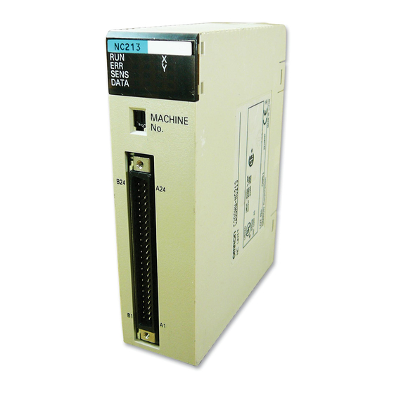
Page 34: Components
Nomenclature C200HW-NC413 C200HW-NC213 C200HW-NC113 LED indicators Show the PCU’s operating status. Unit number setting switch X, Y axis Sets the unit number for the connector PCU. X axis connector X/Y axis connector Connects stepping Z/U axis connector motor driver or Connects stepping motor servomotor driver. - Page 35 None of the above has occurred. Orange Pulses are being output to the X axis (either forward or reverse). Flashing An error has occurred, such as incorrect cable type for the X axis or faulty data. Not lit None of the above has occurred. Orange Pulses are being output to the Y axis (either forward or reverse).
- Page 36 Components Section Any unit number within the permissible range can be set, as long as it does not overlap with the unit numbers that are set for any other Special I/O Units mounted to the same Programmable Controller. Caution Be sure to turn off the power supply before making the settings.
-
Page 37: External I/O Circuitry
Z/U axis X/Y axis X axis C20HW-NC413 C20HW-NC213 C20HW-NC113 Connector pin arrangement for X and Z axes Connector pin arrangement for Y and U axes Designation Designation Output power supply, 24 VDC Output power supply, 24 VDC Output GND, 24 VDC... -
Page 38: External I/O Circuitry
External I/O Circuitry Section Note 1. Use either the 24-V origin input signal or the 5-V origin input signal, but not both. 2. Use 24 ±10% VDC as the pulse output power supply. 3. The leakage current must be less than 1.0 mA when two-wire-type sensors are used. - Page 39 M2x8 pan-head screws (two) M2x6 pan-head screws (two) Cable holder (two) Case Connector Screw (two) The following connectors (Fujitsu 360 Jack) can be used: 1, 2, 3... 1. FCN-361J048-AU (solder-type) FCN-360C048-D (connector cover) 2. FCN-363J048 (crimp-type housing) FCN-363J-AU/S (contact) FCN-360C048-D (connector cover) 3.
-
Page 40: I/O Circuitry
Caution Connect a load of 7 to 30 mA (or 7 to 16 mA for terminals with 1.6 kΩ limit resis- tance) to the output section. If a current greater than this is used, it will cause damage to the PCU’s internal components. - Page 41 External I/O Circuitry Section Add bypass resistance for loads less than 7 mA. (Circuit example) 24 VDC power supply Driver 6 mA 1 mA 7 mA Bypass resistance...
- Page 42 680 Ω note) Origin common Note Either N.C. or N.O. can be set by the axis parameters. (Refer to 4-3 Axis Param- eters Area.) Connect a switch with a switching capacity of at least 5 mA to the 24-V origin input signal terminal.
-
Page 43: Connecting External I/O
Section Connecting External I/O This section provides motor driver connection examples. When actually con- necting a motor driver, be sure to first check the specifications of the motor driver to be used. 2-4-1 Output Connection Examples Pulses are not output when the output transistor in the pulse output section is OFF. - Page 44 12 mA A2/B2 Note In this example, the 1.6 kΩ resistors of the Position Control Unit are used to allow a 24-VDC power supply to be used with a motor driver rated at 5 VDC. When wiring your system, carefully note the current required by the motor driver...
- Page 45 1.6 kΩ A5/B5 Pulse (CW+CCW) Direction input output 7 to 30 mA 1.6 kΩ A7/B7 Direction output Pulse input 7 to 30 mA A2/B2 When voltage-level output is used, the level is L for output ON, and H for output OFF.
-
Page 46: Input Connection Examples
2-4-2 Input Connection Examples Caution If the switching capacity is too low it may cause damage to the switch. Connect a switch with a switching capacity of at least 5 mA for each input. With N.C. inputs, be sure to connect a power supply for unused terminals and turn them on. - Page 47 Connecting External I/O Section The input section has both N.O. and N.C. inputs. Either can be used depending on the axis parameter settings. For details regarding axis parameters, refer to 4-3 Axis Parameters Area. Name Connection type External interrupt input signal N.O.
-
Page 48: Connecting Origin And Positioning Completed Input Signals
The positioning completed input signal is also used as an origin search com- Input Signal pleted signal in modes 2 and 3. Adjust the setting of the servomotor driver so that this signal always turns off while the servomotor is operating, and on when the motor is stopped. -
Page 49: Wiring Precautions
Solenoid Surge absorber Note Connect the diode and surge absorber as close as possible to the relay. Use a diode capable of withstanding a voltage five times higher than the circuit voltage. • Insert a noise filter into the power supply inlet if noise enters the power line (e.g., when it is connected to the same power supply as an electric welder or an... -
Page 50: Connections In Each Operating Mode
Section Connections in Each Operating Mode This section provides examples of wiring the X and Y axes. If the Y and U axes are also to be used, check the connector pin numbers in 2-3 External I/O Cir- cuitry and wire them in the same way. - Page 51 12 to 15 Search direction: CW Note “m” is the beginning DM word allocated when the unit number is set. Origin Search Operation The origin search operation is completed with the rising edge of the origin input signal after the rising edge of the origin proximity input signal.
- Page 52 Example 2: Mode 1 Connection In this example, a servomotor driver is employed and the Z-phase of the encoder is connected to the origin line driver input terminal and used as the origin input signal. An OMRON U-Series Servomotor Driver is used.
- Page 53 Connections in Each Operating Mode Section Parameter Setting Example This example is explained in terms of the X axis. For more details, refer to 4-3 Axis Parameters Area. Word Bits Setting Contents CW/CCW output 01 to 03 Limit input: N.C. contact Origin proximity: N.O.
- Page 54 Note If the positioning monitor time is set to 0, the origin search operation will wait until the positioning completed signal turns ON but other operations, such as jogging and memory operation, will ignore the positioning completed signal.
- Page 55 Connections in Each Operating Mode Section Parameter Setting Example This example is explained in terms of the X axis. For more details, refer to 4-3 Axis Parameters Area. Word Bits Setting Contents CW/CCW output 01 to 03 Limit input: N.C. contact Origin proximity: N.O.
- Page 56 OFF when the motor is operating and ON when it is stopped. Note If the positioning monitor time is set to 0, the origin search operation will wait until the positioning completed signal turns ON but other operations, such as jogging and memory operation, will ignore the positioning completed signal.
- Page 57 Connections in Each Operating Mode Section Parameter Setting Example This example is explained in terms of the X axis. For more details, refer to 4-3 Axis Parameters Area. Word Bits Setting Contents CW/CCW output 01 to 03 Limit input: N.C. contact Origin proximity: N.O.
-
Page 58: Connection Of Unused Axes
(and not the Y axis) is used. In this example, the limit input signals for both axes are set to N.C. contacts. With the C200HW-NC413, if the Z axis is used and the U axis is not used, the connection will be the same with X and Y replaced by Z and U respectively. - Page 59 Servo Relay Unit Section • The connecting cable and the type of Servo Relay Unit required will depend on the Servo Driver model connected. Refer to the tables under Connection Com- patibility given below. Connections Diagram Position Control Unit Servo Driver...
-
Page 60: Getting Started
In general, using a PCU requires the creation of ladder programs incorporating various kinds of data, status information, external input information, and so on, but here the explanations are aimed only at how to operate the motor. For details regard- ing data configuration and allocation, refer to Section 4 Data Areas. -
Page 61: Basic Operations
• Deceleration time: 100 ms (factory setting) Set the position and speed in the operating data area which is set by the com- mon parameter area. For the acceleration and deceleration times, use the fac- tory settings saved to the PCU. -
Page 62: System Configuration And Wiring
For this operation, use the configuration shown in the following diagram. In this example only the motor will rotated, without using the mechanical system. For the purposes of this example, it is assumed that the CPU is mounted to the CPU Backplane and that the unit number is set to #0. - Page 63 System Configuration and Wiring Section (2) Rotary Switch Setting Use the rotary switch on the front panel of the PCU to set the unit number (i.e., the machine No.). MACHINE No. For details regarding rotary switch settings, refer to 2-2 Components.
-
Page 64: Setting Data And Starting
After making the settings, either turn on the power again or restart (by turning Restarting AR 0100 from OFF to ON and then back OFF again). This will put the data that has been set in the common parameters into effect. - Page 65 Setting Data and Starting Section The operating memory area is the area that is automatically specified when the PCU’s unit number is set (Unit #0). Direct operation is started by the RELATIVE MOVEMENT command Wd 100 (i.e., by the turning ON of bit 10004).
-
Page 66: Data Areas
SECTION 4 Data Areas This section provides information on the data areas used by the Position Control Unit. Overall Structure ............ -
Page 67: Overall Structure
1. The user can select by means of a common parameters setting whether data is to be transferred to the PCU for use, or whether the axis parameters saved at the PCU are to be used. (Refer to 4-2 Common Parameters Area.) 2. -
Page 68: Flash Memory
The contents of the PCU’s internal memory are lost when the power supply is turned off or when the PCU is restarted. By saving the contents of the internal memory to the flash memory, parameters and other data can be retained. -
Page 69: Waiting For Pcu Startup
Programmable Controller and will ignore them. The PCU’s X-axis Busy Flag remains ON until the initial processing is completed, so after the PCU has been powered up or restarted, check to make sure that this Busy Flag has turned OFF before executing a START. - Page 70 0, then the area for unit numbers 0 and 1 is allocated. 2. Be sure to set the unit numbers so that they do not overlap with the unit num- bers of other Special I/O Units.
-
Page 71: Data Areas
I+30 to I+31 Z axis I+32 to I+33 U axis Note “I” represents the beginning word address of the area designated by the com- mon parameter area. Example Common Parameter Area When the common parameter area settings are made as shown in this example, the operating data area will be allocated to DM 0100 onwards. - Page 72 01: Operate according to the axis parameters in DM words m+4 to m+99. Reserved Word m+3 Set to 0000. Axis Parameters (Data Memory) I/O Settings X axis m+4 (NC113), Y axis m+28 (NC213), Z axis m+52 and U axis m+76 (NC413) I/O settings Item Settings Output pulse selection 0: CW/CCW output;...
- Page 73 Overall Structure Section Operation Mode Selection X axis m+5 (NC113), Y axis m+29 (NC213), Z axis m+53 and U axis m+77 (NC413) 12 11 08 07 04 03 Origin search direction Origin detection method Origin search operation Operation mode Item...
- Page 74 Overall Structure Section Origin Search High Speed X axis m+8 (NC113), Y axis m+32 (NC213), Z axis m+56 and U axis m+80 (NC413) 14 13 Factor Factor: 00: x1, 01: x10, 10: x100, 11: x1,000 (pps) Origin Search Proximity Speed...
- Page 75 X axis m+19 (NC113), Y axis m+43 (NC213), Z axis m+67 and U axis m+91 (NC413) Setting Range: 0 to 9,999 (ms) (Valid when the operation mode is set to 2 or 3.) CCW Limit (Rightmost Word) X axis m+20 (NC113), Y axis m+44 (NC213), Z axis m+68 and U axis m+92...
- Page 76 (↑: Completed; ↓: Starting) Teaching completed Error Flag (1: Error; 0: No error) Busy Flag (X-axis bit is also used as Unit initial processing flag.) Data transferring (enabled only for X-axis bit) (↑: Transferring or saving; ↓: Completed) Deceleration stop execution (↑: Completed; ↓: Beginning...
- Page 77 • Number of words to be transferred • Number of words to be transferred. 00 to 15 Transfer • Transfer source word (DM or EM word at the PC) destination (DM 1000 to DM 1999 cannot be set.) address • Transfer destination address (the PCU address)
- Page 78 Feed speed = speed des. x override / 100 (Override value is referenced only when it is set to Override Enable.) 14 13 Factor Factor: 00: x1; 01: x 10; 10: x100; 11: x1,000 (Unit: pps) NC413 I+14 I+19 I+24...
- Page 79 For details regarding data transfer, refer to Section 5 Transferring and Saving Data. For details regarding positioning sequences, refer to 4-6 Positioning Sequence Details. I/O Settings X axis 0004 (NC113), Y axis 0028 (NC213), Z axis 0052 and U axis 0076 (NC413) I/O settings Item...
- Page 80 Overall Structure Section Operation Mode Selection X axis 0005 (NC113), Y axis 0029 (NC213), Z axis 0053 and U axis 0077 (NC413) 12 11 08 07 04 03 Origin search direction Origin detection method Origin search operation Operation mode Item...
- Page 81 Note When setting the origin search high speed or the origin search proximity speed with the IOWR instruction, be sure to set both of these items together. If only one of these items is set, an error (error code 8701) will be generated and the setting will not be made.
- Page 82 Section Range: 0 to 9,999 (pulses) Default Setting: 0000 Backlash Compensation Speed X axis 0013 (NC113), Y axis 0037 (NC213), Z axis 0061 and U axis 0085 (NC413) 14 13 Factor Factor: 00: x1, 01: x10, 10: x100, 11: x1,000 (pps)
- Page 83 Range: –9,999,999 to +9,999,999 (pulses) Default Setting: 1999, 9999; 0999, 9999 Reserved X axis 0024 to 0027 (NC113), Y axis 0048 to 0051 (NC213), Z axis 0072 to 0075 and U axis 0096 to 0099 (NC413) Set to 0000. Default Setting: 0000...
- Page 84 Overall Structure Section Sequence #98 X axis 1294 (NC113), Y axis 2294 (NC213), Z axis 3294 and U axis 4294 (NC413) Same as for sequence #0. Default setting: 0000, 0000, 0000 Sequence #99 X axis 1297 (NC113), Y axis 2297 (NC213), Z axis 3297 and U axis 4297 (NC413) Same as for sequence #0.
- Page 85 Overall Structure Section Position #0 (Rightmost Word) X axis 1400 (NC113), Y axis 2400 (NC213), Z axis 3400 and U axis 4400 (NC413) Position #0 (Leftmost Word) X axis 1401 (NC113), Y axis 2401 (NC213), Z axis 3401 and U axis 4401...
- Page 86 Overall Structure Section Acceleration Time #9 X axis 1618 (NC113), Y axis 2618 (NC213), Z axis 3618 and U axis 4618 (NC413) The settings are the same as for acceleration time #1. Default Setting: 0000, 0000 Reserved X axis 1620, 1621 (NC113), Y axis 2620, 2621 (NC213), Z axis 3620, 3621 and U axis 4620, 4621 (NC413) Set to 0000.
-
Page 87: Common Parameters
Common Parameters Section Zone #0, CCW Side (Rightmost Word) X axis 1660 (NC113), Y axis 2660 (NC213), Z axis 3660 and U axis 4660 (NC413) Zone #0, CCW Side (Leftmost Word) X axis 1661 (NC113), Y axis 2661 (NC213), Z axis 3661 and U axis 4661... - Page 88 PCU mounted to Remote I/O Slave Note If this setting is “00” but the PCU is actually mounted to a Slave, a Special I/O Unit error will be generated. If that occurs, correct the setting to “01” and then power the PCU up again or restart it.
-
Page 89: Axis Parameters
Set to 0000. Axis Parameters The parameters for the X, Y, Z, and U axes are set in the axis parameters area. 4-3-1 Setting the Axis Parameters The data required for controlling the Position Control Unit (PCU) is set in the axis parameters area. -
Page 90: Axis Parameters Details
Section 4-3-2 Axis Parameters Details I/O Settings X axis m+4 (NC113), Y axis m+28 (NC213), Z axis m+52 and U axis m+76 (NC413) I/O settings These settings specify the output pulse selection, the limit input signal contacts, and so on. - Page 91 CW direction CCW direction Maximum Speed X axis m+6 (NC113), Y axis m+30 (NC213), Z axis m+54 and U axis m+78 (NC413) 14 13 Factor This setting specifies the maximum speed that can be output by the PCU. If a speed designation that exceeds this setting is given during memory operation or direct operation, the axis will be operated at the maximum speed that is set here.
- Page 92 • Speed: 1 to 3,999 (Example: C100) 1,000 x 100 = 100,000 (pps) Note An error such as a speed data BCD error (error codes 1500 to 1599) will be gen- erated if the initial speed, origin search high speed, origin search proximity speed, or backlash compensation speed is set higher than the maximum speed set here.
- Page 93 This setting specifies the speed for outputting the backlash compensation. If “0” is set, then the backlash compensation will be output at 500 pps when the initial speed is less than 500 pps, or at the initial speed when the initial speed is 500 pps or more.
- Page 94 Upper Limit: +9,999,999 (pulses) Lower Limit: –9,999,999 (pulses) Reserved X axis m+24, m+27 (NC113), Y axis m+48, m+51 (NC213), Z axis m+72, m+75 and U axis m+96, m+99 (NC413) Set to 0000.
-
Page 95: Operation Modes
Stepping motor driver Mode 0 Set mode 0 when using a stepping motor driver. A sensor is connected to the origin input signal (connector pin numbers A14/A15, B14, B15). The response time for the origin input signal is 0.1 ms. (N.O. contact setting) -
Page 96: Operating Memory Area
Pro- grammable Controller’s IR area. Note If the CCW limit setting is equal to or greater than the CW limit setting in the axis parameters area, and if the software limits are disabled, the present position will... - Page 97 ON, operation will begin with the designated sequence in the Operating Memory Area. START At the rising edge (↑) when this bit turns ON, START references the sequence number enable bit and begins memory operation. INDEPENDENT At the rising edge (↑) when this bit...
- Page 98 Name Operation Operation axis axis axis axis Output NC413 Direct RELATIVE At the rising edge (↑) when this bit opera- MOVEMENT turns ON, direct operation is NC213 tion started with the designated NC113 position treated as a relative position. • If RELATIVE MOVEMENT is...
- Page 99 Origin. Override enable This bit enables or disables the override function. • When this bit is ON (i.e., when the override is enabled), the following value will be used as the speed: Feed speed = (speed designation) x override / 100 •...
- Page 100 At the rising edge (↑) when this bit turns ON, data is written by means NC213 of a data transfer. The Y, Z, and U NC113 bits are not used. Word n+1, bit 12 is used to write the data for all axes (i.e., not just the X axis).
- Page 101 STOP command is received during axis operation. If the positioning monitor time is set to 0 in mode 2 or 3, the positioning completed signal from the Servo Driver will be ignored and the Positioning Completed Flag will turn ON when the operation is continued.
-
Page 102: Operating Data Area
The operating data area is set by the common parameter area. (Refer to 4-2 Common Parameter Area). It is determined by designating the area’s classifica- tion and beginning word. Either the DM or EM area can be used for the operating data area. - Page 103 Y axis X axis For example, to start only the X axis, set these bits to “0001.” To start the X and Z axes for linear interpolation, set these bits to “0101.” Note When setting the sequence data using the SYSMAC-NCT Support Tool, more than one axis designation cannot be made for one sequence data number.
- Page 104 Positioning Sequence Details Section Sequence #1: Terminating completion (output code: 4) Sequence #2: Automatic completion (output code: 6) Sequence #3: Bank end completion (output code: 8) Sequence number Sequence no. enable START Sequence #1 Sequence #2 Speed Pulse output Sequence Seq.
- Page 105 01 to 19: Designate dwell time numbers 1 to 19. The dwell time can be set from 0.01 s to 9.99 s (unit: 0.01 s). The timing of the next start following the elapse of the dwell time differs depending on which operation mode is used.
-
Page 106: Setting Data With The Sysmac-Nct Support Tool
4-8-1 Settings Required for Unused Axes At power up or restart, the PCU checks the parameters for all axes. If illegal data is detected, an error is generated for the relevant data and all operations other than data transfer or saving are disabled. Also, if an attempt to transfer illegal data is made, an error is generated and all axes are decelerated to a stop. - Page 107 Example Maximum speed: C500 (500,000 pps) m+33 m+57 m+81 Origin search 4250 Origin search high speed: C500 (500,000 pps) proximity speed Origin search proximity speed: C010 (10,000 pps) Note The default settings are those saved in the PCU’s flash memory.
-
Page 108: Transferring And Saving Data
SECTION 5 Transferring and Saving Data The information in this section is required for operating the motor. It explains how to transfer and save parameters and data. Transferring and Saving Data .......... -
Page 109: Transferring And Saving Data
The saved data is automatically transferred from the flash memory to the Unit’s internal memory as soon as the Unit’s power is turned on or as soon as the Unit is restarted. By means of the common parameter settings, either the flash memory or the DM can be selected for the reading of axis parameters. - Page 110 • Dwell times • Zones Note When the power is turned on or when the Unit is restarted, a choice is available by using Specify Parameters in the DM area common parameters (refer to 4-2 Common Parameter Area) between sending the axis parameters automatically from the DM area to the Position Control Unit or using the axis parameters saved in the Position Control Unit.
- Page 111 1000 to 4019. When an error code is gen- erated, the data following the error is not written. Example: Position Control Unit Data transfer Not transferred: error code 1502 If an error occurs while the axis is operating, all the axes will come to a decelera- tion stop.
-
Page 112: Writing Data With The Write Data Bit
Writing Data with the WRITE DATA Bit Section • If an error is detected by the data check, the correct data should be sent again. • If the data transfer reaches completion without error, the error will have been resolved. -
Page 113: Writing Data With The Write Data Bit
(error code 8312) will be generated. 4. Any word in the DM or EM area, except for DM 1000 to DM 1999, can be specified in I+1 (transfer source word) of the Information for Writing Data settings. -
Page 114: Timing Chart For Writing Data
14) is turned from ON to OFF. If an error occurs during data transfer, the Error Flag (word n+8, bit 12) is turned ON and the error code is output to I+27 in the operating data area. Check this error code to determine the cause of the error and correct it. - Page 115 Writing Data with the WRITE DATA Bit Section Speeds to be Transferred The beginning word address for the data transfer area is to be set at DM 0500, and the other settings are as follows: Data Address (transfer DM (transfer source)
-
Page 116: Reading Data With The Read Data Bit
(error code 8321) will be generated. 3. Any word in the DM or EM area, except for DM 1000 to DM 1999, can be specified in I+5 (transfer destination word) of the data transfer area. If a word in the range DM 1000 to DM 1999 is specified, a read transfer destination word error (error code 8322) will be generated. -
Page 117: Timing Chart For Reading Data
(word n+8, bit 14) is turned from ON to OFF. If an error occurs during data trans- fer, the Error Flag (word n+8, bit 12) will be turned ON and the error code will be output to I+27 in the operating data area. Check this error code to determine the... -
Page 118: Data Reading Program Example
In this example, speeds #0 and #1 written in 5-2 Writing Data with the WRITE DATA Bit are read. The conditions to be set are the same as those for the data writing example. The beginning word of the DM area, where the read data is to be stored, is set to DM 0500. - Page 119 Set the read destination beginning address for Position Control Unit data area to “1300” (transfer source). Set the beginning word address of the DM area where the read data is to be stored to “0500” (transfer destination). READ DATA Contents of DM after read is completed.
-
Page 120: Writing Data With Iowr
• Dwell times • Zones The Position Control Unit for which IOWR is used to write data must be mounted on the Programmable Controller’s CPU Rack or an Expansion I/O Rack. Data Writing Procedure Refer to 5-4-2 Instruction Specifications and the Programmable Controller’s operation manual for details on how to set the operand for the IOWR instruction. -
Page 121: Instruction Specifications
If the Error Flag (word n+8, bit 12) is ON, an error code will be output to I+27 in the operating data area. Check this error code to deter- mine the cause of the error and correct it. -
Page 122: Precautions When Using Iowr
IOWR is an improvised instruction which transfers all data with a single instruc- tion. It increases the transfer time for the data as well as the cycle time for the ladder program. The monitoring time for the cycle time should be adjusted as required. -
Page 123: Reading Data With Iord
Reading Data with IORD Section Example of Program Work bit 23500 is used to start writing. When debugging, it is a good idea to create a ladder program that refers to the ER Flag and Error Flag (word n+8, bit12). -
Page 124: Instruction Specifications
If the Error Flag (word n+8, bit 12) is ON, an error code will be output to I+27 in the operating data area. Check this error code to deter- mine the cause of the error and correct it. -
Page 125: Precautions When Using Iord
IORD is an improvised instruction which transfers all data with a single instruc- tion. It increases the transfer time for the data as well as the cycle time for the ladder program. The monitoring time for the cycle time should be adjusted as required. -
Page 126: Creating And Transferring Data With The Support Tool
The SYSMAC-NCT Support Tool is software that runs under Windows 95 and can be used for setting all kinds of data used by a Position Control Unit as well as for monitoring the operating status of the Position Control Unit. -
Page 127: Saving Data
Note 1. Do not turn off the power or restart the Unit while data is being saved. It may cause a failure in the Position Control Unit’s internal flash memory, or cause the Unit to operate abnormally. -
Page 128: Timing Chart For Saving Data
Data cannot be saved and transferred at the same time. Attempting to do so will result in a multiple start error (error code 8000). It is also not possible to save data while pulses are being output. The following diagram is a timing chart for saving data. - Page 129 Origin return is used to return the axis to the origin from any given location. Any location can be made the origin by using the RESET PRESENT POSITION command to change the present position to 0. Refer to 9-6 Changing the Present Position for information on resetting the present position.
-
Page 130: Setting The Data For An Origin Search
1. Set the low-speed origin search at 10 kpps or below. (Origin input signal type: N.O. input: 10 kpps max.; N.C. input: 1 kpps max.) If a higher value is set, it may not be possible to stop at the origin accurately. -
Page 131: Executing Origin Search
The origin search is conducted at low speed. There is no deceleration when Proximity Input Signal stopping with the origin input signal. Origin search proximity speed Acceleration Initial speed Start Stop If the origin search proximity speed is less than or equal to the initial speed, there will be no acceleration. -
Page 132: Operation Patterns According To Origin Detection Methods
CW limit (See note.) Start Stop Start Note If a reversal is initiated by a limit signal, a stop without deceleration will occur, and acceleration will occur after reversing. 1: Takes origin signal after origin Origin proximity input proximity signal turns ON (↑). - Page 133 Start Stop Start Note If the direction of operation is reversed, the reverse will be sudden, without deceleration or acceleration. 3: Limit input signal used instead of An origin detection method error (error code 1607) is generated and settings are origin proximity input signal not possible.
- Page 134 Start Limit Stop (Error Code: 6201) Note A limit signal is input and a stop without deceleration will occur as a result. 3: Limit input signal used instead of An origin detection method error (error code 1607) is generated and settings are origin proximity input signal not possible.
- Page 135 Limit Stop (Error Code: 6200) CW limit (See note.) Start Limit Stop (Error Code: 6200) Note A limit signal is input and operation is stopped without deceleration. 2: Origin proximity input signal not Origin input signal used Origin search proximity speed...
-
Page 136: Operation Patterns According To Operation Modes
(or a limit input signal if the origin detection method is set to 3). Origin... - Page 137 Be sure that the origin proximity input signal dog is long enough (i.e., more than the decelera- tion time).
- Page 138 “0,” the signal waits until the positioning completed input signal turns ON. Therefore, if a problem exists in the positioning completed input signal wir- ing or if the servo gain is set to a large value, busy state continues without com- pleting the positioning.
- Page 139 Stops here The stop position is the same in Mode 1 and Mode 2. For an operation where the start location of the origin search is different or where the deceleration time is short, refer to the previously-described Mode 1. In Mode 3, if deceleration is not completed when the origin proximity input signal is turned ON and then turned OFF, an origin adjustment signal will be output after deceleration is completed.
- Page 140 Origin Detection Method: 3 Deceleration starts on the rising edge of the limit input signal. After the signal turns OFF, an origin adjustment command output turns ON. If the deceleration is insufficient while the limit input signal is ON, there will be an error.
-
Page 141: Operation Pattern With Origin Compensation
Movement for origin compensation Note If the speed at the time of the compensation is below the initial speed, there will be no acceleration or deceleration for the compensation pulse output. If that speed is at least equal to the initial speed, there will be acceleration and decel- eration. -
Page 142: Origin Search Timing Charts
ORIGIN SEARCH Pulse output Time Start Stop Positioning Completed Origin Stop Flag No Origin Flag Busy Flag When Not Using an Origin Proximity Input Signal Origin input signal ORIGIN SEARCH Pulse output Time Start Stop Positioning Completed Origin Stop Flag... -
Page 143: With Origin Compensation
ORIGIN SEARCH Pulse output Time Start Stop Positioning Completed Origin Stop Flag No Origin Flag Busy Flag When Not Using an Origin Proximity Input Signal Origin input signal ORIGIN SEARCH Pulse output Time Start Stop Positioning Completed Origin Stop Flag... -
Page 144: Origin Search Deceleration Stop
Section 6-3-3 Origin Search Deceleration Stop When a deceleration stop is executed during an origin search, the origin search is canceled. The following diagram shows an example of a deceleration stop during an origin search when there is an origin proximity input signal reversal. -
Page 145: Emergency Stop Of Origin Search
6-3-4 Emergency Stop of Origin Search The origin search will be interrupted if the emergency stop input signal (A20/B20) is input while the origin search is being executed. To execute the ori- gin search again, first release the pulse output prohibition. -
Page 146: Origin Return
Section Origin Return The origin return operation is used to return the axis to the origin from any posi- tion. It is executed by the rising edge of the ORIGIN RETURN command. Note Execute ORIGIN RETURN when the origin has been established. If the origin has not been established, a present position unknown error (error code 5040) will be generated. -
Page 147: Timing Chart
Origin Return Section 6-4-2 Timing Chart A timing chart for executing an origin return on the X axis looks like this: ORIGIN RETURN (word n, bit 07) Target speed Deceleration Initial speed Initial speed Pulse output Acceleration Time Start Stop at origin... -
Page 148: Direct Operation
SECTION 7 Direct Operation This section provides an outline of direct operation, details about data areas and how to set data, and sample programs. Outline .............. -
Page 149: Outline
Programmable Controller. As a result, the positions and speeds can be input from outside and processed by calculating present positions from the Position Control Unit, for example, and position control executed with the data as if it were new data. This fact allows more flexibility, and permits position control to be exercised more simply. -
Page 150: Section 7 Direct Operation
I: Beginning word address of area designated in common parameters. n:Beginning word address of work bit determined when the Position Control Unit’s unit number was set. The positions and speeds set in the operating data area by the MOV instruction are output to the Position Control Unit automatically at I/O refresh time. -
Page 151: Setting Data For Use With Direct Operation
• When the software limit has been disabled by the axis parameters (i.e., CW limit equal to or less than the CCW limit) the position will be determined by the amount of relative movement even if an absolute position is specified. (At that time, the present position is set to “0.”) -
Page 152: Operations With Direct Operation
1. Turn the ABSOLUTE MOVEMENT command from OFF to ON ( 2. Turn the RELATIVE MOVEMENT command from OFF to ON ( When Executed by Positions to the location arrived at by designating the position for the operating ABSOLUTE MOVEMENT data area as absolute. -
Page 153: Multiple Starts With Direct Operation
Note If data in the Operating Data Area is changed during direct operation, position data will become effective when the next direct operation is designated. Speed data goes into effect as soon as it is written to the Operating Data Area, unrelated to any other commands. -
Page 154: Procedures For Setting Data For Direct Operation
P4 to P3 to P0. movements are from P4 to P3’ to P0’. Note If an attempt is made to execute something else while any of the following opera- tions are in progress, a multiple start error (error code 8000) will be generated:... -
Page 155: Direct Operation Timing Charts
Speed Time Pulse output Positioning Completed (word n+8, bit 05) Busy Flag (word n+8, bit 13) Example 2: Changing absolute position to –10,000 pulses while moving to absolute position at 10,000 pulses Position designation (I+7, I+6) Speed designation (I+8) ABSOLUTE... - Page 156 Time Pulse output Positioning Completed (word n+8, bit 05) Busy Flag (word n+8, bit 13) Example 4: Changing the relative position to –10,000 pulses while moving to relative position at 10,000 pulses Position designation (I+7, I+6) Speed designation (I+8) RELATIVE...
-
Page 157: Sample Program
7-6-1 Details of Operation The X axis is moved by relative movement at a speed of 15,000 pps to the posi- tion at 135,000 pulses. The speed is not modified by override. Position 135,000 pulses... - Page 158 Sample Program Section 7-6-3 Sample Program For details on the operating data area, refer to 4-5 Operating Data Area. Data Configuration and Operating Data Area Set by the Program Name Configuration Contents Position 0506 5000 0507 0013 Sign 0: Plus 1: Minus Set range is from –9999999 through +9999999...
-
Page 159: Memory Operation
SECTION 8 Memory Operation This section provides an outline of memory operation, details about data areas and how to set data, and sample programs. Outline .............. -
Page 160: Outline
Deceleration time #9 The positioning sequences are sent in advance by data transfer to the Position Control Unit. After the sequence numbers to be used have been set in the oper- ating memory area, the Sequence Number Enable is switched ON. -
Page 161: Axis Designation
The positions used are those for the axes designated by the axis designation. For data other than position data, the data of the started axis is used as the data to be designated in the sequence data. -
Page 162: Section 8 Memory Operation
(leftmost) NC113 Note The Error Flag (bit 12) is input to the active axis or the operating axis depending on the type of error that has been generated. In the following example, the Y axis has been specified by the axis designation when starting from the X axis. -
Page 163: Outline
• A multiple start error (error code 8000) will occur if the active axis and the axis for which start has been executed are the same axis, but the axes designated in the respective positioning sequences are different. -
Page 164: Setting Data For Use In Memory Operation
00 to 15 Setting range: 0 to 250,000 (ms) m+18 m+42 m+66 m+90 Note The speed data specified by the initial speed number in the sequence data is used as the initial speed for memory operation. -
Page 165: Operations With Memory Operation
(error code 5040) will be generated if the origin has not been established. 2. If the software limit for axis parameters is disabled (CW limit equal to or less than CCW limit), and if the designation is made while the origin is estab- lished (No Origin Flag OFF), positioning will be carried out by a relative amount, even with absolute position data. - Page 166 With automatic completion, the position with the same number as this position- (Code 1) ing sequence is executed and positioning is paused for the duration of the dwell time. Then the position with the same number as the next (+1) positioning sequence is executed.
- Page 167 (n+1) is executed. Even if the completion code is continuous, operations can be executed in which the positioning direction is reversed. In that event, the positioning will be as fol- lows regardless of the target speeds, absolute positions, or relative positions for...
- Page 168 The present position can be calculated even during continuous output. The direction of the pulse output is set by the sign for the posi- tion data of the same number. To stop this output, execute the STOP command.
-
Page 169: Linear Interpolation
The present position can be calculated even during (Codes 5 and 6) continuous output. The direction of the pulse output is set by the sign for the posi- tion data of the same number. When an interrupt signal is input, positioning is carried out according to the position data that is set. -
Page 170: Using Continuous Completion With Linear Interpolation
(completion code 2) is used. As a result, the motor may not be able to follow the variations in the pulses and may malfunction. - Page 171 When this operation is executed, therefore, set the completion code to automatic (completion code 1). The following example shows the linear interpolation of the X and Y axes starting at the X axis. At point “A” the direction of movement at the Y axis is reversed. Y axis θ...
-
Page 172: Procedures For Setting Data For Memory Operation
Timing Chart for Memory Operation Section the pulse output temporarily stops at point “A” as shown below. The stop time is approximately 8 ms. Interpolation speed Completion code: Continuous Time X axis speed acos θ bsin θ Temporary pulse stop: Approx. 8 ms Y axis speed asin θ... - Page 173 Sequence number (word I+26, bit 00 to 07) Note If the INDEPENDENT START Bit is turned from OFF to ON while the Sequence Number Enable Bit is OFF following a powerup or a restart, the sequence num- ber error (error code 8101) will be generated.
- Page 174 Sequence number (word I+26, bit 00 to 07) Note If START is turned from OFF to ON when the Sequence Number Enable Bit is OFF after a power-up or a restart, the sequence number error (error code 8101) will be generated.
-
Page 175: Sample Program
Sample Program Section Sample Program This section provides a sample program for starting the X axis. The Position Control Unit used is a C200HW-NC113. 8-6-1 Operation Positioning is executed as shown in the following diagram. Speed Target speed: 4,000 pps... -
Page 176: Setting Data
Apart from the settings given below, the factory settings should be used. When settings other than the factory settings are used, operations may vary from those shown. Refer to Section 5 Transferring and Saving Data for information on how to write data to the Position Control Unit. Positioning Sequences... -
Page 177: Program Example
Sample Program Section 8-6-4 Program Example Start switch Setting for sequence #10 Work bit Busy Flag Sequence number enable START... -
Page 178: Other Operations
SECTION 9 Other Operations This section describes the following operations: jogging, teaching, interrupt feeding, forced interrupt, deceleration stop, changing the present position, override, releasing pulse output prohibition, error counter reset output/origin-adjustment com- mand output, and backlash compensation. Jogging .............. -
Page 179: Jogging
2. Designate the start direction in the operating memory area. 3. Turn ON the JOG Bit. If the initial speed is set in the parameters, it will be in effect. 9-1-3 Operating Memory Area Allocation and Operating Data Area... -
Page 180: Teaching
Teaching Section 9-1-4 Timing Chart The following is an example of a timing chart for a JOG operation on the X axis. Directional speed (word n, bit 10) (word n, bit 09) Target speed Speed Acceleration Deceleration Initial speed Pulse output... -
Page 181: Timing Chart
Teaching address Designate a position from #00 to #99 (BCD). 9-2-4 Timing Chart The following timing chart shows an example of teaching on the X axis, taking the present position as position #2. Teaching address (word I+10, bit 00 to 07) -
Page 182: Interrupt Feeding
(movement by a specified amount) Note There will be no acceleration or deceleration if there is a reversal as a result of an interrupt input signal for a movement opposite to the direction of travel. 9-3-2 Procedure for Starting from Memory Operation... -
Page 183: Operating Memory Area Allocation And Operating Data Area Settings
Interrupt Feeding Section 2. Set the direction of the speed control with the direction designation, and then turn the Interrupt Feeding Bit from OFF to ON. 3. When the external interrupt signal is input, interrupt feeding will be executed. 9-3-4 Operating Memory Area Allocation and Operating Data Area... -
Page 184: Forced Interrupt
Section 9-3-5 Timing Chart The following timing chart illustrates interrupt feeding under direct operation, using the X axis as an example. There is a movement of 10,000 pulses in the direction of travel. Position (Interrupt feeding in the direction of travel) -
Page 185: Timing Chart
X axis as an example. Sequence #10 and Sequence #20: Continuous Sequence #11 and Sequence #21: Bank end The example shows how to execute a forced interrupt for sequence #20 while sequences #10 to #11 are being executed. Sequence number... -
Page 186: Deceleration Stop
The STOP command brings an active axis to a decelerated stop. 9-5-1 Outline of Operation The deceleration stop operation is executed when the STOP Bit is turned ON. When a deceleration stop is executed during memory operation, the stop occurs with the deceleration time set for the positioning sequence. - Page 187 A deceleration stop with linear interpolation is executed by the Deceleration Linear Interpolation Stop Bit of the axis where the Memory Operation Start Bit is turned ON. Actual deceleration starts when the Deceleration Stop Execution Bit is turned ON. The Deceleration Stop Bits of other axes become disabled and their Deceleration Stop Execution Bits remain unchanged.
- Page 188 Deceleration Stop Section When the X axis position is absolute and the Y axis position is incremental, the X axis and Y axis operate in the opposite way from that illustrated above. When the X Axis and Y Axis Positions are Both Absolute When a decelerated stop is executed before the target position has been reached, positioning is resumed for both axes by restarting.
-
Page 189: Changing The Present Position
When the PRESENT POSITION CHANGE Bit is turned ON, the present position is changed to the value set in the operating memory area, and then the origin is established. If it is changed to “0,” then that position will become the origin. -
Page 190: Override
While the Override Enable Bit is ON, the target speed is changed by applying the override value that is set in the operating data area. The override can be set from 0 to 999%. The target speeds for memory operation, direct operation, jogging, and so on, are set to 100%. -
Page 191: Releasing Pulse Output Prohibition
Pulse output can be resumed by turning OFF the emergency stop input signal and then turning ON the RELEASE PROHIBIT Bit. For the CW and CCW limit input signals, pulses can be output in the reverse direction even if the limit input signal remains ON by turning ON the RELEASE PROHIBIT Bit. - Page 192 Section Timing Chart In the following timing chart, an emergency stop input signal is turned ON during an ABSOLUTE MOVEMENT command for the X axis. In this example, it is assumed that the parameter has been set so that the origin determination will be released when the input turns ON.
-
Page 193: Error Counter Reset Output And Origin Adjustment Command Output
Can be used as general purpose output. This bit’s ON/OFF status can be output to external I/O connector (A10/A11 and B10/B11) just as it is. This bit can be always ON or OFF regardless of the Unit’s status. 1, 2 Used as error counter output. -
Page 194: Operating Memory Area Allocation And External I/O Connector Pin Arrangement
Error counter reset output or origin adjustment command output (5 v) 9-9-3 Timing Chart In the following timing chart, operation modes 0 to 2 are used, with the X axis taken as an example. Example 1: Used as general outputs in mode 0... - Page 195 Error counter reset output (PCU output signal) (A10/A11 on X axis) Sequence number (word I+26, bit 00 to 07) Example 4: Origin adjustment command output turned ON in operating mode 3 (only while pulses stopped) Origin adjustment command output (word n, bit 13)
- Page 196 In the above diagram, after positioning from the positive side, backlash is com- pensated for up to the amount of the output of pulses set for the backlash com- pensation either when positioning in the negative direction or when the position- ing direction (pulse output direction) is reversed.
-
Page 197: Backlash Compensation
9-10-4 Backlash Compensation With Linear Interpolation Backlash compensation can be set separately for each axis when two or more axes are used for interpolation operations. While backlash compensation pulses are being output, pulse outputs for all other interpolation operations are stopped. -
Page 198: Program Examples
SECTION 10 Program Examples This section provides examples of programs for using the Position Control Unit. 10-1 Operating Procedures for Program Examples ........ -
Page 199: Operating Procedures For Program Examples
10-1 Operating Procedures for Program Examples The following explanations describe some procedures for using test equipment to check the operation of the program examples introduced in this section. Refer to the various relevant sections for more information on particular procedures. - Page 200 Note When using the NC213/NC413, make the above connections as a minimum, even for unused axes. If this wiring is not done, an error will be generated for applicable axes but other axes will operate normally. Also be sure to use separate power supplies for the 24-VDC output power sup- ply and the common input power supply.
-
Page 201: Memory Operation
Section 10-2 6. Inputting the Program Refer to the program in each program example and then use tools such as the SYSMAC Support Software, Programming Console and so on to input the ladder program to the CPU Unit. 7. Checking Check the operation of each program example. -
Page 202: Section 10 Program Examples
**** Note Set the items marked in the table with asterisks (*) to their factory settings. Set the operation mode of items marked in the table with a hash mark (#) to accord with the motor and driver. Designation of the Operating Data Area The operating data area is allocated to DM 0500 through DM 0533 according to the data memory settings. - Page 203 Deceleration Times this data area needs to be set completely to the factory settings. Dwell Times Dwell times are not used in these programs, so this data area needs to be set completely to the factory settings. Zones Zones are not used in these programs, so this data area needs to be set com-...
- Page 204 Memory Operation Section 10-2 Program Operation start switch Takes the rising edge of the operation start switch. Operation checking switch Takes the status of the operation start switch. Sets #0 for the sequence number. Busy Flag Executed only when starting the first...
-
Page 205: Repeat Operation
X axis 1, 2, 3... 1. When the operation start switch is turned ON at the origin, the program out- puts 1,000 pulses CW on the X axis and stops. (Independent) (First, set the origin to “0” either by performing an origin search or by execut- ing PRESENT POSITION CHANGE.) - Page 206 **** Note Set the items marked in the table with asterisks (*) to their factory settings. Set the operation mode of those items marked in the table with a hash mark (#) to accord with the motor and driver. Designation of the Operating Data Area The operating data area is allocated to DM 0500 through DM 0533 by the data memory settings.
- Page 207 Memory Operation Section 10-2 Data Settings Axis Parameters The values for DM 1004 onwards are transferred when the power in turned on (or at restart). Positioning Sequences Address Setting Contents of settings Sequence #0 X axis designation 1000 1000 Completion code: terminating...
- Page 208 0000 Note Addresses other than the above should be set to their factory values. Dwell Times Dwell times are not used in these programs, so this data area needs to be set completely to the factory settings. Zones Zones are not used in these programs, so this data area needs to be set com-...
-
Page 209: Cancelling Positioning
START 10-2-3 Cancelling Positioning Overview • A forced interrupt can be used during memory operation to cancel the current positioning and perform a circumvention in case of an emergency. • This operation forcibly cancels the current positioning operation and executes positioning from the designated sequence number. - Page 210 X axis 1, 2, 3... 1. When the operation start switch is turned ON at the origin, the program out- puts 1,000 pulses CW on the X axis and stops. (Independent) (First, set the origin to “0” either by performing an origin search operation or by executing PRESENT POSITION CHANGE.)
- Page 211 **** Note Set the items marked in the table with asterisks (*) to their factory settings. Set the operation mode of those items marked in the table with a hash mark (#) to accord with the motor and driver. Designation of the Operating Data Area The operating data area is allocated to DM 0500 through DM 0533 by the data memory settings.
- Page 212 Acceleration time #1 Deceleration time #1 Deceleration time #1 1017 0400 Initial speed #4 Target speed #0 Note Addresses other than the above should be set to their factory values. Speeds Address Setting Contents of setting 1300 0150 Speed #0...
- Page 213 0000 Note Addresses other than the above should be set to their factory values. Dwell Times Dwell times are not used in these programs, so this data area needs to be set completely to the factory settings. Zones Zones are not used in these programs, so this data area needs to be set com-...
- Page 214 Memory Operation Section 10-2 Program Operation start switch Takes the rising edge of the operation start switch. Forced No Origin Flag interrupt switch Takes the rising edge of the forced interrupt switch. No Origin Flag Sets #0 for the sequence number.
-
Page 215: Direct Operation
2. Subsequently, as the switch turns ON each time, positioning is executed to 3000 in the CW direction on the X axis and then to 4500 in the CW direction on the X axis, and then returns to the origin and stops. (First, set the origin to “0”... - Page 216 **** Note Set the items marked in the table with asterisks (*) to their factory settings. Set the operation mode of those items marked in the table with a hash mark (#) to accord with the motor and driver. Designation of the Operating Data Area The operating data area is allocated to DM 0500 through DM 0533 by the data memory settings.
- Page 217 Direct Operation Section 10-3 DM Area DM 0000 through DM 0019 are used in this program example, and the following positions are set in this area. Setting Contents of setting Setting Contents of setting 0000 1500 CW direction, 1,500 pulses...
-
Page 218: Inching
1027 **** Note Set the items marked in the table with asterisks (*) to their factory settings. Set the operation mode of those items marked in the table with a hash mark (#) to accord with the motor and driver. - Page 219 The values for DM 1004 onwards are transferred when the power in turned on (or at restart). Positioning Sequences This data area is not used with direct operation. It should be left entirely at the factory settings. Speeds This data area is not used with direct operation. It should be left entirely at the factory settings.
-
Page 220: Linear Interpolation
(X,Y) = (5000, 1000) → (0, 2000) → (5000, 3000) → (0, 4000) → (5000, 5000) → (5000, 0) → (0, 0) The interpolation speed at this time is 500 pps. - Page 221 **** Note Set the items marked in the table with asterisks (*) to their factory settings. Set the operation mode of those items marked in the table with a hash mark (#) to accord with the motor and driver. Designation of the Operating Data Area The operating data area is allocated to DM 0500 through DM 0533 by the data memory settings.
- Page 222 Linear Interpolation Section 10-4 Data Settings Axis Parameters The values for DM 1004 onwards are transferred when the power is turned on (or at restart). Positioning Sequences Address Setting Contents of setting Sequence #0 X, Y axis designation 1000 3001...
- Page 223 Deceleration Times Make sure the data in this area is all set to the factory settings. Dwell Times Dwell times are not used in these programs, so this data area needs to be set completely to the factory settings. Zones Zones are not used in these programs, so this data area needs to be set com- pletely to the factory settings.
-
Page 224: Linear Interpolation
Linear Interpolation Section 10-4 Program Operation start switch Takes the rising edge of the operation start switch. Sets #0 for the sequence number. Busy Flag No Origin Flag Only executed when starting the first time. Sequence Enables the number enable sequence number. -
Page 225: Origin Search
• An origin search can be carried out in single-direction mode using the CW/ CCW limit input signal as an origin proximity input signal. • The origin is established by the first origin input signal after the CW or CCW limit input switch is turned from ON to OFF. - Page 226 10-5 Note Set the items marked in the table with asterisks (*) to their factory settings. Set the operation mode of those items marked in the table with a hash mark (#) to accord with the motor and driver. Designation of the Operating Data Area The operating data area is allocated to DM 0500 through DM 0533 by the data memory settings.
-
Page 227: Override
• The target speed is determined by the override coefficient set in the operating data area. • In order to use the actual target speed that has been set, either disable the override or set it to 100%. Operation Example The following is an example of changing the speed with override during continu- ous operation. - Page 228 **** Note Set the items marked in the table with asterisks (*) to their factory settings. Set the operation mode of those items marked in the table with a hash mark (#) to accord with the motor and driver. Designation of the Operating Data Area The operating data area is allocated to DM 0500 through DM 0533 by the data memory settings.
- Page 229 Override Section 10-6 Program Operation start switch Takes the operation start switch. 03005 Speed: 300 pps Busy Flag Deceleration time: JOG starts parameter Acceleration time: parameter JOG direction JOG instruction Speed change switch 1 Speed change Takes the rising switch 2...
-
Page 230: Transferring And Saving Data
• This operation can also be used for reading data from a Unit to which data has already been transferred, and for backing the data up or copying it to another Position Control Unit. - Page 231 • Zones Transfer the data needed for the operation beforehand to the Position Control Unit for both the X and Y axes, and save it in the flash memory. WRITE DATA and SAVE The data in DM 3000 through DM 3694 is transferred to the Position Control Unit,...
- Page 232 Transferring and Saving Data Section 10-7 Program READ DATA Operation start switch Takes the rising edge of the operation start switch. Data Timing Transferring determination for data reading completion Reading of axis parameters 03100 Error Error Flag determination for data reading...
- Page 233 Transferring and Saving Data Section 10-7 Setting of operating data area for reading data. READ DATA...
- Page 234 Transferring and Saving Data Section 10-7 WRITE DATA and SAVE DATA Operation start switch Takes the rising edge of the operation start switch. Data Transferring Timing determination for data writing completion Writing of axis parameters 03100 Error Error Flag determination for...
- Page 235 Transferring and Saving Data Section 10-7 Setting of operating data area for writing axis parameters Setting of operating data area for writing data. WRITE DATA SAVE DATA...
-
Page 236: Troubleshooting
SECTION 11 Troubleshooting This section describes how to diagnose and correct errors that can occur during operation. 11-1 Introduction ............. -
Page 237: Introduction
An error check is also performed when a software limit, emergency stop, or limit signal is detected. Refer to the tables in 11-4 Error Code Lists for details on the Unit operation when an error has occurred. If an emergency stop or limit signal error is detected when an error has occurred, an emergency stop or limit signal error will be output. - Page 238 Troubleshooting Flowcharts Error type Flowchart Reference Startup error See 11-4-1 Data Check at Startup. Power ON Hardware check Did an error occur? Common parame- Common parame- ters check Did an error occur? Flash memory check Did an error occur? Axis parameters...
-
Page 239: Led Error Indicators
11-2 11-2 LED Error Indicators The status of the LED indicators on the front of the Position Control Unit can be used to diagnose errors as shown in the following table. The status of the indica- tors is as follows:... -
Page 240: Reading Error Codes
11-3 Reading Error Codes When an error has occurred, an error flag will be turned on in the operating memory area and the error code will be input in the operating data area. Check this code before proceeding with error processing. -
Page 241: Error Code Lists
Error Code Lists Section 11-4 11-4 Error Code Lists 11-4-1 Data Check at Startup The following table shows the errors checked when power is turned on. Group Name Code Cause Remedy Data In this condition, only the data Parameters 0001... - Page 242 Code Cause Remedy In this condition, only the data Acceleration/ Positioning 1332 There is a BCD error in the axis transfer and data save operations deceleration monitor time parameter’s positioning monitor can be performed. All of the axes’ data time.
- Page 243 Error Code Lists Section 11-4 Note Only the SYSMAC-NCT Units can recognize error codes 0001, 0002, 0010, 0011, 0012, and 0013.
-
Page 244: Command Execution Check
Acceleration 1311 These codes indicate that acceleration time error times 1 to 9 have a BCD error or the All operating 1319 setting is out-of-range (0 to 250 s). axes will be axes will be Deceleration... - Page 245 Dwell time BCD 4001 These codes indicate that dwell times 1 error to 19 have a BCD error or the setting is 4019 out-of-range (0 to 9.99 s). (The last two digits of the code indicate the dwell time number where the error...
- Page 246 Other operating executing axes won’t be RELEASE affected. PROHIBIT. CW limit stop 6100 The axis was stopped by a CW Move in the CCW limit input signal. direction after executing RELEASE PROHIBIT. CCW limit stop 6101 The axis was stopped by a CCW Move in the CW limit input signal.
- Page 247 Code Cause Clearing method Operation after error Origin search No origin 6200 The Unit is set for a proximity Perform the origin Other operating proximity input input signal, but no origin search again after axes won’t be signal proximity input signal was checking the origin affected.
- Page 248 The origin return speed is 0 or error there is a BCD error. Present Present position 7400 There is a BCD error in the position error position data. JOG speed 7500 The JOG speed is 0 or there is a error BCD error.
- Page 249 A START or INDEPENDENT Make sure you The current START command was executed aren’t specifying a command will be for a different axis, but a busy axis busy axis and ignored and other was specified in the axis execute the operating axes specification.
- Page 250 Execute the Write transfer: 8310 The number of words to transfer affected. command again number of was set to 0, had a BCD error, or after changing the words error exceeded the maximum. incorrect setting. Write transfer: 8311 There was a BCD error or...
- Page 251 9300 An attempt was made to save Execute the data The current memory error data to flash memory, but the data save operation instruction won’t couldn’t be saved because of a again. The error be executed. problem with the flash memory.
-
Page 252: Cpu Error Indicators
11-5 CPU Error Indicators The CPU Unit of the C200H/HS and C200HX/HG/HE PCs has the following indi- cators to show errors that occur in the Position Control Unit. The errors are indi- cated for the Position Control Unit as a Special I/O Unit. -
Page 253: Useful Flags And Control Bits
To restart a Special I/O Unit, toggle (OFF → ON → OFF) the corresponding Special I/O Unit Restart Bits Restart Bit shown in the following table. These bits can be used to restart the Unit without turning off the power supply. Bit address... -
Page 254: A Data Calculation Standards
Note An additional error of ±0.02% max. occurs in the actual speed. Power Up Time When the Position Control Unit is powered up or restarted, the time required for the Unit to complete its initial pro- cessing and be ready to recognize the START command is approximately 800 ms. - Page 255 Data Transfer and Data Saving Time When data is transferred using either the READ DATA and WRITE DATA commands (word n+1, bits 12 and 13) or the IORD and IOWR instructions, the execution time will vary depending on the number of words of data to be transferred.
- Page 256 Data Transferring Flag = (25506) Bit The average time required for saving data is approximately three seconds, but it may take as long as 33 seconds in some cases. If the time required for saving data exceeds 33 seconds, however, a flash memory error (error code: 9300) will occur and the data save will be interrupted.
- Page 257 Sequence n External Interrupt Processing Time The response time is as shown below with respect to external inputs such as limit sensors and interrupt inputs. The Position Control Unit continues the current operation during the response time for each external input.
- Page 258 The target speed can be changed during direct operation by changing the speed data set in the operating data area. The time from when the speed is changed until the change is reflected in the pulse output is as follows:...
-
Page 259: B Estimating Times And Pulses For Acceleration/Deceleration
Accordingly, the time it takes to reach the target speed, the time from the target speed to the initial speed, as well as the number of pulses for each of them, can all be found by means of the formulas shown below. - Page 260 Estimating Times and Pulses for Acceleration/Deceleration Appendix B Example In this example, numeric settings are entered for the operation pattern shown below. Speed (pps) 35000 30000 5000 Time (ms) Maximum speed setting: = 35,000 pps Acceleration time setting: = 400 ms...
-
Page 261: C Error Code List
Appendix C Error Code List This table is for the C200HW-NC413. For C200HW-NC113 or C200HW-NC113 PCUs, refer to Section 4 Data Areas and check the words and addresses. Error code Error name Related data 0001/0002 Parameters destruction, data Flash memory... - Page 262 Zone 2 CCW error Address: 1668, 1669/2668, 2669/3668, 3669/4668, 4669 2000 to 2099 Target position BCD error Address: 1400 to 1599/2400 to 2599/3400 to 3599/4400 to 4599 3000 to 3099 Sequence data error Address: 1000 to 1299/2000 to 2299/3000 to 3299/4000 to 4299...
- Page 263 Read transfer: destination word error 8400 Error counter reset/ origin adjustment output error 8500 Override error I+9/I+14/I+19/I+24 8600 Positioning timer timeout Servomotor driver positioning completed input signal, m+19/m+43/m+67/m+91 (address: 0019/0043/0067/0091) 8700 IORD format error 8701 IOWR format error 9300 Flash memory error...
- Page 264 Appendix D Effect of Cable Length on Pulse Output Depending on the cable used for connecting the Position Control Unit and a load (such as a servomotor driver), there may be effects on waveform distortion, pulse width, and so on.
-
Page 265: E Parameter Coding Sheets
Customer name: Machine name: Prepared by: Common Parameters Function Designation of operating data area Beginning word of operating data area See Unit Mounting Position; Unit mounting position; parameter designation Parameter Designation below. Reserved Unit Mounting Position; Function Parameter Designation... - Page 266 Axis Parameters X axis Y axis Z axis U axis Function I/O setting See I/O Setting on the next page. See Operation Mode Operation mode selection Selection on the next page. Maximum speed Initial speed Origin search high speed Origin search proximity speed...
- Page 267 1: Pulse direction output 01 to 03 Reserved Set to 0. Limit input signal type 0: N.C. contact; 1: N.O. contact Origin proximity input signal type 0: N.C. contact; 1: N.O. contact Origin input signal type 0: N.C. contact; 1: N.O. contact...
- Page 268 1 (Mode 1): Uses servomotor driver, and uses encoder’s Z-phase signal for origin input signal. Does not use positioning completed input signal. 2 (Mode 2): Same as Mode 1, but uses positioning completed input signal. 3 (Mode 3): Uses OMRON H-Series or M-Series Servomotor Driver.
-
Page 269: F Using With Cs1-Series Pcs
Observe the following points when using C200HW-NC113/NC213/NC413 PCUs with CS1-series PCs. Differences in Operating Memory Area and Common Parameter Area Allocations The beginning words of the operating memory area (n) and common parameter area (m) will differ in the way shown below. - Page 270 Data Transfer Area (k onwards) The data transfer area (set using operating data area words I to I+5) must be within the following ranges. The data transfer area is determined by the transfer source word or transfer destination word along with the number of trans- fer words.
- Page 271 DM area. These settings are required for both direct operation and memory operation. 2. Make the operating data area settings in words I to I+33 of the DM or EM area (designated with the common parameters). These settings are required for both direct operation and memory operation.
- Page 272 MENT Bit (X axis: word n, bit 04) from OFF to ON. To start memory operation, turn the Sequence Number Enable Bit (X axis: word n, bit 00) and the START Bit (X axis: word n, bit 01) or the INDEPENDENT START Bit (X axis:...
- Page 273 Using with CS1-series PCs Appendix F Programming Direct Operation The following program example transfers position data already set in the DM area in order. Operation start switch Turns a ON for one cycle when DIFU(013) the operation turns ON. 200213...
- Page 274 D(X+18) D(X+19) Note If the START Bit or INDEPENDENT START Bit is turned from OFF to ON immediately after power up or restart, with the Sequence Number Enable Bit turned OFF, a sequence number error (error code 8101) will be generated.
- Page 275 A sample program is provided below for writing the indicated speed data to the Position Control Unit. The begin- ning word address of the transfer data is to be D00500, and the other settings are as indicated. The data will be transferred to the Position Control Unit designated as unit number 2.
-
Page 276: Index
1, 39, 40 acceleration time number, 92 examples in mode 2, 41, 42 examples in mode 3, 43, 44 acceleration times #1 through #9, setting, 72 RELATIVE MOVEMENT, 51 acceleration/deceleration curve, setting, 61, 69, 80 common parameter area, example settings, 51... - Page 277 CPU error indicators, 243 data checking, 98 external interrupt processing time, 248 reading with IORD, 110 reading with the Read Data bit, 103 saving, 96, 114 time required to read data, 246 time required to write data, 247 features, 2...
- Page 278 160 origin proximity signal type, 66, 77 low-speed origin search, setting, 68, 79 origin return, 134 origin search low speed. See low-speed origin search origin search basic explanation, 8 origin search proximity speed, setting, 61 data settings, 118...
- Page 279 8 for speed change, 249 for target position change, 249 teaching operation, explanation, 171 Restart Bits, Special I/O Unit Restart Bits, 244 terminals, with and without resistance, 27 rotary encoders, 11 terminating completion, in memory operation, 156...
- Page 280 Index writing data example program, 103, 109 time required, 247 wiring with IOWR, 107 basic wiring for stepping motors, 50 with Write Data bit, 100 error counter reset, 33 zones, basic explanation, 9 I/O circuit diagrams, 27 precautions, 36–46 zones #1 through #2, setting, 74...
-
Page 281: Revision History
Revision History A manual revision code appears as a suffix to the catalog number on the front cover of the manual. Cat. No. W334-E1-04 Revision code The following table outlines the changes made to the manual during each revision. Page numbers refer to the previous version. - Page 282 The following changes and corrections were made. Page xiv: Precaution added. Page xv: Information in warning changed. Pages 41, 43, 151, 154, 156, 157, and 159: Note added. Page 46: Models added. Page 88: Information added for bit 05. Page 89: Information added for bit 15.
- Page 283 Regional Headquarters OMRON EUROPE B.V. Wegalaan 67-69, NL-2132 JD Hoofddorp The Netherlands Tel: (31)2356-81-300/Fax: (31)2356-81-388 OMRON ELECTRONICS LLC 1 East Commerce Drive, Schaumburg, IL 60173 U.S.A. Tel: (1)847-843-7900/Fax: (1)847-843-8568 OMRON ASIA PACIFIC PTE. LTD. 83 Clemenceau Avenue, #11-01, UE Square,...
- Page 284 Authorized Distributor: Cat. No. W334-E1-04 Note: Specifications subject to change without notice. Printed in Japan...
Need help?
Do you have a question about the C200HW and is the answer not in the manual?
Questions and answers