
Related Manuals for Omron SYSMAC C200H-TC


Summary of Contents for Omron SYSMAC C200H-TC
- Page 1 Cat. No. W225-E1-3 SYSMAC C200H-TC Temperature Control Units Downloaded from Elcodis.com electronic components distributor...
- Page 2 C200H-TC Temperature Control Units Operation Manual Revised March 2000 Downloaded from Elcodis.com electronic components distributor...
- Page 3 Downloaded from Elcodis.com electronic components distributor...
- Page 4 OMRON. No patent liability is assumed with respect to the use of the information contained herein. Moreover, because OMRON is constantly striving to improve its high-quality products, the information contained in this manual is subject to change without notice.
- Page 5 Downloaded from Elcodis.com electronic components distributor...
-
Page 6: Table Of Contents
TABLE OF CONTENTS PRECAUTIONS ....... . . 1 Intended Audience ............2 General Precautions . - Page 7 About this Manual: This manual describes the installation and operation of the C200H-TC Temperature Control Units and includes the sections described below. Also briefly described is the basic operation and installation of the C200H-DSC01 Data Setting Console. Please read this manual carefully and be sure you understand the information provided before attempting to install and operate a Temperature Control Unit or Data Setting Console.
- Page 8 PRECAUTIONS This section provides general precautions for using C200H Temperature Control Units and related devices. The information contained in this section is important for the safe and reliable application of the C200H Temperature Control Units. You must read this section and understand the information contained before attempting to set up or operate a C200H Temperature Control Unit.
-
Page 9: Intended Audience
It is extremely important that a PC and all PC Units be used for the specified purpose and under the specified conditions, especially in applications that can directly or indirectly affect human life. You must consult with your OMRON representative before applying a PC system to the above-mentioned applications. -
Page 10: Operating Environment Precautions
Application Precautions Operating Environment Precautions Caution Do not operate the control system in the following locations: Locations subject to direct sunlight. Locations subject to temperatures or humidity outside the range specified in the specifications. Locations subject to condensation as the result of severe changes in tempera- ture. - Page 11 Application Precautions Always use the power supply voltages specified in this manual. An incorrect voltage may result in malfunction or burning. Take appropriate measures to ensure that the specified power with the rated voltage and frequency is supplied. Be particularly careful in places where the power supply is unstable.
-
Page 12: System Configuration And Features
SECTION 1 System Configuration and Features This section describes Temperature Control Unit features and describes its basic system configuration. Features ..............Basic System Configuration . -
Page 13: Features
Section 1-1 Features Features The Temperature Control Unit measures the temperature of an object with a connected temperature sensor (thermocouple or platinum resistance thermom- eter) and controls the temperature according to a preset control mode. PID with Feed-forward Circuitry (Feed-forward PID) Stable temperature control is achieved using PID control with feed-forward cir- cuitry and an auto-tuning feature. -
Page 14: Basic System Configuration
Basic System Configuration Section 1-2 Basic System Configuration C200H/C200HS, C200HX/HG/HE, CS1 PC Temperature Control Unit: C200H-TC00 (for thermocouples) C200H-TC10 (for platinum resistance thermometers) Connecting cables: C200H-CN225 (2 m) C200H-CN425 (4 m) Data Setting Console C200H-DSC01 Recommended cable: ES1000-CA021- (1/2 m) 24 VDC Loop 1 Loop 2... - Page 15 Basic System Configuration Section 1-2 Applicable CPU Units PC Series CPU Unit Mounting restrictions CS1H-CPU None CS1G-CPU C200HX/HG/HE C200HE-CPU11/32/42-E/ZE None C200HG-CPU33/43-E/ZE C200HX-CPU34/44-E/ZE C200HG-CPU53/63-E/ZE None C200HX-CPU54/64-E/ZE C200HX-CPU65-ZE/85-ZE C200HS C200HS-CPU01-E/01-EC/21-E/21-EC/31-E/03-E/ None 23-E/33-E C200H C200H-CPU01-E/03-E/11-E/21-E/23-E/31-E Cannot be mounted to the two rightmost slots on the CPU Rack.
- Page 16 Basic System Configuration Section 1-2 If the C200H Slave Rack is connected to another SYSMAC model Remote I/O Master Unit, such as the C500, C1000H, or C2000H, it is not possible to use a Special I/O Unit with the C200H Slave Rack. WARNING Always turn the PC power OFF before connecting or disconnecting a Unit, terminal block, or output connector.
- Page 17 Basic System Configuration Section 1-2 When various settings require frequent rewriting, write to RAM, verify the setting values, and then save the data by writing it to EEPROM. The data written to the RAM will be deleted when the power is turned OFF. The following commands can be used to write to RAM.
-
Page 18: Connections And Settings
SECTION 2 Connections and Settings This section provides information on the connections and settings of the Temperature Control Unit. Nomenclature ............Switch Settings . -
Page 19: Nomenclature
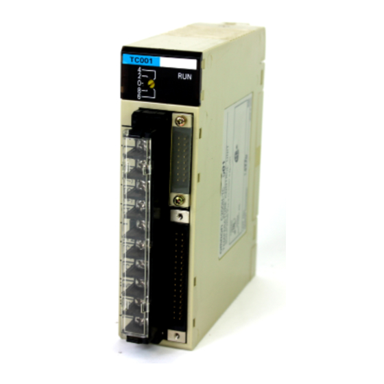
Section 2-1 Nomenclature Nomenclature C200H-TC00j (For Thermocouple) Front Panel Rear Panel Model label Cover RUN indicator SW202 (switching memory contents (sensor type setting) and setting direction under the cover) SW203 (Unit number setting) (operation and function settings) Data Setting Console connector Rack connector Output connector... -
Page 20: Switch Settings
Switch Settings Section 2-2 Indicators Lit when the Temperature Control Unit is operating normally. Unlit when an alarm occurs, and Unit operation stops. Switch Settings The function and setting of switches are identical for all models, except SW202. Unit Number Unit number setting The cut-out indicates the selected position. - Page 21 Switch Settings Section 2-2 The switch is factory-set to OFF: Parameters can be set from the Data Setting Console only. The new setting is valid immediately after the switch setting is changed. Removing and Attaching the Cover Removing the Cover Attaching the Cover Insert a small flat-blade screw- Place the right edge of the...
- Page 22 Switch Settings Section 2-2 C200H-TC10j Setting Sensor type The switch is factory-set to OFF. See Appendix B Sensor T emperature Measurement Range for the measurable temperature range. Operation and Function Setting SW203 Operation and Function Setting Function Not used Operation in C200H Continue control Interrupt control program mode...
-
Page 23: Wiring
Wiring Section 2-3 Control Action Reverse: For heating control with a heater. The heater output is increased when the mea- sured temperature is below the SP (i.e., a negative temperature difference). Normal: For cooling control of overheated objects using cooling water or some other method. - Page 24 Wiring Section 2-3 C200H-TC10j Platinum Resistance Thermometer CT: Current Transformer Pt: Platinum resistance thermometer Heater wire Loop 1 Refer to the table below. Loop 2 24 VDC 0.2 A The 24-VDC output from the C200H CPU or the Power Supply Units is convenient. Terminal No.
- Page 25 Wiring Section 2-3 Crimp Terminals The screws on the terminal block are M3.5 self-rising terminal screws. Use the following types of M3.5 crimp terminals. 7 mm max. 7 mm max. Soldered Lead Strip insulation from 7 to 10 mm at the end of the wire and carefully solder the lead.
- Page 26 Wiring Section 2-3 Type of thermocouple Compensating conductor Classification by Classification by Constituent materials application and application and Symbol Previous Symbol Previous + conductor – conductor tolerance tolerance symbol symbol (reference) (reference) Alloy with copper TX-G WCC-G General-purpose, Copper standard class or nickel as major constituent TX-GS...
- Page 27 Wiring Section 2-3 Circuit Diagrams C200H-TCj01 Transistor Output 24 VDC C200H-TCj02 Voltage Output OUT (+) OUT (–) C200H-TCj03 Current Output OUT (+) OUT (–) Applicable Connectors The following connector set manufactured by Fujitsu is included with the Unit: FCN-361J032-AU (soldering connector) FCN-360C032-B (cover) Connector Wiring After soldering the lead to each pin, insulate with heat-shrink tube to prevent...
- Page 28 Output Cable The output cables in the table below are recommended. Model Cable length (L) ES1000-CA021-102 ES1000-CA021-202 32-pin connector 20-pin connector (manufactured by Fujitsu) (manufactured by OMRON) FCN-361J032-AU XG4M-2030 16.1 Wiring Diagrams 32-pin connector 20-pin connector 16 16 10 10...
- Page 29 Wiring Section 2-3 Remote I/O Terminal Remote I/O Terminal in the table below is recommended for transistor output. Model Specification Relays used G7TC-OC08 Common (+) 8 x G7T-1112S (max. resistive load: 220 VAC, 2A) Note One P7TF-OS08 I/O Terminal and two G7T-1112S Relays may be purchased separately and used.
- Page 30 Wiring Section 2-3 Connection Precautions 1, 2, 3... 1. Tighten the lock screws after inserting the connector into the Unit. 2. Push the connector firmly into the Data Setting Console until the clips fully lock. 3. Power is supplied through the connecting cable from the Temperature Con- trol Unit.
-
Page 31: Data Setting Console Operation
SECTION 3 Data Setting Console Operation This section provides the basic operating procedures of the Data Setting Console including parameter settings and displays. Operating Procedure ............Data Flow . -
Page 32: Operating Procedure
Section 3-1 Operating Procedure Operating Procedure After preparing the CPU Unit, follow the procedure below to use the Tempera- ture Control Unit. 1, 2, 3... 1. Set the switches on the front and rear panels according to the operating con- ditions. -
Page 33: Data Flow
Data Flow Section 3-2 Data Flow The data flow in the Temperature Control Unit is shown in the diagram below. If SW2-2 is ON Write I/O bus Temperature CS1, Control Unit C200H-CPU Read Read Write If SW2-2 is OFF Data Setting Console The read operation and setting the executed bank number are possible from a user program or from a device, such as the Programming Console, regardless of... -
Page 34: Nomenclature And Features
Nomenclature and Features Section 3-3 Nomenclature and Features 3-3-1 Nomenclature Front View Side View Data display Operation indicators Display for Cam Positioner Cover Down Key Panel mounting bracket Up Key (With cover open) (Refer to Appendix D Dimensions for details about Display Key panel mounting.) Rear View... - Page 35 Nomenclature and Features Section 3-3 3-3-2 Features Data Display Name Function PV (Process Displays the PV or the parameter symbol selected with the Level Value) or Display Key (Refer to next page). SV (Set Value) Displays the SV or setting/monitored data corresponding to the parameter symbol selected with the Level, Display or Loop Keys and indicated in the PV display.
-
Page 36: Parameter Displays And Settings
Parameter Displays and Settings Section 3-4 Operation Keys Name Function Level Key The parameter items are divided into three display groups (Refer to display levels 0 to 2 on the next page). Press this key to switch from one group to another. The display levels automatically cycle in the sequence 0 –>... - Page 37 Parameter Displays and Settings Section 3-4 Display Parameter Display Write Read Loop Bank Data range Default value Page level symbol Control period 1 to 99 s 20 s (see note 1 and 3) Hysteresis (see 0.0 to 999.9 C 0.8 C note 2) hysa Alarm hysteresis...
- Page 38 Parameter Displays and Settings Section 3-4 3-4-2 How to Display and Set Parameter Data PV and SV (Display Level 0) Process value (monitored every 500 ms) Currently set set value. Units: C or F. The SV can be changed from this display. Valid SV Range Set the SV in the range between the SV lower limit and the SV upper limit.
- Page 39 Parameter Displays and Settings Section 3-4 Alarms SV 1 and SV 2 (Display Level 0) Alarm 1/2 parameter symbol Currently set alarm value. Units: C or F. The setting can be changed from this display. The alarm mode is set with the Alarm 1/2 Mode pa- rameter described on the following page.
- Page 40 Parameter Displays and Settings Section 3-4 Lower Limit Alarm with Standby Sequence Standby sequence cancel point Hysteresis OFF point Alarm SV Alarm output The standby sequence is restarted in the following situations. When SV is changed. When executed bank number is changed. When alarm mode is changed.
- Page 41 Parameter Displays and Settings Section 3-4 Heater Current Monitor (Display Level 1) Heater current monitor parameter symbol Currently set heater current value. Units: Amperes (A). If the current exceeds 5.5 A, a CT Input Overflow error occurs and ffff is displayed. Input Shift Value (Display Level 0) Input shift value parameter symbol Currently set input shift value.
- Page 42 Parameter Displays and Settings Section 3-4 Hysteresis is an operating band provided for ON/OFF operation to prevent out- put chattering (repeated ON/OFF switching) and eliminate noise influences. Hysteresis Hysteresis is applied in the following situations. When ON/OFF control is selected (SW203-1 is ON). When PID control with feed-forward circuitry (SW203-1 is OFF) and P (propor- tional band) is 0.
- Page 43 Parameter Displays and Settings Section 3-4 To interrupt, press the Level and Display Keys again to display at. When at appears, press the Up Key. On interrupt, the at display disappears and the pro- cess value is displayed. Auto-tuning operates only when SW203-1 on the rear panel is set to OFF to en- able PID control with feed-forward circuitry.
-
Page 44: Pc Memory Allocation And Programming
SECTION 4 PC Memory Allocation and Programming This section provides the C200H PC’s memory allocation for the Temperature Control Unit. Basic programming procedures and examples are also provided. Memory Allocation ............4-1-1 Memory Allocation Table . -
Page 45: Memory Allocation
Section 4-1 Memory Allocation Memory Allocation Memory Allocation The Temperature Control Unit is allocated 10 words in the IR or CIO Area ac- cording to the unit number switch setting on the front of the Unit. These words are used as an I/O refresh data area. The IR or CIO Area words used by the Tem- perature Control Unit are refreshed each I/O refresh scan of the CPU Unit. - Page 46 Section 4-1 Memory Allocation 4-1-1 Memory Allocation Table SW2-1 Set for Fixed Memory Allocations (CS1: n=2000+10 x Unit number) (C200HX/HG/HE, C200HS, C200H: n=100 + 10 x Unit number) Word Output Loop 1 SP (see note) Loop 2 SP (see note) Loop 1 executed bank Loop 2 executed bank Loop 1...
- Page 47 Section 4-1 Memory Allocation Word Word Input Loop 1 PV (see note) Loop 2 PV (see note) Read data Write Write Read error com- com- plete plete Loop 1 executed bank Loop 2 executed bank SW data number number Loop 1 status data Sen- STOP Con-...
- Page 48 Section 4-1 Memory Allocation Address Data item Data contents Word Outputs the Loop 1 and Loop 2 PV (process value) as 4-digit Input 15 to 00 Loop 1 PV BCD data For platinum resistance thermometer data the least BCD data. For platinum resistance thermometer data, the least 15 to 00 Loop 2 PV significant digit is 0.1.
- Page 49 Section 4-1 Memory Allocation SW2-1 Set for Normal Memory Allocations (CS1: n=2000+10 x Unit number) (C200HX/HG/HE, C200HS, C200H: n=100 + 10 x Unit number) Address Data item Data contents Word Output 15 and 14 Read/Write The data bit sets operation to read or write. Read/Write Write = 01 Read = 00 command...
- Page 50 Section 4-1 Memory Allocation Address Data item Data contents Word Input 07 to 01 Not used. Each bit is set to 0. Read Bit set to 1 when the read operation due to the commands set complete with Wd (n) ends normally. The bit is set to 0 when the command is changed.
- Page 51 Section 4-1 Memory Allocation Parameter Com- Write Read Loop Bank Actual data Write/Read Default value mand range data range Alarm SV 1 (see note 4) 0 Alarm mode TC 1, 4, 5: 0000 to 0 to 9999 C 9999 Other TCs: F999 to –999 to 9999...
- Page 52 Section 4-1 Memory Allocation 4. Does not apply when Alarm Mode = 0 5. Refer to 3-4 Parameter Displays and Settings for details of the parameters. 6. Thermocouple = TC Platinum Resistance Thermometer = Pt RAM Write Command Parameter Com- Write Read Loop...
-
Page 53: Data Flow
Programming Section 4-3 5. Data written by the RAM write command will disappear when the power is turned OFF. 6. Data cannot be read using the RAM write command. 7. Refer to 3-4 Parameter Displays and Settings for details of the parameters. Data Flow Refer to 3-2 Data Flow for the data flow in the Temperature Control Unit. - Page 54 Programming Section 4-3 Example 1: Write with SW2-1 Set for Normal Memory Allocations Description and Conditions Example The user program makes the following settings: Loop 1 SP = 200 C (Bank no. = 1) Loop 2 SP = 250 C (Bank no. = 2) Loop 1 executed bank number = 1 Loop 2 executed bank number = 2 Loop 1 heater burnout current value = 2.0 A...
- Page 55 Programming Section 4-3 Sample Program 10701 10700 SW2-2 (10701) switch ON detection DIFU (13) (C200H PC) Normal (C200H) 23200 25315 10701 10700 Program runs when operation is started or 23201 SW2-2 turned ON 1 cycle ON Normal (C200H) 23200 23201 MOV (21) #1200 #1200...
- Page 56 Programming Section 4-3 23206 DIFD (14) 23207 23205 To start next data KEEP(11) 23206 10608 Write complete 23207 #601B Heater burnout current MOV (21) value command #601B Bank number not required Bit data: 0101 Loop 2 MOV (21) Write #0025 Write data (2.5A) 23208 Write request...
- Page 57 Programming Section 4-3 Timing Chart 1 cycle 25315 (1 cycle ON) 23201 23202 23203 23204 23205 23206 23207 10200 (Write request) 10608 (Write complete) : Point of Write command execution In addition to the above, IR 23201 will turn ON for one cycle on the rising edge of SW2-2 (IR 10701).
- Page 58 Programming Section 4-3 Sample Program Insert the program below before the END instruction in the program on page 47. 25313 Read Loop 1 PV from IR103 to DM 0000. MOV (21) Read operation is not affected by SW2-1 and Normally ON SW2-2 settings.
- Page 59 Programming Section 4-3 23304 Read data from IR105 to DM 0001. MOV (21) DM0001 Execute next Read command. MOV (21) #201A Heater Current #201A Monitor command Bank number not required Bit data 0010 DIFD (14) Loop 2 23305 Read 23305 KEEP(11) 23306 Wait for Read Complete...
- Page 60 Programming Section 4-3 Timing Chart 1 cycle 23301 23302 23303 23304 23305 23306 23307 Wd 105 (Read data) 10600 (Read complete) : Point of Read command execution : Point where data (1) is read. : Point where data (2) is read. 4-3-2 CS1 Series Example with Fixed Memory Allocations Description and Conditions...
- Page 61 Programming Section 4-3 Sample Program A20011 200701 200700 MOV (021) Set #0080 for word 2000 (Loop 1 SP). 1 cycle ON CPU Unit Fixed #0080 2000 MOV (021) Set #0200 for word 2001 (Loop 2 SP). #0200 2001 Set #1300 for word 2002 (executed bank number). MOV (021) #1300 #1300...
- Page 62 Programming Section 4-3 20701 200700 SW2-2 (200701) switch ON DIFU (013) detection (CPU Unit) CPU Unit Normal 2320 A20011 200701 200700 Program runs when opera- 23201 tion is started or SW2-2 1 cycle ON CPU Unit Normal turned ON 23200 23201 MOV (021) 1200...
- Page 63 Programming Section 4-3 23203 #6200 MOV (021) SP setting instruction #6200 Bank number 2000 Bit data: 0110 Loop 2 MOV (021) Write #0250 2001 Write data (250 C) 23204 DIFD (014) 23205 To start next data 23203 KEEP(011) 23204 Write complete 200608 23205 #501B...
- Page 64 Programming Section 4-3 Timing Chart 1 cycle A20011 (1 cycle ON) 23201 23202 23203 23204 23205 23206 23207 200200 (Write request) 200608 (Write complete) : Point of Write command execution In addition to the above, CIO 23201 will turn ON for one cycle on the rising edge of SW2-2 (CIO 200701).
- Page 65 Programming Section 4-3 Sample Program Insert the program below before the END instruction in the program on page 54. CF113 Read Loop 1 PV from CIO 2003 to D0000. MOV (021) Read operation is not affected by SW2-1 and Always ON SW2-2 settings.
- Page 66 Programming Section 4-3 23304 Read data from CIO 2005 to D0001. MOV (021) 2005 D0001 Execute next Read command. MOV (021) #201A Heater Current #201A Monitor command 2000 Bank number not required Bit data 0010 DIFD (014) Loop 2 23305 Read 23305 KEEP(011)
- Page 67 Programming Section 4-3 Timing Chart 1 cycle 23301 23302 23303 23304 23305 23306 23307 Wd 2005 (Read data) 200600 (Read complete) : Point of Read command execution : Point where data (1) is read. : Point where data (2) is read. 4-3-3 Operation Timing The following descriptions apply to the C200HX/HG/HE, C200HS, C200H, and CS1 Series.
- Page 68 Programming Section 4-3 Temporarily turn the Write Request Flag OFF before executing the second and subsequent write operations. Writing is enabled on the ON rising edge of the Write Request Flag. The Loop 1 and 2 executed bank number (Wd n+2) sets data directly. The data is written to the Temperature Control Unit RAM.
- Page 69 SECTION 5 Troubleshooting This section provides possible errors and error remedies. Error Detection ..............Downloaded from Elcodis.com electronic components distributor...
-
Page 70: Error Detection
Section 5 Error Detection Error Detection When an error occurs in an input or in the Unit, details of the error are reported to the Data Setting Console and input relays. Sensor Input Errors Display Error name Output status after Cause Remedy error... - Page 71 Section 5 Error Detection The bits shown in the table below are set to 1 when a heater burnout alarm oc- curs. Wd (n+8), bit 02 Loop 1 heater burnout alarm Wd (n+9), bit 02 Loop 2 heater burnout alarm Use one of the methods below to reset a heater burnout alarm.
- Page 72 Section 5 Error Detection The connecting cable is disconnected. The connecting cable is broken. A circuit in the Data Setting Console is defective. A circuit in the Temperature Control Unit is defective. After determining the cause of the error, correct the problem or replace the Unit. Temperature Control Not Temperature control will not be performed in either one of the following cases.
- Page 73 Appendix A Specifications General Specifications Conforms to the CPU Unit specifications. Item C200H-TC00 C200H-TC10 Connectable temperature Thermocouple (R, S, K, J, T, E, B, N, L, U) Platinum resistance thermometer (JPt100, sensor (see note 1) Pt100) Current Transformer detection 0.1 to 4.9 A (with a heater burnout detecting current difference of 0.5 A min.) current Indication accuracy: 5% FS 1 digit max.
- Page 74 Appendix A Specifications Output Characteristics Open-collector Output (Pulse) C200H-TC 01 +10% External supply voltage 24 VDC –15% Max. load voltage 24 VDC max. Max. load current 100 mA max. Residual voltage when ON 3 V max. Leakage current when OFF 0.3 mA max.
- Page 75 Appendix B Sensor Temperature Measurement Ranges C200H-TC00 Thermocouple Set the thermocouple type with the switch on the rear panel. This switch is factory-set to 2 (K). The Data Setting Console can display the range from 10%FS below the lower limit to 10%FS above the upper limit. Input K (CA) J/L (IC)
- Page 76 Appendix C Heater Burnout Detection Heater Burnout Detection System The heater wiring is connected through the Current Transformer (CT). As a cur- rent flows through the heater wiring, an alternating current is induced in the CT which is dependent on the size of the current flowing. This induced current drops to zero if the heater burns out.
- Page 77 Appendix C Heater Burnout Detection The total heater current during normal operation should not exceed 5 A. If the current exceeds 5.5 A, a CT Input Overflow error occurs and ffff is displayed if the heater current monitor is selected. Measure each current with the heater current monitor.
- Page 78 Appendix C Heater Burnout Detection Current Transformer Dimensions E54-CT1 5.8 dia. 10.5 Two 3.5-dia. holes 2.36 dia. E54-CT3 12 dia. Two M3 holes with a depth of 4 mm Downloaded from Elcodis.com electronic components distributor...
- Page 79 Appendix C Heater Burnout Detection Current Transformer Circuit Diagram Control output AC power supply Heater To Temperature Control Unit CT input terminal To Temperature Control Unit CT input terminal (no polarity) Heater cable Current Transformer Downloaded from Elcodis.com electronic components distributor...
- Page 80 Appendix D Dimensions Temperature Control Unit Weight: 360 g Unit Dimensions 34.5 100.5 120.5 131.5 Mounting Dimensions Approx. 200 Data Setting Console Weight: 120 g Unit Dimensions Downloaded from Elcodis.com electronic components distributor...
- Page 81 Appendix D Dimensions Mounting Dimensions Panel Cutout Clearance +0.8 +0.6 Panel thickness 1 to 4 mm Clearance of at least 150 mm Allow a clearance of at least 150 mm behind the Data Setting Console when it is installed in the panel to allow cable connectors to be inserted.
- Page 82 Index alarm hysteresis, features, alarm mode setting, Heater Burnout Alarm, allocating memory, heater burnout current. See settings applications, precautions, heater burnout detection, precautions and current ranges, auto-tuning start/stop setting, hysteresis setting, bank number setting, I/O refresh, command codes, settings, EEPROM write/read command, indicators, RAM write command, input shift value setting,...
- Page 83 Index switch settings, switching memory contents, RAM write command, command codes, settings, switching memory contents and setting direction, read operation timing, system configuration, refresh, I/O, Remote I/O Terminal, temperature alarm, temperature measurements, ranges, safety precautions. See precautions troubleshooting CT input overflow error, selecting allocated memory, data setting errors, sensor-type setting,...
- Page 84 Revision History A manual revision code appears as a suffix to the catalog number on the front cover of the manual. Cat. No. W225-E1-3 Revision code The following table outlines the changes made to the manual during each revision. Page numbers refer to the previous version.
- Page 85 Authorized Distributor: Cat. No. W225-E1-3 Note: Specifications subject to change without notice. Printed in Japan Downloaded from Elcodis.com electronic components distributor...