Table of Contents
Advertisement
Advertisement
Table of Contents
Troubleshooting

Related Manuals for Omron SYSMAC C200H-NC112


Summary of Contents for Omron SYSMAC C200H-NC112
- Page 1 Cat. No. W128-E1-4 SYSMAC C200H-NC112 Position Control Unit...
- Page 2 C200H-NC112 Position Control Unit Operation Manual September 2000...
- Page 3 OMRON. No patent liability is assumed with respect to the use of the information contained herein. Moreover, because OMRON is constantly striving to improve its high-quality products, the information contained in this manual is subject to change without notice.
- Page 4 About this Manual: The OMRON C200H-NC112 Position Control Unit is a Special I/O Unit for C200H PCs. It is designed to control positioning actions through pulse train outputs to a motor driver, based on PC programming and external control inputs.
-
Page 5: Table Of Contents
TABLE OF CONTENTS PRECAUTIONS ..........Intended Audience . - Page 6 Table of contents 4–5 RELEASE PROHIBIT ..........4–6 READ ERROR .
-
Page 7: Precautions
PRECAUTIONS This section provides general precautions for using the Programmable Controller (PC) and related devices. The information contained in this section is important for the safe and reliable application of the Programmable Con- troller. You must read this section and understand the information contained before attempting to set up or operate a PC system. -
Page 8: Intended Audience
It is extremely important that a PC and all PC Units be used for the specified purpose and under the specified conditions, especially in applications that can directly or indirectly affect human life. You must consult with your OMRON representative before applying a PC system to the above-mentioned applications. -
Page 9: Application Precautions
Application Precautions Locations subject to corrosive or flammable gases. Locations subject to dust (especially iron dust) or salts. Locations subject to exposure to water, oil, or chemicals. Locations subject to shock or vibration. Caution Take appropriate and sufficient countermeasures when installing systems in the following locations: Locations subject to static electricity or other forms of noise. - Page 10 Application Precautions Do not apply voltages to the Input Units in excess of the rated input voltage. Excess voltages may result in burning. Do not apply voltages or connect loads to the Output Units in excess of the maximum switching capacity. Excess voltage or loads may result in burning. Disconnect the functional ground terminal when performing withstand voltage tests.
-
Page 11: Section 1 - Introduction
SECTION 1 Introduction The C200H-NC112 Position Control Unit is a Special I/O Unit that outputs pulse trains to control a stepping motor driver or a servomotor driver in accordance with a PC program or external inputs. This section describes the basic features, components, and operation of the Position Control Unit, as well as the basic configuration and principles of positioning control systems. -
Page 12: Features
Section 1–1 Features 1–1 Features Applicable Motor Drivers The pulse train output can be easily connected to either of the following de- vices: 1. Stepping motor driver 2. Servomotor driver designed for pulse train input Number of Control Axes The Position Control Unit is designed to control a single axis and is capable and Controlling Capacity of controlling speeds and positions in accordance with data recorded in the DM area of the C200H PC. -
Page 13: Components
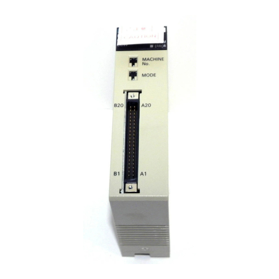
Section 1–3 Basic Operating Principles 1–2 Components In addition to the front-panel components described below, there is a DIP switch located on the back panel. Pin settings for this switch, which are de- scribed in Section 2–1 , determine certain aspects of Unit operation. When setting the switches, use a screwdriver if necessary. -
Page 14: I/O Configuration
Section 1–4 I/O Configuration data stored in the DM area of the PC. This data includes directions, speeds, positions, and other information necessary for effective control. Before the Position Control Unit can be operated, you must first input the essential data. This is generally done via the Programming Console, although you can also input data with the TEACH command. -
Page 15: Positioning System Principles
I/O Circuits in Section 2–2 .) The following config- uration diagrams show only the positioning system itself. Refer to the operat- ing manuals for other OMRON control devices for details on extended control system operation. - Page 16 Section 1–5 Positioning System Principles automatic adjustments. The C200H-NC112 Position Control Unit can be used in an open-loop system in conjunction with a stepping motor. In a closed-loop system, on the other hand, the PC controls an external pro- cess without human intervention. The servomotor provides direct feedback so that actual values (of positions, speeds, and so on) are continuously ad- justed to bring them more closely in line with target values.
-
Page 17: Open-Loop System
Section 1–5 Positioning System Principles Data Flow Position Control Unit C200H-NC112 Stepping motor driver Pulse train Stepping motor Pulse C200H PC generator External input interface Magnetizing Power distributor amplifier circuit Memory Pulse train Servomotor driver Servomotor Error counter Power amplifier (Positioning output) Tachogenerator Rotary encoder... -
Page 18: Semiclosed-Loop System
Section 1–5 Positioning System Principles Angle of rotation Angle of rotation Positioning output Positioning pulse Simplified Positioning The following diagram and parameters illustrate a simplified positioning sys- System Design tem. Reduction gear Feed screw pitch Object being positioned Stepping motor M: Reduction ratio P: Feed screw pitch (mm/revolution) V: Feed velocity of object being positioned (mm/s) - Page 19 Section 1–5 Positioning System Principles Servomotor driver Servomotor Target position Error counter Power amplifier Position output Tachogenerator Speed feedback Rotary encoder Position feedback (feedback pulses) 1, 2, 3... 1. First, the target position is transmitted to the error counter in units of en- coder pulses.
-
Page 20: Section 2 - Before Operation
SECTION 2 Before Operation Before the Position Control Unit can be operated, switch settings and wiring must be correct. This section presents the settings and functions of switches, provides examples of and precautions for wiring, and gives dimensions of Units both when unmounted and mounted. -
Page 21: Switch Settings
Section 2–1 Switch Settings 2–1 Switch Settings Always turn off PC power before setting the unit number switch. Use a regu- lar screwdriver, being careful not to damage the slot in the screw. Be sure not to leave the switch midway between settings. Switch Function Unit number... - Page 22 Deviation counter Deviation reset input counter reset 5 VDC Mode 3 This mode is used when a servomotor driver having an origin adjustment sig- nal (such as OMRON Model R88D) is used. Pulse NC112 Servomotor driver Origin 24 VDC proximity...
-
Page 23: Switch Settings
Section 2–1 Switch Settings separate CW and CCW pulses are output. When nondirectional pulses are output, the direction signal determines the direction of positioning. Set this pin in accordance with the specifications of the motor and motor driver to be used. - Page 24 Section 2–1 Switch Settings Origin proximity Origin (When searching for the origin in the CCW direction) Positioning axis ORIGIN SEARCH (Start) Origin (Stop) Origin (Stop) ORIGIN SEARCH (Start) CW limit Origin (Stop) ORIGIN SEARCH (Start) When the pin is set to OFF, ORIGIN SEARCH is executed completely at proximity speed (low speed).
- Page 25 Section 2–1 Switch Settings NO contact NC contact Pin 6: External Interrupt External interrupt processing is determined by pins 6 and 7 in combination Signal Type and with bit 06 of IR word n (n = 100 + 10 x unit number). See Section 4–10 for Pin 7: External Interrupt details.
-
Page 26: Switch Setting Examples
Section 2–1 Switch Settings Origin proximity Origin (Z phase) Pulse output Positioning axis ORIGIN SEARCH (Start) Origin (Stop) 2–1–1 Switch Setting Examples The examples in this section show switch settings for ORIGIN SEARCH in each of the four Position Control Unit modes. In every case, set the appropri- ate unit number and mode first, as described at the beginning of Section 2–1. - Page 27 Section 2–1 Switch Settings ORIGIN SEARCH Origin proximity signal Origin signal Pulse output Time Busy flag Example 2: Settings in In this example, the mode switch is set to 1 and the DIP switch pins are set Mode 1 as follows: CW/CCW output Origin search direction: CCW Origin proximity present...
- Page 28 Section 2–1 Switch Settings ORIGIN SEARCH Origin proximity signal Z-phase signal Time Pulse output Deviation counter reset output Approx. 30 ms Busy flag Example 3: In this example, the mode switch is set to 2 and the DIP switch pins are set Settings in Mode 2 as follows: CW/CCW output...
- Page 29 Section 2–1 Switch Settings ORIGIN SEARCH Origin proximity signal Z-phase signal Pulse output Time Deviation counter reset output Approx. 30 ms Driver completed input Busy flag Example 4: In this example, the mode switch is set to 3 and the DIP switch pins are set Settings in Mode 3 as follows: CW/CCW output...
-
Page 30: Wiring
Section 2–2 Wiring ORIGIN SEARCH Origin proximity signal Pulse output Time Origin adjustment command output Driver completed input Busy flag 2–2 Wiring External I/O Connections The example diagram below shows I/O connections. Position Control Unit C200H-NC112 C200H PC Control panel Emergency stop External interrupt switch... - Page 31 Section 2–2 Wiring Row B Pin no. Row A Emergency stop input (0V) Emergency stop input (12 to 24 VDC) External interrupt input (0V) External interrupt input (12 to 24 VDC) CW limit input (0V) CW limit input (12 to 24 VDC) CCW limit input (0V) CCW limit input (12 to 24 VDC) Origin input (0V)
- Page 32 Section 2–2 Wiring The connector pin numbers are as shown below. Be sure to perform con- nection correctly. Outline of protruding part Pin number markings View from the Soldered Side Differentiating Cables Output cables Input cables Assembling Connectors Two 8-mm M2 pan-head screws (short) Usable connectors: Four M2 nuts...
- Page 33 Section 2–2 Wiring I/O Circuits In the I/O circuits depicted in the following diagrams, pin numbers on the con- nector actually start from 1 at the bottom of the connector and run through 20 at the top.
- Page 34 Section 2–2 Wiring Outputs Provide a power supply of either 5 or 24 VDC. The internal circuit will be damaged if both the 5 and 24 VDC power sources are connected. Constant- voltage Power for output, 24 VDC circuit Power for output, 5 VDC Ω...
- Page 35 Section 2–2 Wiring Inputs Ω (12 to 24 VDC) Origin proximity input (Select either NO or NC Ω inputs via the back-panel DIP switch.) (0 V) Ω (12 to 24 VDC) Origin input (Select either NO or NC Ω inputs via the back-panel DIP switch.) (0 V) (+Z)
-
Page 36: Input Connection Examples
Section 2–2 Wiring 2–2–1 Input Connection Examples Each input is provided with both an NO (normally open) input and an NC (normally closed) input that can be used according to specifications. Leave unused NO inputs open and connect unused NC inputs to the power supply. - Page 37 Pins A11 and B11 are internally rectified so that they can be used bi-direc- tionally. Origin Line Driver Input (A8, B8) Ω Leave these pins open Ω OMRON R88D-EP Servomotor Driver (Marketed in Japan) –Z Use a separate power source for...
-
Page 38: Output Connection Examples
Power supply (24 VDC) – Ω OMRON R88D-EP Servomotor Driver (Marketed in Japan) Ω The driver completed input signal is also used as an origin search completed signal in modes 2 and 3. Adjust the setting of the servomotor driver so that this signal always turns OFF while the servomotor is operating, and ON when the motor stops. - Page 39 Section 2–2 Wiring 5-VDC power Motor driver supply Position Control Unit (rated at 5 VDC) – Where load current = approx. 4 mA 24-VDC input 5-VDC input Ω 1.6 k Approx. 3 mA (–) CCW pulse Approx. CCW input Approx. 4 mA output 7 mA Ω...
- Page 40 Section 2–2 Wiring Example 1: Outputting CW and CCW Pulses with a 5 VDC Power Supply 5-VDC (Do not share this power supply with other pins.) power Position Control Unit supply Motor driver (rated at 5 VDC) – Ω (Example: R = 220 24-VDC input 5-VDC input Ω...
- Page 41 Section 2–2 Wiring 24-VDC (Do not share this power source with other pins.) power supply Position Control Unit Motor driver (rated at 5 VDC) – Ω (Example: R= 220 24-VDC input 5-VDC input Ω 1.6 k (–) CCW pulse output Approx.
- Page 42 Other Outputs with a 5-VDC Power Supply Deviation Counter Reset When the Position Control Unit is set to modes 1 or 2, this signal is output for Output approximately 20 ms following completion of ORIGIN SEARCH. OMRON Servomotor Driver R88D-EP (Marketed in Japan) 5-VDC power supply –...
- Page 43 Section 2–2 Wiring Example 5: Stepping-Motor Driver Connection Stepping motor driver UDX5114 Position Control Unit (Manufactured by Oriental Motor) –CW +CCW Stepping motor UPH599 –CCW (Manufactured by Oriental Motor) Power for output 5 VDC Limit switch (NO or NC contact) Origin proximity 24V 0V...
- Page 44 Section 2–2 Wiring OMRON R88D-EP/SR Servomotor Driver (Marketed in Japan) Position Control Unit –CW +CCW Servomotor R88M-E/S (Marketed in Japan) CCW B3 –CCW Power supply 13, 14 5 VDC for output Deviation counter RESET reset output Origin adjustment command output Z-phase input –Z...
- Page 45 Mode 3 This example diagram shows the use of the origin adjustment function of the OMRON R88D-EP/SR Servomotor Driver. The driver completed input (INP) is used as the origin search completed signal as well as the driver completed signal. Using this servomotor driver, it is possible to determine the origin quite accurately.
- Page 46 CW limit Emergency stop NC limit switch Mode 3: Connecting an The following wiring diagram shows how to connect an OMRON R88D-V10 OMRON V-Series AC AC Servomotor Driver. Since this wiring is used with mode 3, the ORIGIN Servomotor Driver...
-
Page 47: Wiring Precautions
Section 2–2 Wiring Position control AC Servodriver AC Servomotor Board 3F8GM-10V K88D-V10 R88M-V20040 (Marketed in Japan) (Marketed in Japan) (Marketed in Japan) Position Control Unit Special-use 1 +5V Forward cable R1 1 Red and white 2 FP input R2 2 Blue and white 3 +5V Reverse... -
Page 48: Dimensions
Section 2–3 Dimensions DC relays AC relays Diode for surge absorption Surge absorber – Note Connect the diode and surge absorber as close as possible to the relay. Use a diode capable of withstanding a voltage five times greater than the circuit voltage. - Page 49 Section 2–3 Dimensions Mounted Dimensions (Unit: mm) Rack Cable Approx. 200...
-
Page 50: Section 3 - Operation
SECTION 3 Operation This section covers all aspects of Position Control Unit operation other than commands, which are covered in the follow- ing section. Included in this section are the basic operating procedure, the type of output pulses possible, the basic data format and configuration, some special features to aid operation (such as flags, zone settings, backlash compensation and internal limits) and the internal data calculation methods used in processing user-input data. -
Page 51: Operational Flow
Section 3–1 Operational Flow 3–1 Operational Flow The basic procedure used to operate the Unit initially is outlined below. Refer to applicable sections of the manual for details on each of these steps. Item Procedure Refer to Start Wiring Section 2–2 Origin, origin proximity, CW/CCW Wiring external limits, emergency stop, external in-... - Page 52 Section 3–1 Operational Flow Procedure Item Refer to: AR area error and Trial run Position Control Restart by resetting restart bits for Unit reads DM area power or AR area Special I/O Units restart bit ORIGIN SEARCH, manual operation, START, etc. Alarm/error LED lit? Error exists...
-
Page 53: Output Pulses
Section 3–3 Writing Data 3–2 Output Pulses The Position Control Unit can be set to output either independent CW and CCW pulses or a nondirectional pulse and a direction signal. Set pin #1 on the back-panel DIP switch to designate the desired type of output. (See Sec- tion 2–1 .) CW and CCW Pulse Outputs CW pulse train... -
Page 54: Data Configuration And Allocation
Section 3–4 Data Configuration and Allocation Programming Console Display Key Input Sequence D1824D1823D1822 0012 5000 2000 The above procedure prepares DM 1824 for change, and new data can be keyed in. Pressing the CHG key again moves the cursor to DM 1823. After inputting data, press the write key to execute the rewrite. - Page 55 Section 3–4 Data Configuration and Allocation ignated in this manual as n , can be computed from the unit number as fol- lows: n = 100 + 10 x unit number. Each Unit is also allocated 100 consecutive words as a fixed data area. These words are in the DM area and run from DM 1000 through DM 1999.
- Page 56 Section 3–4 Data Configuration and Allocation Word START Initial positioning Speed Beginning word PC data area (for Valid initial positioning action number coefficients TRANSFER TRANSFER DATA) action number DATA) ORIGIN SEARCH ORIGIN RETURN RELEASE PROHIBIT READ ERROR CHANGE SPEED Deviation counter reset Valid speed coefficient Origin adjustment...
-
Page 57: Dm Area Data Format
Section 3–7 DM Area Allocation 3–5 DM Area Data Format Data is allocated either by bit or by word, though it is often input and output by decimal digit, i.e., four bits (BCD). Position data is held in two adjacent words, generally with a direction digit, in the following format. - Page 58 Section 3–7 DM Area Allocation The numbers shown for the DM words in the table represent only the final two digits of each word number. In other words, the first two digits (which would be the same for all words) are not shown. The value of the first two digits can be obtained by computing the first DM word allocated to the Unit.
-
Page 59: Zones
Section 3–7 DM Area Allocation Function Function Function Transfer no. Transfer no. Initial position nos.; speed nos. Positioning Positioning Origin compensa- action #4 action #15 tion and direction Backlash compensation Positioning Positioning CW limit action #5 action #16 CCW limit Positioning Positioning action #6... - Page 60 Section 3–7 DM Area Allocation present position is within the zone; OFF (0) when it is not. You can set zones to cover a wide range of positions or only part of a single positioning action. Zones can also be set to overlap, if you wish. For an application example, see programming example 8 in Section 5 .
-
Page 61: Backlash Compensation
Section 3–7 DM Area Allocation 07 06 Zone 0 flag 0 Outside zone Zone 1 flag 1 Inside zone Zone 2 flag 3–7–2 Backlash Compensation There may be a certain amount of mechanical play present in gears, that will affect positioning accuracy when the direction of positioning actions changes. You can compensate for this by using backlash compensation. -
Page 62: Internal Cw/Ccw Limits
Section 3–7 DM Area Allocation STOP executed Í Í Í Í Time Compensation Stop position 3–7–3 Internal CW/CCW Limits You can also make settings in the DM area to place internal limits on rotation of the axis on both the CW and CCW sides of the origin. Internally set value of CCW limit Internally set value of CW limit Positioning axis... - Page 63 Section 3–7 DM Area Allocation Settings between 92 and 250,000 pps 6,000,000 Actual speed (pps) = INT(6,000,000/set value) where, INT: Nearest integer INT(6,000,000/set value): Divider ratio pps: Pulses per second Pulse output (actual speed) Divider 6 MHz The slight difference occurs because a 6-MHz source clock is divided by the integral divider ratio.
- Page 64 Section 3–7 DM Area Allocation Trapezoidal An internal calculation process is used to create a trapezoidal figure from Acceleration/Deceleration speed, acceleration, and deceleration settings. Speed Time When accelerating or decelerating between two speeds, the speed is varied in a stepwise fashion. To achieve this, acceleration and deceleration tables are created internally when the Unit is first operated or when TRANSFER DATA is used to alter data.
- Page 65 Section 3–7 DM Area Allocation The divider ratios for all steps are calculated and set in a table. Target (step) speed Divider ratio Step ∆υ MIN + ∆υ MIN + 2 Example Start speed 0 (pps) Maximum value of speed data Nos. 1 to 15 20000 (pps) Acceleration 100 (pps/1ms)
- Page 66 Section 3–7 DM Area Allocation Data Transfer Time When executing TRANSFER DATA, the Busy flag (bit 12 of word n + 5) will be ON during data transfer and processing for the following time periods: Positioning Action Data Only (positioning actions #0 through #19): Maximum: 0.1 s + k (scan time) When Speed Data (Transfers #20 through #25) Is Included: Maximum: 0.2 s + k (scan time)
-
Page 67: Section 4 - Commands
SECTION 4 Commands The Position Control Unit provides thirteen commands to execute automatic and manual positioning actions, define and establish position, transfer data, and handle interrupts and errors. Any given command is executed when the program in the PC turns ON the appropriate command bit in the IR area. In addition to the command bits themselves, the IR area contains certain other data which are necessary for executing commands. -
Page 68: Start
Section 4–1 START 4–1 START Execution of positioning actions begins when the program turns ON the START command bit, bit 00 of IR word n (effective on signal’s rising edge). The actions are executed in order from either the initial positioning action designated in the DM area or that designated in the IR area, depending on another setting you make in the IR area. -
Page 69: Positioning Actions
Section 4–2 Positioning Actions Target speed Target speed Acceleration Acceleration Time Initial speed #0 Initial speed number other than 0 Speeds DM words m+82 through m+96 Set each word to a value between 0000 and 9999 pps (4 digits) You can set up to fifteen speeds in these DM words, numbered from one to fifteen. - Page 70 Section 4–2 Positioning Actions The fundamental unit of positioning is the positioning action. In C200H-NC112 Position Control Units, each positioning action is defined by its completion code, dwell time, output code, speed number, and target posi- tion, all of which are explained below. Positioning actions are generally referred to by number and completion code.
-
Page 71: Positioning Actions
Section 4–2 Positioning Actions 2: Continuous If you designate a positioning action as “continuous”, then as soon as the target position for that positioning action is reached, the next positioning ac- tion is started. The first target position is reached at the target speed set for the next positioning action, so that the next positioning action can be ex- ecuted immediately. - Page 72 Section 4–2 Positioning Actions action was started is reset and positioning is executed according to the data set for the positioning action. The Unit will not calculate the present position, and the No-origin flag (bit 11 of IR n+5) will go ON during operation. The di- rection of pulse output is determined by the direction bit set for the position- ing action.
- Page 73 Section 4–2 Positioning Actions If the target position is near the position at which STOP is executed, pulse output will cease before deceleration is completed. However, no error code will be output. DM word m+22, bits 07 to 04 Dwell Time Set to a value between 0 and F (hex).
-
Page 74: Ir Area Settings
Section 4–2 Positioning Actions m+23 x10 m+24 m+23 Sign Direction m+24 CW absolute value CCW absolute value CW increment CCW increment Maximum values are as follows: 8,388,606 pulses CCW: 8,388,607 pulses Absolute values are measured from the origin. Increment values are mea- sured from the present position. - Page 75 Section 4–2 Positioning Actions START IR word n, bit 00 When the program turns this bit ON (i.e., sets it to 1), bits 01 and 07 are re- ferred to and positioning begins. Valid Initial Positioning IR word n, bit 01 Action Number This is used when the initial positioning action number is designated in the I/O refresh areas.
-
Page 76: Execution Examples
Section 4–2 Positioning Actions Speed Acceleration Coefficient: of 1.5 Target speed (coefficient not used or set at 1.0) Coefficient: of 0.5 Time Deviation Counter Reset IR word n+2, bit 06 Bit 06 is only valid during STOP. The deviation counter reset output (A6, B6) is ON if this bit is set to 1, and OFF if it is set to 0. - Page 77 Section 4–2 Positioning Actions time); following the pause, the next positioning action will start automatically. Positioning actions #4 and #5 are thus executed consecutively, with a preset pause in between. Since the completion code for positioning action #5 is set at 1 (single), positioning will stop after completion of this sequence.
- Page 78 Section 4–2 Positioning Actions START (IR n, bit 00) Pulse output Time 0.5 s 1.0 s Positioning Completed flag (IR n+5, bit 00) Busy flag (IR n+5, bit 12) Example 3: Using START Positioning sequences combining several pause and/or continuous position- with Single or Bank End ing actions normally are ended by a single or bank end positioning action.
-
Page 79: Origin Search
Section 4–3 ORIGIN SEARCH START command IR n, bit 00 #1, continuous #2, single Pulse output #0, single Time Positioning Completed flag IR n+5, bit 00 Busy flag IR n+5, bit 12 When positioning ends, the positioning action number is changed as follows: Positioning action number IR n+7, bits 07 to 00 Output code... -
Page 80: Ir Area Settings
Section 4–3 ORIGIN SEARCH higher than the ORIGIN SEARCH high speed number. If there is no origin proximity signal, the speed designated here is used for the entire ORIGIN SEARCH operation. ORIGIN SEARCH DM word m+1, bits 07 to 04 High Speed Number Set to an integer between 1 and F (hex). -
Page 81: Execution Examples
Section 4–3 ORIGIN SEARCH (n = 100 + 10 x unit number) ORIGIN SEARCH command bit (ORIGIN SEARCH is started when this bit is turned on) 4–3–3 Execution Examples The following examples show the relationships among the mode number, DIP switch pin no. 3 (origin proximity present/absent), DIP switch pin no. 8 (origin proximity reverse present/absent) and operation. - Page 82 Section 4–3 ORIGIN SEARCH Example 1: As illustrated below, use the origin proximity signal to ensure sufficient decel- When Origin Proximity eration time when using a slit disc for the origin signal. In this example, DIP Reverse is Enabled switch pins 3 and 8 are ON. Refer to Section 2–1 . Stepping motor Sensor Origin signal...
- Page 83 Section 4–3 ORIGIN SEARCH Example 2: In this example, DIP switch pin 3 is ON and 8 is OFF. (Refer to Section 2–1 .) When Origin Proximity The origin proximity signal and origin signal each occur once. Reverse is Disabled Origin proximity signal Origin signal...
- Page 84 Section 4–3 ORIGIN SEARCH Example 3: When the origin proximity signal is not needed, set DIP switch pin 3 to OFF No Origin Proximity Signal and use only the origin signal. Positioning will be carried out completely at proximity speed (low speed). Origin signal Pulse output Origin (Stop)
- Page 85 Section 4–3 ORIGIN SEARCH Example 1: Use the origin proximity signal to ensure sufficient deceleration time when the When Origin Proximity origin proximity reverse is needed. In this example, DIP switch pins 3 and 8 Reverse is Enabled are ON. For DIP switch settings, refer to Section 2–1 . Origin proximity signal Origin signal...
- Page 86 Section 4–3 ORIGIN SEARCH tect a different origin signal. Therefore, be sure that the origin proximity signal period is long enough, i.e., at least as long as the deceleration period. The following diagram shows what can happen if this is not done. Origin proximity signal Origin signal...
- Page 87 Section 4–3 ORIGIN SEARCH Origin proximity signal Origin signal Pulse output Positioning axis Origin (Stop) ORIGIN SEARCH (Start) (The origin is sought after deceleration has ended.) Note that if the origin signal is been input during deceleration, the stop posi- tion differs depending on the length of the deceleration period.
- Page 88 Section 4–3 ORIGIN SEARCH Origin proximity signal Origin signal Pulse output : Number of pulses for deceleration period (p) : ORIGIN SEARCH high speed (pps) V : Proximity speed (pps) R: Deceleration data (pps/ms) = [(V ) x (V – V /1000 x R)]/2 = (V –...
- Page 89 Busy flag Dwell time Mode 3 Mode 3 makes use of the origin adjustment functions of OMRON Servomotor Drivers R88D-EP and R88D-SR. The servomotor’s driver completed signal (INP) is used as the origin search completion signal. Do not use an origin, Z-phase, or deviation counter reset signal.
- Page 90 Section 4–3 ORIGIN SEARCH Origin proximity signal Origin adjustment command Positioning completed signal Pulse output Time Origin (Stop) ORIGIN SEARCH (Start) Busy flag When the servomotor driver receives the origin adjustment signal (H.RET) from the Position Control Unit, the deviation counter of the servomotor driver is internally reset by the Z-phase signal (which is output by the encoder) and the servomotor driver stops.
- Page 91 Section 4–3 ORIGIN SEARCH Example 2: In this example, origin proximity reverse is not used. DIP switch pin 3 is ON When Origin Proximity and pin 8 is OFF. The origin adjustment command is output after deceleration Reverse is Disabled has ended.
-
Page 92: Completion Examples
Section 4–3 ORIGIN SEARCH Origin proximity signal Z-phase signal (Long deceleration time) Pulse output Stop Time Origin adjustment command (Short deceleration time) Stop Pulse output Time Origin adjustment command 4–3–4 Completion Examples Completion Patterns With an Origin Proximity Signal The following two example diagrams both illustrate completion of ORIGIN SEARCH when an origin proximity signal is present (i.e., when DIP switch no. - Page 93 Section 4–3 ORIGIN SEARCH Example 1: Without Origin Compensation Origin proximity signal Origin signal Deceleration Proximity speed Pulse output High speed Time At-origin flag word n+5, bit 02 No-origin flag word n+5, bit 11 Busy flag word n+5, bit 12 Example 2: With Origin Compensation Origin proximity signal Origin signal...
-
Page 94: Origin Return
Section 4–4 ORIGIN RETURN no. 3 is OFF). There is an origin compensation value set in the second exam- ple, but not in the first. Example 1: Without Origin Compensation Origin signal Proximity speed Pulse output Time At-origin flag word n+5, bit 02 No-origin flag word n+5, bit 11 Busy flag... -
Page 95: Dm Area Settings
Section 4–4 ORIGIN RETURN n. When the program turns this bit ON (effective on signal’s rising edge), the Position Control Unit outputs pulses until the origin is reached. As with ORI- GIN SEARCH, the Position Control Unit uses data stored in the DM area when executing ORIGIN RETURN. - Page 96 Section 4–4 ORIGIN RETURN ORIGIN RETURN word n, bit 03 ORIGIN RETURN speed Deceleration Initial speed Acceleration Pulse output Initial speed Time Origin (Stop) ORIGIN RETURN (Begin) [IN refresh data area flags] At-origin flag word n+5, bit 02 Busy flag word n+5, bit 12...
-
Page 97: Release Prohibit
Section 4–5 RELEASE PROHIBIT 4–5 RELEASE PROHIBIT When Position Control Unit operation is stopped due to an emergency stop, CW limit, or CCW limit signal, (i.e., when the NC input of any of these turns ON), further pulse output is prohibited. In order to resume pulse output, it is necessary to cancel this prohibition by means of the RELEASE PROHIBIT command bit (bit 04 of word n) and release of the external emergency stop switch. - Page 98 Section 4–5 RELEASE PROHIBIT Input Emergency stop signal START IR n, bit 00 RELEASE PROHIBIT IR n, bit 04 Pulse output Time Emergency Stop flag IR n+5, bit 04 Origin search begun Error flag IR n+5, bit 05 No-origin flag IR n+5, bit 11 Turns OFF when origin search is completed Busy flag...
-
Page 99: Read Error
Section 4–6 READ ERROR CW limit signal START IR n, bit 00 RELEASE PROHIBIT IR n, bit 04 HIGH-SPEED JOG IR n, bit 11 JOG direction IR n, bit 12 Pulse output Time Error flag IR n+5, bit 05 No-origin flag IR n+5, bit 11 Busy flag IR n+5, bit 12... -
Page 100: Execution Example
Section 4–6 READ ERROR Alarm flag: Set to 1 when an alarm code has been generated Error flag: Set to 1 when an error has occurred Error code (or alarm code) IR word n+6 shows four digits in BCD when displayed on the Programming Console. -
Page 101: Reset Origin
Section 4–8 TEACH Programming Console Display: Key sequence: c106 1501 10005 c106 ^ OFF 1501 10005 c106 ^ OFF 5000 4–7 RESET ORIGIN The origin is simply the point which is designated as 0 at any given time. You can redefine it whenever you wish by using RESET ORIGIN. When the pro- gram turns ON the RESET ORIGIN command bit, bit 08 of word n (effective on signal’s rising edge), it redefines the present position as the origin. -
Page 102: Ir Area Settings
Section 4–8 TEACH Present positioning axis position DM 1052 DM 1053 DM 1054 Data set using TEACH is valid immediately and can be used for positioning actions without turning off the power or transferring data. Note that data re- written using the Programming Console is not valid until data has been trans- ferred again. -
Page 103: Transfer Data
Section 4–9 TRANSFER DATA and writes the present position into words DM 1053 and DM 1054 as an ab- solute position (i.e., relative to the origin). Programming Console Display Key sequence 10013 ^ OFF 10013 Low-speed JOG ^ ON c10110013 0000^ OFF c10110013 1000^ OFF... -
Page 104: Normal Transfer
Section 4–9 TRANSFER DATA C200H PC Position Control Unit #5 Data table DM 1500 to 1599 Automatically transferred at start-up or restart via AR area Parameters restart bit. Positioning actions Speeds IR area, LR area, Acceleration HR area, I/O memory etc. -
Page 105: Ir Area Settings
Section 4–9 TRANSFER DATA consecutively by number, starting with the beginning transfer number set in the IR area. Up to 26 transfers (three words each) can be made each time TRANSFER DATA is executed. Each transfer consists of one positioning ac- tion, three speeds, or the speed units, acceleration, and deceleration. - Page 106 Section 4–9 TRANSFER DATA Beginning word number Data Area Set a word Number of transfers number in 4-digit BCD code Beginning Transfer Number IR word n+2, bits 15 to 08 Set an integer between 00 and 25. This is the number of the first word to be transferred. The requested number of words will be transferred starting from this word.
-
Page 107: Present Position Preset
Section 4–9 TRANSFER DATA Preparation of data in PC’s data areas Set necessary information in IR area. Beginning transfer number IR n+2, bits 15 to 08 Beginning word number IR n+3 PC data area/no. of transfers IR n+4 TRANSFER DATA IR n, bit 10 Transfer Completed flag IR n+5, bit 10... -
Page 108: Present Position Preset
Section 4–9 TRANSFER DATA Direction Direction n+5, bit 11 XFER (70) #0002 HR 00 HR 00 Direction HR 01 Data Preparation Data must be prepared in the same manner as for normal execution of TRANSFER DATA, except that only two words indicating the target position are necessary. - Page 109 Section 4–9 TRANSFER DATA Beginning word number Data Area Set a word Number of transfers number in (Not required) 4-digit BCD code TRANSFER DATA IR word n, bit 10 Command Bit After the above settings are made, TRANSFER DATA is executed by turning ON this bit.
-
Page 110: 4-10 Manual Operations
Section 4–10 Manual Operations Set necessary information in IR area. Present position preset IR n+2, bit 15 Beginning word number IR n+3 PC data area IR n+4 bits 07 to 00 TRANSFER DATA IR n, bit 10 Transfer completed flag IR n+5, bit 10 Busy flag IR n+5, bit 12... -
Page 111: 4-10-2 Ir Area Settings
Section 4–10 Manual Operations Speed Units DM word m+97 Acceleration Bits 15 to 00 of DM word m+98 Deceleration Bits 15 to 00 of DM word m+99 HIGH-SPEED JOG Speed DM word m+1, bits 15 to 12 Number Set an integer between 1 and F (hex). The speed number set here refers to one of the speeds set in DM words m+82 through m+96, and in DM word m+3, bit 04. -
Page 112: 4-10-4 Low-Speed Jog
Section 4–10 Manual Operations HIGH-SPEED JOG IR n, bit 11 HIGH-SPEED JOG speed Deceleration Acceleration Initial speed Initial speed Time Pulse output Initial position (start) End position (stop) Busy flag IR n+5, bit 12 4–10–4 LOW-SPEED JOG Feeding starts at the designated speed when the LOW-SPEED JOG com- mand bit (IR word n, bit 13) turns ON (effective on signal’s rising edge). -
Page 113: Inch
Section 4–11 External Interrupt Commands INCH IR n, bit 14 1 pulse (2.5 ms) Time Pulse output Approx. 5 ms Busy flag IR n+5, bit 12 ON for 1 scan when scan time is 12 ms or more. ON for 2 scans when scan time is less than 12 ms. 4–11 External Interrupt Commands You can stop positioning or change speeds with either the bits set in the IR area or by external interrupt signal input, depending on your DIP switch set-... - Page 114 Section 4–11 External Interrupt Commands STOP (command executed) Target speed #1 Acceleration Time START End position (positioning stops) Target speed #3 CHANGE SPEED (command executed) Target speed #1 Acceleration Deceleration Acceleration Target speed #2 Time START Connection for External Interrupt Signal The signal level’s rising edge is taken as the input signal.
-
Page 115: 4-11-1 Stop
Section 4–11 External Interrupt Commands bit. Execution through an external interrupt is available if bit 06 of word n is set to 1 and pin #6 on the DIP switch is OFF, or if pins #6 and #7 are both ON. - Page 116 Section 4–11 External Interrupt Commands START IR n, bit 00 Target speed #5 Target speed #8 Time START Stop (at target position Target position for action #0 for action #1) Positioning Completed flag IR n+5, bit 00 Busy flag IR n+5, bit 12 Example 2 The next diagram illustrates the case where STOP is executed before posi- tioning is finished.
- Page 117 Section 4–11 External Interrupt Commands START IR n, bit 00 STOP IR n, bit 15 (or external interrupt) Stops at target position Target speed #5 for action #1. Pulse output Time Target position for action #0 Positioning Completed flag IR n+5, bit 00 Busy flag IR n+5, bit 12 Positioning action number...
- Page 118 Section 4–11 External Interrupt Commands START IR n, bit 00 STOP IR n, bit 15 (or external interrupt) Target speed #5 Pulse output Time Target position for action #0 is passed. Positioning Completed flag IR n+5, bit 00 Error flag IR n+5, bit 05 Busy flag IR n+5, bit 12...
- Page 119 Section 4–11 External Interrupt Commands Example 4 When the target position is expressed as an increment, the positioning action will be automatically started over from the position arrived at after STOP was executed. START IR n, bit 00 STOP IR n, bit 15 Pulse output Time Positioning Completed flag...
- Page 120 Section 4–11 External Interrupt Commands ORIGIN RETURN IR n, bit 03 STOP IR n, bit 15 Time Pulse output Busy flag IR n+5, bit 12 STOP Executed flag IR n+5, bit 15 STOP During HIGH-SPEED If STOP is executed during HIGH-SPEED JOG, feeding will be stopped just as if the HIGH-SPEED JOG command bit (IR word n, bit 11) were reset to 0.
- Page 121 Section 4–11 External Interrupt Commands STOP During LOW-SPEED If STOP is executed during LOW-SPEED JOG, feeding will be stopped just as if the LOW-SPEED JOG command bit (IR word n, bit 13) were reset to 0. The command bit, however, will remain at 1. LOW-SPEED IR n, bit 13 STOP...
- Page 122 Section 4–11 External Interrupt Commands START IR n bit 00 STOP (first time) IR n, bit 15 Pulse output Time Positioning Completed flag IR n+5, bit 00 Busy flag IR n+5, bit 12 No-origin flag IR n+5, bit 11 Positioning is already started, but the flag turns OFF one scan later.
-
Page 123: 4-11-2 Change Speed
Section 4–11 External Interrupt Commands 4–11–2 CHANGE SPEED CHANGE SPEED can only be executed during positioning initiated with START. When executing CHANGE SPEED several times consecutively, you can either choose to have speed numbers incremented one by one, or select specific speed numbers to be executed in any order. -
Page 124: Section 5 - Programming Examples
SECTION 5 Programming Examples This section contains examples of possible applications of Positioning Control Unit commands, inputs, and outputs. The first example (see Section 5–1) shows the minimum data required for operation. The second example (Section 5–2) shows the use of only one positioning action under START augmented by RESET ORIGIN. Section 5–3 demonstrates the use of external switches to control positioning actions, while Sections 5–4 and 5–5 show use of TRANSFER DATA: the example in Section 5–4, from the PC, and in Section 5–5, from external switches. -
Page 125: Operation With Minimum Data (Displaying Jog Positions)
Section 5–1 Operation with Minimum Data (Displaying JOG Positions) 5–1 Operation with Minimum Data (Displaying JOG Positions) Wiring The wiring shown below is the simplest possible for Position Control Unit op- eration. Hand-held Programming Console Position Control Unit #0 C200H PC C200H-PR027 Emergency stop CW limit... -
Page 126: Positioning At Intervals Using Reset Origin
Section 5–2 Positioning at Intervals Using RESET ORIGIN Monitor the RESET ORIGIN command bit. 10008 c109 c108 ^ OFF 0999 9911 Reset the present position. 10008 c109 c108 ^ OFF 0000 0000 Set LOW-SPEED JOG command bit. Programming Console Display 10013 c109 c108 ^ ON 0000 2340 Indicates changes in present po-... - Page 127 Section 5–2 Positioning at Intervals Using RESET ORIGIN Configuration Position Control Unit C200H PC Emergency stop CW limit CCW limit Origin Origin proximity 24 VDC Operation Feeding is executed to positions lying at equal distances in the same direc- tion from a specific point, repeatedly using the same positioning action and then RESET ORIGIN.
-
Page 128: Feeding Selectively With Start
Section 5–3 Feeding Selectively with START Programming ORIGIN Initial Initial Start switch RETURN speed position DIFU(13) 03000 speed Busy (flag) 1 to F 0 to F 0 to 19 DM 1000 1 0 0 0 03000 10512 HIGH- LOW- ORIGIN Origin 10002 DM 1001... - Page 129 Section 5–3 Feeding Selectively with START ORIGIN Initial Initial RETURN speed position speed 1 to F 0 to F 0 to 19 DM 1000 1 0 0 0 HIGH- LOW- ORIGIN Origin DM 1001 1 2 1 2 SPEED SPEED SEARCH prox.
-
Page 130: Transfer Data From Other Pc Areas
Section 5–4 TRANSFER DATA from Other PC Areas Origin reset switch 10008 RESET ORIGIN 25313 Valid initial positioning action no. 10001 Input A Selects positioning action #0 MOV (21) #0000 Input B Selects positioning action #1 MOV (21) #0001 Selects positioning action #2 Input C MOV (21) #0002... - Page 131 Section 5–4 TRANSFER DATA from Other PC Areas Data To Be Transferred The transfer data is entered in DM words 0010 to 0018. The data and posi- tioning actions are shown below. DM 0010 3 0 0 2 DM 1084 DM 0011 9 0 0 0 Speed #3...
-
Page 132: Transfer Data From External Switches
Section 5–5 TRANSFER DATA from External Switches Program 00407 (Transfer PB) DIFU (13) 04001 Transfers data from DM 0010 when 00407 is set. Re-transfers data from DM 1022 when 00407 is reset. DIFU (14) 04002 (Three positioning actions transferred, beginning with 04001 MOV (21) DM 0010) - Page 133 Section 5–5 TRANSFER DATA from External Switches Configuration IR 000 IR 002 IR 003 Positioning C200H Control 16 bits 16 bits 16 bits Unit #0 Thumbwheel SW (leftmost digits of positioning data) Thumbwheel SW (rightmost digits of positioning data) SW1 (00010) SW2 (00000) Driver/motor Others...
- Page 134 Section 5–5 TRANSFER DATA from External Switches Program (SW 1) (SW 2) 00010 00000 DIFU (13) 03000 Data transfer switches (SW 2) (SW 1) 00000 00010 DIFU (13) 03001 Start switches 03000 10512 03002 MOV (21) Beginning action no. #0000 (busy flag) Origin re- (positioning action #0).
-
Page 135: Using Start To Carry Out Positioning Actions
Section 5–6 Using START to Carry Out Positioning Actions 5–6 Using START to Carry Out Positioning Actions Wiring (Details Omitted) PR027 ID211 ID212 OD211 NC112 OUT, 8 bits 16 points 12 points Position Control C200H Unit #0 Motor Driver Word 0 Word 1 Word 2 100 words... - Page 136 Section 5–6 Using START to Carry Out Positioning Actions Feeding Pattern 2000 1000 #0, single #1, single 10000 20000 4000 4000 4000 3000 T = 0.5 s T = 1.0 s T = 1.0 s #3, pause #5, single #2, pause #4, pause 30000 40000...
- Page 137 Section 5–6 Using START to Carry Out Positioning Actions Program 00000 10002 ORIGIN SEARCH 00001 RELEASE PROHIBIT 10004 00002 INCH/JOG direction 10012 00003 10011 HIGH-SPEED JOG 00004 10013 LOW-SPEED JOG 00005 10000 START 00006 10001 Valid initial positioning action number 00007 10015 STOP...
- Page 138 Section 5–6 Using START to Carry Out Positioning Actions Function Function Function 1 1 1 Transfer no. Transfer no. Initial position nos.; speed nos. 2 3 4 Positioning Positioning 2 0 0 Origin compensa- action #4 action #15 tion and direction 0 0 0 Backlash 0 0 0...
-
Page 139: Using Origin And Origin Proximity Signals
Section 5–8 Using Zones to Control Jogging 5–7 Using Origin and Origin Proximity Signals Configuration Position Control Unit C200H PC Emergency stop CW limit CCW limit Origin Origin proximity 24 VDC DIP Switch Settings Pin 3 ON (Designating presence of origin proximity signal) Pin 4 ON (Designating N.O. - Page 140 Section 5–8 Using Zones to Control Jogging operations are possible in zone 1 except for the part of it occupied by zone 0. In zone 0, CCW manual feeding is prohibited. 5000 Zone 0 Zone 1 DM Area Settings (Zone Data) DM 1009 0 3 0 0 Zone 0 CW limit...
-
Page 141: Setting Speeds
Section 5–10 Using a Multiple Bank Program 5–9 Setting Speeds Multiplying the Speed Unit by 10 DM 1003 X X 0 X Multiplies speed unit by 10 DM 1082 2 0 0 0 x10 Speed No. 1 = 20000 pps DM 1083 1 0 0 0 Speed No. - Page 142 Section 5–10 Using a Multiple Bank Program First Bank The data for one bank is entered into positioning action numbers 0, 1, and 2. (Positioning Action Numbers 0 to 2) DM 1084 DM 1022 3 0 0 2 Speed No. 3 DM 1023 0 0 0 0 DM 1085...
- Page 143 Section 5–10 Using a Multiple Bank Program Program (Unit #0) Start switch DIFU (13) 10000 10501 (Bank End flag) DIFU (13) 03000 #0 assigned switch 10000 03000 03101 Designates #0 as the next positioning action 03100 after the bank ends 03100 MOV (21) #0000...
-
Page 144: Section 6 - Error Processing
SECTION 6 Error Processing This section covers the procedures for handling errors and alarms during Position Control Unit operation. It includes er- ror codes, alarm codes, error and alarm indicators, troubleshooting from the PC, and AR area Restart bits. For a complete list of alarm codes, see Appendix A. -
Page 145: Alarms And Errors
Section 6–4 Error Code Output 6–1 Alarms and Errors Alarms Whenever the Position Control Unit is powered up or data is transferred into the Unit, checks are performed to ensure that the data is in proper form and can be used for operation. If an error exists in speed or positioning action data at this time, an alarm code is generated. - Page 146 Section 6–4 Error Code Output If IR word n+6 is displayed on the Programming Console and there are no errors or alarms, the display will be “0000”. If an error or an alarm is gener- ated, the code will be displayed. If only one error or alarm has been gener- ated, executing READ ERROR will have no effect.
-
Page 147: Troubleshooting From The Pc
Section 6–5 Troubleshooting from the PC Programming Console Display: Key sequence: c106 1501 10005 c106 ^ OFF 1501 10005 c106 ^ OFF 5000 Clearing Errors For details on clearing errors, refer to Appendix E and Appendix F . An outline is given below. -
Page 148: Basic Troubleshooting Chart
Section 6–6 Basic Troubleshooting Chart Unit number AR 0000 AR 0001 AR 0002 AR 0003 AR 0004 AR 0005 AR 0006 AR 0007 AR 0008 AR 0009 Restart Bits The following Restart bits are turned off, on, then back off again to restart Special I/O Units. - Page 149 Noise a conceivable cause. Check according to wiring precautions at the end of Wiring. Malfunction in hardware Malfunction in motor or possible. motor driver possible. Contact Omron agent and Contact Omron agent. replace component.
-
Page 150: Detection Of Abnormal Pulse Outputs
Section 6–7 Detection of Abnormal Pulse Outputs 6–7 Detection of Abnormal Pulse Outputs The Position Control Unit outputs pulse trains in accordance with the pro- grammed data. When tracing an abnormality, the following should be taken into consideration. Number of Pulses in Pulse The Unit only outputs the number of pulses required to reach the target posi- Train tion. - Page 151 Section 6–7 Detection of Abnormal Pulse Outputs Connections to an Up/Down Counter 5 VDC power Position Control Unit supply Motor driver ( for 5V input ) 24 VDC power supply input Ω ( example : R = 220 5 VDC power supply input Ω...
-
Page 152: Appendix
Appendix A Standard Models Name Specifications Model 100 to 120/200 to 240 VAC C200H-CPU01-E 24 VDC C200H-CPU03-E 100 to 120/200 to 240 VAC. Compatible with SYSMAC LINK and C200H-CPU11-E SYSMAC NET Link Units; Clock funcion provided; new instrucitons added. Position Control Unit 1 axis. -
Page 153: B - Specifications
Appendix B Specifications General Conforms to C-series specifications. Performance Item Specifications Number of axes 1 per Unit Positioning system Automatic trapezoidal acceleration/deceleration system Positions –8,388,607 pulses to +8,388,606 pulses Number of positioning actions Speeds 1 to 250,000 pps Number of speeds Acceleration/deceleration 2 to 2,000 pps Origin search... - Page 154 Appendix B Specifications Origin Signal Input Item Connector pins Specifications Response time Open collector signal A11, B11 All the above specifications apply, Mode 0: 1 ms max. except that the input current is 6 Modes 1 and 2: 0.1 ms max. mA (12 V) to 13 mA (24 V).
- Page 155 Appendix C DM Area Allocations In these tables, m = 1000 plus 100 times the unit number. Word Function Initial position no., 00 to 19 (BCD): Initial START and START after bank end. 07 to 00 Initial speed no., 0 to F (hexadecimal) 11 to 08 ORIGIN RETURN speed no., 1 to F (hexadecimal) 15 to 12...
- Page 156 Appendix C DM Area Allocations Word Function Zone 0: CCW side m+11 15 to 00 m+12 m+11 (7 digits BCD with direction direction digit) m+12 15 to 00 0 CW 1 CCW Zone 1: CW side m+13 15 to 00 m+14 m+13 (7 digits BCD with...
- Page 157 Appendix C DM Area Allocations Word Function m+21 Not used Completion code 0: Single 3: Bank end 03 to 00 1: Pause 4: Extended 2: Continuous 5: Ext. w/ positioning Dwell time 0 to F (hexadecimal) in units of 0.1 s 07 to 04 m+22 Output code...
- Page 158 Appendix C DM Area Allocations Word Function m+52 Positioning action #10 m+53 Data format same as for positioning action #0 (Transfer data #10) m+54 m+55 Positioning action #11 m+56 Data format same as for positioning action #0 (Transfer data #11) m+57 m+58 Positioning action #12...
- Page 159 Appendix C DM Area Allocations Word Function m+91 Speed #10 0000 to 9999 (BCD) 15 to 00 m+92 Transfer data #23 Speed #11 0000 to 9999 (BCD) 15 to 00 m+93 Speed #12 0000 to 9999 (BCD) 15 to 00 m+94 Speed #13 0000 to 9999 (BCD)
- Page 160 Appendix D IR Area Allocations Function ( ^ : leading edge; v : trailing edge) Word START: At the leading edge ( ^ ) of this bit, the Position Control Unit references bits 01 and 07 of IR n and begins positioning. Valid initial positioning no.: When set to 1, the initial positioning no.
- Page 161 Appendix D IR Area Allocations Function ( ^ : leading edge; v : trailing edge) Word PC data area for DATA TRANSFER: 00 to 04 (BCD) (00: DM, 01: I/O, 02: LR, 07 to 00 03: HR, 04: AR) Number of transfers for DATA TRANSFER: 01 to 26 (BCD) 15 to 08 Positioning Completed flag: ( ^ : completed, v : starting ) Bank Completed flag: ( ^ : bank completed, v : starting)
- Page 162 Appendix D IR Area Allocations Detailed IR Area Allocation Table Word Function Positioning Completed flag This bit turns OFF when positioning, ORIGIN SEARCH, or ORIGIN RETURN are started. It turns ON when positioning is completed for single or bank end actions (including dwell time), but not when STOP is executed during operation.
- Page 163 Appendix D IR Area Allocations Word Function CW Limit flag CCW Limit flag These bits turn ON while the respective external signals are being input. STOP flag This bit goes ON when positioning, ORIGIN SEARCH, ORIGIN RETURN, or JOG stop in response to either an external interrupt signal or the STOP command bit (IR n, bit 15).
-
Page 164: E - Alarm Code List
Appendix E Alarm Code List Area Item Alarm Problem Position Speed Code Initial speed BCD error 1000 There is a BCD error in the speed indicated by the initial speed number. Initial positioning Limit error 1100 Initial positioning action number is not action between 00 and 19. - Page 165 Appendix E Alarm Code List Area Item Alarm Problem Position Speed Code Zone 0 CW error 1900 There is a BCD error in setting for CW limit of zone 0 or setting is not between –8,388,607 and 8,388,606. Zone 0 CCW error 1901 There is a BCD error in setting for CCW limit of zone 0 or setting is not between...
-
Page 166: F - Error Code List
Appendix F Error Code List Error Error code Problem Correction Pulses cannot be output for START Read out alarm code and correct command because of data that gener- data accordingly. If there is no 5000 ated an alarm. This data includes the alarm, check data in IR n+7. - Page 167 Appendix F Error Code List Error Problem Error code Correction ORIGIN RETURN ORIGIN RETURN cannot be executed disabled because of data for ORIGIN RETURN speed or backlash compensation that 5200 generated alarm. HIGH-SPEED HIGH-SPEED JOG cannot be executed Based on error code, read out alarm JOG disabled because of data for HIGH-SPEED JOG code and correct and correct data...
- Page 168 Appendix F Error Code List Error Error code Problem Correction CHANGE SPEED 6700 Feeding has been stopped following Check speed data. If problem is CHANGE SPEED due to the speed data of corrected, this error code will be the next positioning action having an error or erased by the next START.
-
Page 169: G - Using The C200H-Nc112 With Cs1-Series Pcs
Appendix G Using the C200H-NC112 with CS1-series PCs Differences in Memory Allocation Note the following differences in the memory areas when using the C200H-NC112 with a CS1-series PC. IR (CIO) Area and DM Area Allocation The beginning word, n, of the IR Area allocated to the C200H-NC112 will change as follows: n = IR 100 + unit number n = CIO 2000 + unit number The beginning word of the DM Area allocated to the C200H-NC112 will change as follows:... - Page 170 Appendix G Using the C200H-NC112 with CS1-series PCs Allocated DM Area (m = D20000 + unit number 100) Contents Direction Initial positioning action number, CPU Unit Parameters initial speed number, backlash m+20 compensation m+22 Position data CPU Unit Positioning actions #0 to #19 m+81 m+82 Speed and acceleration/...
- Page 171 Appendix G Using the C200H-NC112 with CS1-series PCs With the same input condition as above, turn the TRANSFER DATA command bit (word n, bit 10) from OFF to ON using OUT or another instruction. Programming Examples Transferring Data from Other PC Areas This programming example shows how to transfer the data for three positioning actions starting from D00010.
- Page 172 Appendix G Using the C200H-NC112 with CS1-series PCs Program 200512 (word n+5, bit 12) DIFU (013) Turns ON “a” for one cycle with the rising edge of SW1. Busy flag (Transfers data from D00010 to D00012 to the PCU.) 200512 (word n+5, bit 12) DIFU (013) Turns ON “b”...
- Page 173 Appendix G Using the C200H-NC112 with CS1-series PCs Using Multiple Banks A program that distinguishes between two banks, the bank starting from positioning action #0 and the bank start- ing from positioning action #5, is given below. In order to select and execute either positioning action #0 or #5, it turns the valid initial positioning action number bit (bit 01 of word n) ON, then immediately OFF.
- Page 174 Appendix G Using the C200H-NC112 with CS1-series PCs Program Start switch Turns ON the START DIFU (013) command bit (word n, bit 00) for one cycle with 200000 Word n, bit 00 the rising edge of the (START com- 200501 start switch.
- Page 175 Appendix G Using the C200H-NC112 with CS1-series PCs Timing Chart The following chart shows the timing in the case where initial position action #0 is selected. One cycle Start switch ON for one cycle only START command bit 200000 (Word n, bit 00) Bank End flag 200501 Position action #0 started...
-
Page 176: Glossary
Glossary absolute position A target position given in respect to the origin rather than in respect to the present position. alarm code A four-digit code which is output to a word in the IR area to identify the type of alarm which has occurred. AR area A PC data area which is used for system flags and status information. - Page 177 Glossary error code A four-digit code which is output to a word in the IR area to identify the type of error which has occurred. error counter A device used to ensure positioning accuracy when positioning via pulse trains. The error counter receives a target position as a specific number of pulses in a pulse train from the Position Control Unit and outputs analog speed voltages to drive a servomotor accordingly.
- Page 178 Glossary open-loop system A control system in which operations are carried out according to pro- grammed instructions, but in which feedback is not provided for automatic adjustments. origin compensation A parameter used to correct the origin from the position determined accord- ing to the origin input signal.
- Page 179 Glossary Remote I/O Units Any of the Units in a Remote I/O System. Remote I/O Units include Masters, Slaves, Optical I/O Units, I/O Link Units, Remote Terminals, and I/O Termi- nals. response time The time it takes for the PC to output a control signal after it has received an input signal.
- Page 180 Glossary unit numbers Numbers assigned to Special I/O Units for the purpose of allocating specific I/O words to each Unit. work bits IR area bits that can be used for data calculation or other manipulation in programming. In the IR area, all bits not used as input or output bits can be used as work bits.
-
Page 181: Index
Index executed after emergency stop, 89 execution examples, 73 88 IR Area settings, 72 88 acceleration, setting for START, 61 search direction, 14 alarms, 138 search patterns, 132 READ ERROR, 91 115 alarm code list, 159 160 alarm codes, 91 , 138 execution example, 92 alarm flag, 91 , 138 reading from the Programming Console, 92... - Page 182 Index control system principles, 5 9 CPU Racks, 4 emergency stop, 89 CW limits flag, 90 for zones, 51 recovery after, 89 internal, 53 emergency stop switch, 89 recovery from exceeding, 89 , 90 error counters, 7 , 9 CW pulse outputs, 44 errors, 138 BCD errors, 138 error code generation, 138...
- Page 183 Index I/O refresh areas, 45 , 67 IN refresh area, 45 NO and NC inputs, 15 , 27 INCH. See commands noise (electronic), prevention, 38 indicators (LEDs), 3 nondirectional pulse outputs, 44 alarm/error, 138 inductive loads, 38 initial positioning action number, setting for START, 60 , open−loop systems, 4 , 5 , 7 9 initial speed number, setting for START, 60 operating environment, precautions, viii...
- Page 184 Index present position single (completion code), 62 changing with TRANSFER DATA, 2 , 96 slit disc, used for origin signal, 74 setting for TEACH, 94 solenoids, 38 when using TEACH, 93 Special I/O Units writing in with TEACH, 2 error list for, 140 144 PROGRAM mode, 45 maximum number connectable to PC, 4 Programming Console...
- Page 185 Index input connection examples, 27 40 stepping−motor driver connection, 34 origin input, 28 to connectors, 22 origin line driver input, 28 with multi−core cable, 22 positioning completed, 29 origin adjustment command, 33 output connection examples, 29 40 precautions, 38 40 zones, 50 servomotor driver connection examples CW and CCW limits for, 51...
Need help?
Do you have a question about the SYSMAC C200H-NC112 and is the answer not in the manual?
Questions and answers