
Related Manuals for SEW-Eurodrive Varimot 16-46 Series


Summary of Contents for SEW-Eurodrive Varimot 16-46 Series
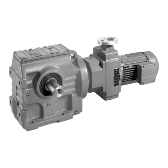
- Page 1 Gearmotors \ Industrial Gear Units \ Drive Electronics \ Drive Automation \ Services Explosion-Proof ® VARIMOT Variable Speed Gear Units and Accessories Edition 11/2006 perating nstructions 11529016 / EN...
- Page 2 SEW-EURODRIVE – Driving the world...
-
Page 3: Table Of Contents
Contents 1 Important Information about the Operating Instructions ......4 Explanation of symbols ................6 2 Safety Notes ...................... 7 ® Safety notes for the use of VARIMOT ............. 7 ® 3 VARIMOT in Explosion-Proof Version ............8 Unit design ....................8 Unit designation .................. -
Page 4: Important Information About The Operating Instructions
EC Directive 94/9/EC and the EC Directive for Machinery 98/37/EC. Gear unit loads other than those specified and areas of application other than industrial and commercial systems can only be used after consultation with SEW-EURODRIVE. Any application other than those mentioned is considered non-intended use. - Page 5 SEW-EURODRIVE GmbH & Co KG assumes no liability for injury to persons or damage to equipment or property resulting from non-observance of these operating instructions. In such cases, any liability for defects is excluded.
-
Page 6: Explanation Of Symbols
Important Information about the Operating Instructions Explanation of symbols Explanation of symbols The operating instructions contain important information that deals with general and operational safety. This information is emphasized in particular with the following symbols. Electrical hazard Possible consequences: Severe or fatal injuries. Hazard Possible consequences: Severe or fatal injuries. -
Page 7: Safety Notes
Safety Notes Safety notes for the use of VARIMOT® Safety Notes ® Safety notes for the use of VARIMOT The following safety notes apply to variable speed gear units. When using variable speed gearmotors, also refer to the safety notes for gear units and motors in the relevant operating instructions. -
Page 8: Varimot ® In Explosion-Proof Version
VARIMOT® in Explosion-Proof Version Unit design ® VARIMOT in Explosion-Proof Version Unit design [10] 52018AXX ® Fig. 1: VARIMOT in explosion-proof version Complete output shaft Plate Adjusting plate Housing cover Drive disk Needle bearing Housing with tapped hole Complete hollow shaft [10] Friction ring ®... -
Page 9: Unit Designation
VARIMOT® in Explosion-Proof Version Unit designation Unit designation The following diagram shows the type code structure: DV 26B WEX II2G eDT 90L 4 TF Temperature sensor Number of motor poles Motor size Motor series Explosion-proof version according to ATEX 100a Speed monitor ®... -
Page 10: Nameplate
VARIMOT® in Explosion-Proof Version Nameplate Nameplate Example Bruchsal / Germany DF36/A/IGEX/II2G 01.1151703702.0001.06 e r/min 159/798 1440 a r/min 84/38 a Nm 104.242 Bedienungsanleitung muss beachtet werden Zum Einbau in Komplettantrieb RX77 D36/IGEX/II2G eDV112M4/C II2G / T3 Lagerfett synth. KHC2R Made in Germany 150 881 4.10 60417AXX Fig. -
Page 11: Overview Of Mounting Options
VARIMOT® in Explosion-Proof Version Overview of mounting options Overview of mounting options 52019AXX Fig. 3: Overview of mounting options Adjustment device with free shaft end NV Adjustment device with handwheel and position indication HS Adjustment device with handwheel (standard version) Indicator scale Voltage encoder IGEX ®... -
Page 12: Installation
II, category 2G (explosive gas atmosphere). These units are intended for use in zones 1 and 2. • A standard feature of the SEW-EURODRIVE explosion-proof variable speed gear ® units of the VARIMOT series is a tapped hole for installing a voltage encoder. -
Page 13: Permitted Overhung Loads Without Primary Gear Unit
Figure 1. If force is applied overhung loads to areas other than the center of the shaft end, consult SEW-EURODRIVE for permitted lateral forces. 50248AXX Fig. 4: Definition of force application of overhung loads [N] = permitted overhung load point of application at mid-point of shaft extension. - Page 14 Installation Permitted overhung loads without primary gear unit VARIMOT ® D16 2500 2000 1500 DT71D4 DT80K4 DT80N4 1000 1200 1500 1800 n [1/min] 51908AXX VARIMOT ® D26 4000 3500 3000 2500 2000 DV100M4 1500 DT90L4 DT90S4 1000 1200 1500 1800 n [1/min] 51909AXX ®...
- Page 15 Installation Permitted overhung loads without primary gear unit VARIMOT ® D36 6000 5000 4000 3000 2000 DV100L4 DV112M4 1000 DV132S4 1200 1800 1500 n [1/min] 51911AXX VARIMOT ® D46 10000 9000 8000 7000 6000 5000 4000 3000 DV132M4 2000 DV132ML4 DV160M4 1000 1000...
-
Page 16: Before You Begin
Installation Before you begin Before you begin The drive • The information on the nameplate of the drive matches the approved on-site explo- may only be sion application range (equipment group, category, zone, temperature class or max- installed if imum surface temperature). •... -
Page 17: Installation
Installation Installation Installation • The variable speed gearmotor may only be mounted or installed on a level , vibra- tion-damping and torsionally rigid support structure. Do not tighten housing legs and mounting flanges against each other. ® • VARIMOT version HS (handwheel with position indication) must be mounted so that the adjusting spindle is horizontal;... - Page 18 Installation Installation Required tools/ • Set of wrenches resources • Mounting device • Compensation elements (shims, spacing rings), if necessary • Mounting materials for output components Installation tolerances Shaft end Flanges Diameter tolerance in accordance with DIN 748 Centering shoulder tolerance in accordance with •...
-
Page 19: Gear Units With Solid Shafts
Installation Gear units with solid shafts Gear units with solid shafts Only use ATEX approved input and output components. Input and output elements such as belt pulleys, couplings, etc. must have protec- tion against contact. • Never drive belt pulleys, couplings, pinions, etc. onto the shaft end by hitting them with a hammer (this will cause damage to bearings, housing and the shaft). - Page 20 Installation Gear units with solid shafts The following illustration shows the correct mounting arrangement (B) of a gear wheel or chain sprocket for avoiding impermissibly high overhung loads. 52021AXX Fig. 6: Correct mounting arrangement of a gear or sprocket wheel Incorrect Correct •...
-
Page 21: Startup
Startup Installation and setup of optional equipment Startup Installation and setup of optional equipment Speed monitoring Category 2G variable speed gear units may only be started up with speed moni- toring. ® Standard version The standard version of the explosion-proof VARIMOT variable speed gear unit fea- ®... - Page 22 Startup Installation and setup of optional equipment Speed monitor in WEXA/WEX version: Manufacturer: Pepperl + Fuchs, Mannheim Type: KFU8-UFC-Ex1.D Auxiliary power: DC 20 - 90 V / AC 48 - 253 V ATEX certification number: TÜV 99 ATEX 1471 All installation and setting notes given below refer to the speed monitor or voltage encoder in WEXA/WEX version.
- Page 23 Startup Installation and setup of optional equipment Installation and adjustment of the WEXA/WEX speed monitor The speed monitor must be located outside the potentially explosive atmosphere. 1. Read the operating instructions of the speed monitor manufacturer before you begin with the installation. BU 2- DF16 BN 1+...
- Page 24 Startup Installation and setup of optional equipment Front side of the speed monitor 50999AXX Fig. 9: WEXA/WEX speed monitor Front side of the speed monitor: LED in CHK 1 For indicating input pulses (flashes yellow), input interference (blinks red), (yellow/red) and unit malfunction (continuously red) LED PWR (green) For indicating the supply voltage...
- Page 25 Startup Installation and setup of optional equipment Setting the switching Variable speed Motor Motor Switching Switching Pulses per frequency via gear unit type pole no. frequency speed frequency revolution parameters [Hz] [rpm] [Hz] 30.0 19.4 15.0 D / DF16D / DF16B 37.5 24.0...
- Page 26 Startup Installation and setup of optional equipment Installation and adjustment of other speed monitors If other speed monitors are used, they must feature an intrinsically safe sensor input (identification color: blue) for evaluation of sensors according to DIN 19234 (NAMUR) and be approved for use of this sensor in potentially explosive atmo- spheres.
- Page 27 Startup Installation and setup of optional equipment Installing/ 1. Rotate the output shaft of the variable speed gear unit until the machined casting connecting the surface of the friction ring carrier can be seen through the tapped hole in the gear unit IGEX voltage housing.
- Page 28 Startup Installation and setup of optional equipment Changing If no circuit state change occurs at the voltage encoder with rotating shaft of the variable switching speed gear unit operating at switching interval X, then the switching interval can be interval X changed.
- Page 29 Startup Installation and setup of optional equipment Connection/ 1. Connect the unit according to the wiring diagram adjustment This wiring diagram applies only to digital indicator units type HDA 4110-50 by Dr. Horn in combination with speed monitors type KFU8-UFC-Ex1.D by Pepperl + Fuchs.
- Page 30 Startup Installation and setup of optional equipment Time basis [s] Pulse multiplie r 0.01 0.001 Pulse control Decimal point setting Input sensitivity 03708AEN Fig. 13: Adjusting the digital remote speed indicator Adjusting the digital remote • Indicating accuracy: +/–1 of last digit speed indicator •...
- Page 31 Startup Installation and setup of optional equipment Reference data of digital remote speed indicator ® Reference speed VARIMOT [rpm] Pulses/ ® Type/size VARIMOT revolution 4-pole 6-pole 8-pole D 16 1690 1065 D 26 1825 1200 D 36 1675 1080 D 46 1610 1073 Calculation examples for digital remote speed indicator...
-
Page 32: Inspection And Maintenance
Inspection and Maintenance Inspection and maintenance intervals Inspection and Maintenance Strict adherence to the inspection and maintenance intervals is absolutely neces- sary to ensure safe working conditions and explosion protection. • Strictly observe the safety notes in the individual sections. •... -
Page 33: Before You Begin
Inspection and Maintenance Before you begin Before you begin Required • Set of wrenches tools/resources • Hammer • Drift or punch drift • Snap ring, mounting press Checking torsional play The torsional play of the output shaft is increased through wear of the friction ring. The torsional play can be checked as follows: 1. -
Page 34: Checking The Friction Ring
Inspection and Maintenance Checking the friction ring Checking the friction ring [10] 52024AXX Fig. 14: Checking/replacing friction ring [1] Shaft Housing [2] Retaining screws Hollow shaft [7] Needle roller bearing [10] Friction ring [3] [16] [6] [5] 52025AXX Fig. 15: Checking/replacing friction ring [3] Flange Drive disk [4] Adjusting plate... -
Page 35: Replacing The Friction Ring
Inspection and Maintenance Replacing the friction ring 1. Loosen all retaining screws [2] 2. Disconnect drive between housing cover [5] and housing [8] 3. Check friction ring • If chamfers are visible: friction ring is OK • If friction ring is damaged or chamfer is ground off: replace friction ring (see "Replacing the friction ring") 51790AXX Fig. -
Page 36: Measuring The Temperature Of The Anti-Friction Bearing
Inspection and Maintenance Measuring the temperature of the anti-friction bearing Measuring the temperature of the anti-friction bearing To ensure safe working conditions and explosion protection, it is necessary that the temperature of the anti-friction bearing does not exceed 100 °C (212 °F) at test points T1 and T2 (see following figure). -
Page 37: Completing The Inspection/Maintenance Process
Inspection and Maintenance Completing the inspection/maintenance process Completing the inspection/maintenance process • Ensure that the variable speed drive is assembled correctly and all openings have been plugged after service and maintenance work. • Perform safety and function tests following all maintenance and repair work. ®... -
Page 38: Operation And Service
Operation and Service Customer service Operation and Service • To eliminate malfunctions, the gear unit and additional equipment must be deactivated. Prevent the drive unit from starting up unintentionally (for example, by locking the keyswitch or removing the fuses from the power supply). -
Page 39: Wexa/Wex Speed Monitor
Operation and Service WEXA/WEX speed monitor WEXA/WEX speed monitor Problem Possible cause Solution Check voltage supply of voltage encoder using the evaluation electronics With correct voltage supply: Voltage encoder is Voltage encoder is not properly • Consult manufacturer's documentation not functioning connected •... -
Page 40: Declaration Of Conformity
EN1127-1 SEW-EURODRIVE hinterlegt die gemäß 94/9/EG Anhang VIII geforderten Unterlagen bei benannter Stelle: FSA GmbH, EU-Kennnummer 0588 SEW-EURODRIVE will archive the documents required according to 94/9/EG at the following location: FSA GmbH, EU Code 0588 SEW-EURODRIVE GmbH & Co Bruchsal, den 09.08.2000... -
Page 41: Variable Speed Gear Units Category 3G And 3D, Varimot
EN1127-1 Applicable standard: EN1127-1 SEW-EURODRIVE hält die gemäß 94/9/EG geforderten Unterlagen zur Einsicht bereit. SEW-EURODRIVE will make available the documents required according to 94/9/EG for reference purposes. SEW-EURODRIVE GmbH & Co Bruchsal, den 09.08.2000 Vertriebsleitung / Deutschland Ort und Datum der Ausstellung... -
Page 42: Index
Index Index Anti-friction bearing greases .......16 Optional equipment ..........7 Overview of mounting options ......11 Checking the friction ring ........34 Checking torsional play ........33 Permitted overhung loads without primary gear unit ............. 13 Completing the inspection/maintenance process ...............37 Customer service ..........38 Remote speed indicator ........ - Page 43 Address List Address List Germany Headquarters Bruchsal SEW-EURODRIVE GmbH & Co KG Tel. +49 7251 75-0 Production Ernst-Blickle-Straße 42 Fax +49 7251 75-1970 Sales D-76646 Bruchsal http://www.sew-eurodrive.de P.O. Box sew@sew-eurodrive.de Postfach 3023 • D-76642 Bruchsal Service Central SEW-EURODRIVE GmbH & Co KG Tel.
- Page 44 Electro-Services Tel. +237 4322-99 Rue Drouot Akwa Fax +237 4277-03 B.P. 2024 Douala Canada Assembly Toronto SEW-EURODRIVE CO. OF CANADA LTD. Tel. +1 905 791-1553 Sales 210 Walker Drive Fax +1 905 791-2999 Service Bramalea, Ontario L6T3W1 http://www.sew-eurodrive.ca l.reynolds@sew-eurodrive.ca Vancouver SEW-EURODRIVE CO.
- Page 45 Address List China Production Tianjin SEW-EURODRIVE (Tianjin) Co., Ltd. Tel. +86 22 25322612 Assembly No. 46, 7th Avenue, TEDA Fax +86 22 25322611 Sales Tianjin 300457 gm-tianjin@sew-eurodrive.cn Service http://www.sew-eurodrive.com.cn Assembly Suzhou SEW-EURODRIVE (Suzhou) Co., Ltd. Tel. +86 512 62581781 Sales...
- Page 46 Tel. +972 3 5599511 Ahofer Str 34B / 228 Fax +972 3 5599512 58858 Holon lirazhandasa@barak-online.net Italy Assembly Milano SEW-EURODRIVE di R. Blickle & Co.s.a.s. Tel. +39 02 96 9801 Sales Via Bernini,14 Fax +39 02 96 799781 Service I-20020 Solaro (Milano) http://www.sew-eurodrive.it sewit@sew-eurodrive.it...
- Page 47 No. 95, Jalan Seroja 39, Taman Johor Jaya Fax +60 7 3541404 Service 81000 Johor Bahru, Johor sales@sew-eurodrive.com.my West Malaysia Mexico Assembly Queretaro SEW-EURODRIVE MEXIKO SA DE CV Tel. +52 442 1030-300 Sales SEM-981118-M93 Fax +52 442 1030-301 Service Tequisquiapan No. 102 http://www.sew-eurodrive.com.mx Parque Industrail Queretaro scmexico@seweurodrive.com.mx...
- Page 48 Address List Poland Assembly Lodz SEW-EURODRIVE Polska Sp.z.o.o. Tel. +48 42 67710-90 Sales ul. Techniczna 5 Fax +48 42 67710-99 Service PL-92-518 Lodz http://www.sew-eurodrive.pl sew@sew-eurodrive.pl Portugal Assembly Coimbra SEW-EURODRIVE, LDA. Tel. +351 231 20 9670 Sales Apartado 15 Fax +351 231 20 3685...
- Page 49 Address List South Africa Assembly Johannesburg SEW-EURODRIVE (PROPRIETARY) LIMITED Tel. +27 11 248-7000 Sales Eurodrive House Fax +27 11 494-3104 Service Cnr. Adcock Ingram and Aerodrome Roads http://www.sew.co.za Aeroton Ext. 2 dross@sew.co.za Johannesburg 2013 P.O.Box 90004 Bertsham 2013 Capetown SEW-EURODRIVE (PROPRIETARY) LIMITED Tel.
- Page 50 Dallas, Texas 75237 csdallas@seweurodrive.com Additional addresses for service in the USA provided on request! Venezuela Assembly Valencia SEW-EURODRIVE Venezuela S.A. Tel. +58 241 832-9804 Sales Av. Norte Sur No. 3, Galpon 84-319 Fax +58 241 838-6275 Service Zona Industrial Municipal Norte http://www.sew-eurodrive.com.ve...
- Page 51 SEW-EURODRIVE – Driving the world...
- Page 52 Internet, available Anywhere. today. around the clock. SEW-EURODRIVE GmbH & Co KG P.O. Box 3023 · D-76642 Bruchsal / Germany Phone +49 7251 75-0 · Fax +49 7251 75-1970 sew@sew-eurodrive.com → www.sew-eurodrive.com...
Need help?
Do you have a question about the Varimot 16-46 Series and is the answer not in the manual?
Questions and answers