SEW-Eurodrive MOVIDRIVE MDX61B System Manual
Hide thumbs
Also See for MOVIDRIVE MDX61B:
- System manual (760 pages) ,
- Operating instructions manual (380 pages) ,
- Manual (156 pages)

Related Manuals for SEW-Eurodrive MOVIDRIVE MDX61B


Summary of Contents for SEW-Eurodrive MOVIDRIVE MDX61B
- Page 1 Drive Technology \ Drive Automation \ System Integration \ Services ® MOVIDRIVE MDX60B / 61B System Manual Edition 06/2008 11697415 / EN...
- Page 2 Color Code System Color code system for catalogs and system manuals Our catalogs and system manuals are identified by a color code system at the back to make it easier to work with these publications. The short designation of the publication is indicated as well.
- Page 3 1 System Description....................7 2 Technical Data and Dimension Drawings ............33 3 Parameters......................147 P6.. P60. P600 4 Project Planning ....................251 5 Serial Communication ..................351 6 Structure of the Safety Notes................352 7 Safety Notes ....................... 353 8 Unit Design ......................
-
Page 4: Table Of Contents
1 System Description....................7 ® System Overview MOVIDRIVE MDX60B/61B ............7 Functions / features ....................18 Additional functions of the application version ............20 ® Application modules for MOVIDRIVE MDX61B ............24 ® MOVITOOLS operating software ................32 2 Technical Data and Dimension Sheets .............. 33 CE-marking, UL approval and C-Tick ................ - Page 5 3 Parameters......................147 Menu structure DBG60B ..................147 Overview of parameters ................... 148 Explanation of the parameters ................. 157 Duty types ........................ 239 4 Project Planning ....................251 Schematic procedure ....................251 Control characteristics....................252 Description of applications ..................253 Basic recommendations for motor selection ............
- Page 6 9 Installation ......................367 Installation instructions for basic unit ............... 367 Removing/installing the keypad ................374 Removing/installing the front cover ................375 UL-compliant installation ..................377 Shield clamps......................379 Touch guard for power terminals ................382 Wiring diagrams for basic unit.................. 385 Assignment of braking resistors, chokes and filters ..........
-
Page 7: System Description
System Description System Overview MOVIDRIVE® MDX60B/61B System Description ® System Overview MOVIDRIVE MDX60B/61B Power components 3 x AC 380...500 V 3 x AC 200...240 V Line filter option Line choke option Regenerative power supply unit option ® ® MOVIDRIVE MOVIDRIVE ®... - Page 8 System Description System Overview MOVIDRIVE® MDX60B/61B Encoder and communication options MDX60/61B application version for using plus® "Electronic cam", "Internal synchronous operation" MDX60/61B standard version with IPOS as standard or the application modules. MASTER DBG60B keypad option MOVITOOLS ® operating software System bus (SBus) Encoder options...
- Page 9 System Description System Overview MOVIDRIVE® MDX60B/61B Fieldbus options DFC 11B DFD 11B DFI 21B DFP 21B DFI 11B DFE 11B DFE 12B DFE 13B DFE 24B DFE 32B DFE 33B DFE33B MODULE STATUS NETWORK STATUS ETHERNET/IP 63227AXX System Manual – MOVIDRIVE® MDX60B/61B Inverter...
- Page 10 System Description System Overview MOVIDRIVE® MDX60B/61B Control options MOVI-PLC ® DHP 11B OST 11B DHE 41B DHF 41B 63062AXX System Manual – MOVIDRIVE® MDX60B/61B Inverter...
- Page 11 System Description System Overview MOVIDRIVE® MDX60B/61B Safety options DFS 11B DFS 12B DFS 21B DFS 22B DCS 21B DCS 31B 63061AXX System Manual – MOVIDRIVE® MDX60B/61B Inverter...
- Page 12 System Description System Overview MOVIDRIVE® MDX60B/61B ® General MOVIDRIVE MDX60/61B is the new generation of drive inverters from SEW. The new ® description MOVIDRIVE B series inverters feature a modular design, provide enhanced functions in the lower power range, more basic functions and greater overload capacity. AC drives with the latest digital inverter technology can now be used without restrictions in the 0.55 to 160 kW power range.
- Page 13 System Description System Overview MOVIDRIVE® MDX60B/61B ® Modular unit The option-capable MOVIDRIVE MDX61B units have the following option slots: concept Size 0 (0005 ... 0014) → 2 option slots • – 1 option slot for encoder connection – 1 option slot for a communication option Sizes 1 ...
- Page 14 System Description System Overview MOVIDRIVE® MDX60B/61B Required option Option slot Encoder option Asynchronous AC motor with encoder feedback ® (HIPERFACE , sin/cos, TTL) ® HIPERFACE encoder card DEH11B Asynchronous or synchronous ® servomotor with HIPERFACE encoder SSI encoder interface Absolute encoder card DEH21B Synchronous servomotor with Resolver card type DER11B resolver...
- Page 15 System Description System Overview MOVIDRIVE® MDX60B/61B Control mode The VFC (Voltage Flux Control) and CFC (Current Flux Control)/SERVO control modes ® are features of MOVIDRIVE MDX60B/61B inverters. The continuous calculation of the complete motor model forms the basis for both control modes. VFC (Voltage Flux Control) control mode CFC (Current Flux Control)/SERVO control mode...
- Page 16 System Description System Overview MOVIDRIVE® MDX60B/61B The units at a glance ® MDX60/61B for 3 × AC 380 ... 500 V supply voltage (AC 400/500 V units): MOVIDRIVE ® Recommended motor power (VFC) Contin. output current MOVIDRIVE type Size MDX60B MDX61B (techn.
- Page 17 System Description System Overview MOVIDRIVE® MDX60B/61B Block circuit The following block circuit diagram shows the basic structure and theory of operation of ® diagram MOVIDRIVE MDX60B/61B inverters. Input protection Rectifier Inverter switch Brake link chopper Power Motor supply Control signals Supply Current X10:...
-
Page 18: Functions / Features
System Description Functions / features Functions / features Unit properties • Wide voltage range – 400/500 V units for the voltage range 3 × AC 380 ... 500 V – 230 V units for the voltage range 3 × AC 200 ... 240 V •... - Page 19 System Description Functions / features • Speed monitoring and monitoring of the motor and regenerative limit power • Programmable signal range monitoring (speed, current, maximum current) • Memory for displaying x/t diagrams using SCOPE process data visualization four channels (8 channels, real-time capable) •...
-
Page 20: Additional Functions Of The Application Version
System Description Additional functions of the application version ® Standards / • UL, cUL, C-Tick approval. The MOVIDRIVE MDR60A1320-503-00 unit does not certificates have UL or cUL or C-Tick approval. The GOST-R certificate (Russia) is approved for ® the MOVIDRIVE range of units. - Page 21 System Description Additional functions of the application version Motors and Use the following motor types: encoders ® • For operation with MOVIDRIVE MDX61B...-4-0T: – CT/CV asynchronous servomotor, high-resolution sin/cos encoder installed as ® standard or HIPERFACE encoder. – DT/DV/D series AC motors with incremental encoder option, preferably high- ®...
- Page 22 System Description Additional functions of the application version ® Internal synchro- You can always use the MOVIDRIVE range of units with "internal synchronous opera- nous operation tion" whenever a group of motors has to be operated at a synchronous angle in relation to one another or with an adjustable proportional ratio (electronic gear).
- Page 23 System Description Additional functions of the application version Example The figure below shows a typical application for the "internal synchronous operation." Extruder material must be cut to length. The saw receives a start signal and synchronizes with the material. During the sawing process, the saw moves synchronously with the material.
-
Page 24: Application Modules For Movidrive® Mdx61B
System Description Application modules for MOVIDRIVE® MDX61B ® Application modules for MOVIDRIVE MDX61B The application The drive application often involves more than just adjusting the speed of a motor. The inverter often has to control motion sequences and take on typical PLC tasks. More and more complex drive applications have to be solved, without this resulting in lengthy project planning and startup. - Page 25 System Description Application modules for MOVIDRIVE® MDX61B The following illustration shows an example of how the various SEW application modules are used in a block warehouse. 04008AXX Figure 4: Use in a high-bay warehouse 1. Hoist: Table positioning 2. Travel axis: Absolute value or bus positioning 3.
- Page 26 System Description Application modules for MOVIDRIVE® MDX61B Positioning The application modules for the "Positioning" application are suited to all applications where target positions are specified and movement then takes place to those positions. Movement can either be linear or rotatory. Such sequences of motions include trolleys, hoists, gantries, rotary tables, swiveling devices and storage and retrieval units for high-bay warehouses.
- Page 27 System Description Application modules for MOVIDRIVE® MDX61B • Straightforward connection to the machine control. • Guided startup and diagnostics. There are 3 operating modes for controlling the machine: • Jog mode: The machine can be moved manually. • Reference travel: The machine zero is determined automatically for incremental position measurement.
- Page 28 System Description Application modules for MOVIDRIVE® MDX61B Rotational • Modulo positioning positioning A large number of movements have to be controlled in automated conveyor and logistics applications to transport the material. Linear movements in the form of trolleys or hoists, and rotary movements via rotary tables play an important role in these applications.
- Page 29 System Description Application modules for MOVIDRIVE® MDX61B Winding • Center winder The "Central winder" application module is suitable for applications in which endless material, such as paper, plastic, fabrics, sheet metal or wire, must be wound, unwound or rewound continuously. Control takes place either via the binary inputs of the inverter or using the virtual terminals (fieldbus, system bus).
- Page 30 System Description Application modules for MOVIDRIVE® MDX61B Controlling • Flying saw The "Flying saw" application module is suited to applications in which endless material has to be cut, sawn or pressed, for example in diagonal saws or flying punches. This application module is used to control the sequence of motion according to specific values.
- Page 31 System Description Application modules for MOVIDRIVE® MDX61B Four operating modes are available for controlling the application: • Jog mode • Reference travel • Positioning mode • Synchronous operation – The electrical connection of the master/slave can be made using the X14 encoder connection or an SBus connection.
-
Page 32: Movitools® Operating Software
System Description MOVITOOLS® operating software ® MOVITOOLS operating software ® plus® Description MOVITOOLS is a program package comprising SHELL, SCOPE and the IPOS ® ® Compiler. MOVITOOLS can be used for the MOVIDRIVE MDX60B/61B and ® MOVIDRIVE compact range of units. •... -
Page 33: Technical Data And Dimension Sheets
Technical Data and Dimension Sheets CE-marking, UL approval and C-Tick Technical Data and Dimension Sheets CE-marking, UL approval and C-Tick CE marking • Low voltage directive ® MOVIDRIVE MDX60B/61B inverters comply with the regulations of the Low Voltage Directive 2006/95/EC. •... -
Page 34: General Technical Data
Technical Data and Dimension Sheets General technical data General technical data ® The following table lists the technical data applicable to all MOVIDRIVE MDX60B/61B inverters, regardless of their type, version, size and performance. ® MOVIDRIVE MDX60B/61B All sizes Interference resistance Complies with EN 61800-3 Interference emission with Sizes 0 to 6 meet EN 61800-3... - Page 35 Technical Data and Dimension Sheets General technical data ® MOVIDRIVE MDX60B/61B series, size 0 51485AXX ® Figure 6: MOVIDRIVE MDX60/61B series, size 0 ® MOVIDRIVE MDX61B series, sizes 1 to 6 52159AXX ® Figure 7: MOVIDRIVE MDX61B series, sizes 1 to 6 System Manual –...
-
Page 36: Movidrive® Mdx60/61B
Technical Data and Dimension Sheets MOVIDRIVE® MDX60/61B...-5_3 (AC 400/500 V units) ® MOVIDRIVE MDX60/61B...-5_3 (AC 400/500 V units) Size 0 ® MOVIDRIVE MDX60/61B 0005-5A3-4-0_ 0008-5A3-4-0_ 0011-5A3-4-0_ 0014-5A3-4-0_ Size INPUT 3 × AC 380 V -500 V Rated supply voltage (to EN 50160) supply 50 Hz ... - Page 37 Technical Data and Dimension Sheets MOVIDRIVE® MDX60/61B...-5_3 (AC 400/500 V units) MDX61B standard version 0005-5A3-4-00 0008-5A3-4-00 0011-5A3-4-00 0014-5A3-4-00 Design with coated printed circuit boards 0005-5A3-4-00/L 0008-5A3-4-00/L 0011-5A3-4-00/L 0014-5A3-4-00/L 827 722 2 827 723 0 827 724 9 827 725 7 Part number 828 947 6 828 948 4...
- Page 38 Technical Data and Dimension Sheets MOVIDRIVE® MDX60/61B...-5_3 (AC 400/500 V units) Size 1 (AC 400/500 V units) ® MOVIDRIVE MDX61B 0015-5A3-4-0_ 0022-5A3-4-0_ 0030-5A3-4-0_ 0040-5A3-4-0_ INPUT 3 × AC 380 V - 500 V Rated supply voltage (to EN 50160) supply 50 Hz ...
- Page 39 Technical Data and Dimension Sheets MOVIDRIVE® MDX60/61B...-5_3 (AC 400/500 V units) Sizes 2S, 2 (AC 400/500 V units) ® MOVIDRIVE MDX61B 0055-5A3-4-0_ 0075-5A3-4-0_ 0110-5A3-4-0_ Size INPUT 3 × AC 380 V - 500 V Rated supply voltage (to EN 50160) supply 50 Hz ...
- Page 40 Technical Data and Dimension Sheets MOVIDRIVE® MDX60/61B...-5_3 (AC 400/500 V units) Size 3 (AC 400/500 V units) ® MOVIDRIVE MDX61B 0150-503-4-0_ 0220-503-4-0_ 0300-503-4-0_ INPUT 3 × AC 380 V - 500 V Rated supply voltage (to EN 50160) supply 50 Hz ... 60 Hz ±5 % Supply frequency supply Rated supply current...
- Page 41 Technical Data and Dimension Sheets MOVIDRIVE® MDX60/61B...-5_3 (AC 400/500 V units) Size 4 (AC 400/500 V units) ® MOVIDRIVE MDX61B 0370-503-4-0_ 0450-503-4-0_ INPUT 3 × AC 380 V - 500 V Rated supply voltage (to EN 50160) supply 50 Hz ... 60 Hz ±5 % Supply frequency supply Rated supply current...
- Page 42 Technical Data and Dimension Sheets MOVIDRIVE® MDX60/61B...-5_3 (AC 400/500 V units) Size 5 (AC 400/500 V units) ® MOVIDRIVE MDX61B 0550-503-4-0_ 0750-503-4-0_ INPUT 3 × AC 380 V - 500 V Rated supply voltage (to EN 50160) supply 50 Hz ... 60 Hz ±5 % Supply frequency supply Rated supply current...
- Page 43 Technical Data and Dimension Sheets MOVIDRIVE® MDX60/61B...-5_3 (AC 400/500 V units) Size 6 (AC 400/500 V units) ® MOVIDRIVE MDX61B 0900-503-4-0_ 1100-503-4-0_ 1320-503-4-0_ INPUT 3 × AC 380 V - 500 V Rated supply voltage (to EN 50160) supply 50 Hz ... 60 Hz ±5 % Supply frequency supply Rated supply current...
-
Page 44: Movidrive® Mdx61B
Technical Data and Dimension Sheets MOVIDRIVE® MDX61B...-2_3 (AC 230 V units) ® MOVIDRIVE MDX61B...-2_3 (AC 230 V units) Size 1 (AC 230 V units) ® MOVIDRIVE MDX61B 0015-2A3-4-0_ 0022-2A3-4-0_ 0037-2A3-4-0_ INPUT 3 × AC 200 V - 240 V Rated supply voltage (to EN 50160) supply 50 Hz ... - Page 45 Technical Data and Dimension Sheets MOVIDRIVE® MDX61B...-2_3 (AC 230 V units) Size 2 (AC 230 V units) ® MOVIDRIVE MDX61B 0055-2A3-4-0_ 0075-2A3-4-0_ INPUT 3 × AC 200 V - 240 V Rated supply voltage (to EN 50160) supply 50 Hz ... 60 Hz ± 5 % Supply frequency supply Rated supply current...
- Page 46 Technical Data and Dimension Sheets MOVIDRIVE® MDX61B...-2_3 (AC 230 V units) Size 3 (AC 230 V units) ® MOVIDRIVE MDX61B 0110-203-4-0_ 0150-203-4-0_ INPUT 3 × AC 200 V - 240 V Rated supply voltage (to EN 50160) supply 50 Hz ... 60 Hz ± 5 % Supply frequency supply Rated supply current...
- Page 47 Technical Data and Dimension Sheets MOVIDRIVE® MDX61B...-2_3 (AC 230 V units) Size 4 (AC 230 V units) ® MOVIDRIVE MDX61B 0220-203-4-0_ 0300-203-4-0_ INPUT 3 × AC 200 V - 240 V Rated supply voltage (to EN 50160)V supply 50 Hz ... 60 Hz ± 5 % Supply frequency supply Rated supply current...
-
Page 48: Movidrive® Mdx60/61B Electronics Data
Technical Data and Dimension Sheets MOVIDRIVE® MDX60/61B electronics data ® MOVIDRIVE MDX60/61B electronics data ® MOVIDRIVE MDX60/61B General electronics data Voltage supply X11:1 REF1: DC+10 V +5 % / –0 %, I = DC 3 mA Reference voltages for setpoint potentiometer REF2: DC–10 V +0 % / –5 %, I = DC 3 mA for setpoint input... - Page 49 Technical Data and Dimension Sheets MOVIDRIVE® MDX60/61B electronics data ® MOVIDRIVE MDX60/61B General electronics data Safety contact X17:1 DGND: Reference potential for X17:3 X17:2 VO24: : V = DC 24 V, only to supply X17:4 of the same unit; it cannot be used to supply other units.
-
Page 50: Movidrive® Mdx60B Dimension Sheets
Technical Data and Dimension Sheets MOVIDRIVE® MDX60B dimension sheets ® MOVIDRIVE MDX60B dimension sheets Size 0S 249 (9.8) 6 (0.24) 260 (10.2) 45 (1.8) 53019CXX Figure 8: Dimensions for MDX60B size 0S, dimensions in mm (in) Size 0S with braking resistor installed 249 (9.8) 6 (0.24) - Page 51 Technical Data and Dimension Sheets MOVIDRIVE® MDX60B dimension sheets Size 0M 249 (9.8) 6 (0.24) 260 (10.2) 67.5 (2.66) 53022CXX Figure 10: Dimensions for MDX60B size 0M, dimensions in mm (in) Size 0M with braking resistor 6 (0.24) 249 (9.8) 260 (10.2) 67.5 (2.66) 94 (3.7)
-
Page 52: Movidrive® Mdx61B Dimension Sheets
Technical Data and Dimension Sheets MOVIDRIVE® MDX61B dimension sheets ® MOVIDRIVE MDX61B dimension sheets NOTE ® For MOVIDRIVE MDX61B size 0, installing a braking resistor does not affect the ® dimensions. Therefore, MOVIDRIVE MDX61B size 0 dimensions are displayed without an installed braking resistor. Size 0S 249 (9.8) 6 (0.24) - Page 53 Technical Data and Dimension Sheets MOVIDRIVE® MDX61B dimension sheets Size 0M 6 (0.24) 249 (9.8) 67.5 (2.66) 260 (10.2) 95 (3.7) 51378CXX Figure 13: Dimensions for MDX61B size 0M, dimensions in mm (in) System Manual – MOVIDRIVE® MDX60B/61B Inverter...
- Page 54 Technical Data and Dimension Sheets MOVIDRIVE® MDX61B dimension sheets Size 1 234 (9.21) 105 (4.13) 6 (0.24) 85 (3.3) 6 (0.24) 52274CXX Figure 14: Dimensions for MDX61B size 1, dimensions in mm (in) System Manual – MOVIDRIVE® MDX60B/61B Inverter...
- Page 55 Technical Data and Dimension Sheets MOVIDRIVE® MDX61B dimension sheets Size 2S 105 (4.13) 294 (11.6) 70 (2.8) 7 (0.28) 52273CXX Figure 15: Dimensions for MDX61B size 2S, dimensions in mm (in) System Manual – MOVIDRIVE® MDX60B/61B Inverter...
- Page 56 Technical Data and Dimension Sheets MOVIDRIVE® MDX61B dimension sheets Size 2 285 (11.2) 130 (5.12) 105 (4.13) 6,5 (0.26) 124.5 (4.9) 52276CXX Figure 16: Dimensions for MDX61B size 2, dimensions in mm (in) System Manual – MOVIDRIVE® MDX60B/61B Inverter...
- Page 57 Technical Data and Dimension Sheets MOVIDRIVE® MDX61B dimension sheets Size 3 308 (12.1) 200 (7.87) 105 (4.13) 2 (0.08) 7 (0.3) 52315CXX Figure 17: Dimensions for MDX61B size 3, dimensions in mm (in) System Manual – MOVIDRIVE® MDX60B/61B Inverter...
- Page 58 Technical Data and Dimension Sheets MOVIDRIVE® MDX61B dimension sheets Size 4 307 (12.1) 280 (11.0) 2 (0.08) 140 (5.51) 7 (0.3) 52277CXX Figure 18: Dimensions for MDX61B size 4, dimensions in mm (in) System Manual – MOVIDRIVE® MDX60B/61B Inverter...
- Page 59 Technical Data and Dimension Sheets MOVIDRIVE® MDX61B dimension sheets Size 5 280 (11.0) 330 (13.0) 140 (5.51) 2 (0.08) 7 (0.3) 52278CXX Figure 19: Dimensions for MDX61B size 5, dimensions in mm (in) System Manual – MOVIDRIVE® MDX60B/61B Inverter...
- Page 60 Technical Data and Dimension Sheets MOVIDRIVE® MDX61B dimension sheets Size 6 382 (15.0) 2 (0.08) 140 (5.51) 11 (0.43) 9 (0.4) 294 (11.6) 318 (12.5) 58389CXX Figure 20: Dimensions for MDX61B size 6, dimensions in mm (in) System Manual – MOVIDRIVE® MDX60B/61B Inverter...
-
Page 61: Movidrive® Mdr60A Regenerative Power Supply Units
Technical Data and Dimension Sheets MOVIDRIVE® MDR60A regenerative power supply units ® MOVIDRIVE MDR60A regenerative power supply units ® In MOVIDRIVE inverters operating in regenerative mode (4Q operation), the ® MOVIDRIVE MDR60A regenerative power supply unit can be used as an alternative to braking resistors. - Page 62 Technical Data and Dimension Sheets MOVIDRIVE® MDR60A regenerative power supply units Features of a • Energy balance: Regenerative power is fed back into the supply system instead of regenerative being converted into waste heat. power supply unit • Less installation work for several inverters (network and braking resistor connec- compared to an tions).
- Page 63 Technical Data and Dimension Sheets MOVIDRIVE® MDR60A regenerative power supply units ® Technical data for MOVIDRIVE MDR60A regenerative power supply ® MOVIDRIVE MDR60A 0370-503-00 0750-503-00 1320-503-00 (size 3) (size 4) (size 6) Part number 826 658 1 826 556 9 827 952 7 INPUT 3 ×...
- Page 64 Technical Data and Dimension Sheets MOVIDRIVE® MDR60A regenerative power supply units Dimension draw- Provide at least 100 mm clearance above and below the unit. There is no need for ings for MDR60A clearance at the sides. You can line up the units directly next to one another. With sizes 4 and 6, do not install any components that are sensitive to high temperatures within 300 mm (11.8 in) of the top of the unit, for example contactors or fuses.
- Page 65 Technical Data and Dimension Sheets MOVIDRIVE® MDR60A regenerative power supply units 85 (3.3) 350 (13.8) 395 (15.6) 380 (15.0) 54282CXX Figure 24: Dimension drawing, MDR60A size 6, dimensions in mm (in) DC link SEW-EURODRIVE recommends using the following cable sets for the DC link connec- connection tion.
-
Page 66: Ipos
Technical Data and Dimension Sheets IPOSplus® plus® IPOS plus® ® Description IPOS positioning and sequence control is integrated into every MOVIDRIVE plus® inverter as standard. With IPOS , control functions and positioning tasks can be performed either simultaneously or independently of one another. plus®... -
Page 67: Dbg60B Keypad Option
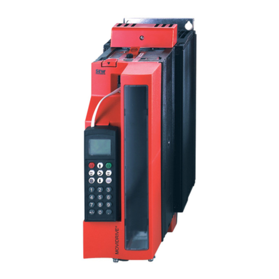
Technical Data and Dimension Sheets DBG60B keypad option 2.10 DBG60B keypad option ® Description The basic version of MOVIDRIVE does not have a DBG60B keypad and can be upgraded to include the keypad as an option. Keypad Language variants Part number DE/EN/FR/IT/ES/PT/NL DBG60B-01 (German / English / French / Italian / Spanish / Portuguese /... - Page 68 Technical Data and Dimension Sheets DBG60B keypad option NOTE The DBG60B keypad option and the interface adapter are plugged into the same inverter slot (XT) and therefore cannot be used at the same time. Dimension draw- Dimensions in mm (in) ing for DBG60B 45 (1.8) 18 (0.71)
- Page 69 Technical Data and Dimension Sheets DBG60B keypad option Dimension The DBM60B option can be used to mount the keypad close to the inverter (e.g. in the drawing for control cabinet door). The DBM60B option consists of housing in enclosure IP65 and a DBG60B housing 5 m DKG60B extension cable.
-
Page 70: Dmp11B Mounting Panel Option
Technical Data and Dimension Sheets DMP11B mounting panel option 2.11 DMP11B mounting panel option Part number 818 398 8 Description DMP11B 54588AXX ® ® If a MOVIDRIVE MD_60A size 2 unit is to be replaced by MOVIDRIVE MDX61B size 2S, the MDX61B size 2S can be fitted on the existing mounting plate with the DMP11B mounting panel. -
Page 71: Dlb11B Touch Guard Option
Technical Data and Dimension Sheets DLB11B touch guard option 2.12 DLB11B touch guard option Part number 823 111 7 (12 pieces included in the scope of delivery) Description 63233AXX ® Degree of protection IP20 can be achieved with touch guard DLB11B for MOVIDRIVE MDX61B sizes 4 and 5 (AC 500 V units: MDX61B0370/0450/0550/0750;... -
Page 72: Hiperface® Encoder Card Option Type Deh11B
Technical Data and Dimension Sheets HIPERFACE® encoder card option type DEH11B ® 2.13 HIPERFACE encoder card option type DEH11B Part number 824 310 7 ® Description The option capable MOVIDRIVE MDX61B units can be equipped with the ® HIPERFACE encoder card type DEH11B. The encoder card offers one input for the motor encoder and one input for an external encoder, also referred to as synchronous encoder. -
Page 73: Absolute Encoder Card Option Type Deh21B/Dip11B
Technical Data and Dimension Sheets Absolute encoder card option type DEH21B/DIP11B 2.14 Absolute encoder card option type DEH21B/DIP11B Part numbers • DEH21B: 1820 818 5 • DIP11B: 824 969 5 ® Description The DEH21B and DIP11B options extend the MOVIDRIVE B system to include an SSI interface for absolute encoders. - Page 74 Technical Data and Dimension Sheets Absolute encoder card option type DEH21B/DIP11B Electronics data for DIP11B DIP11B option Connection binary inputs X60:1 ... 8 DI10 ... DI17 isolated via optocoupler, PLC compatible (EN 61131), scanning time 1 ms ≈ 3 kΩ , I ≈...
-
Page 75: Resolver Card Option Type Der11B
Technical Data and Dimension Sheets Resolver card option type DER11B 2.15 Resolver card option type DER11B Part number 824 307 7 ® Description Option-capable MOVIDRIVE MDX61B units can be equipped with resolver card type DER11B. The resolver card offers one input for the resolver as motor encoder and one input for an external encoder, also referred to as synchronous encoder. -
Page 76: Connector Adapter For Unit Replacement Md_60A - Mdx60B/61B
Technical Data and Dimension Sheets Connector adapter for unit replacement MD_60A - MDX60B/61B 2.16 Connector adapter for unit replacement MD_60A - MDX60B/61B ® The following adapters are available for rapid replacement of a MOVIDRIVE A unit with ® a MOVIDRIVE B unit during system operation. - Page 77 Technical Data and Dimension Sheets Connector adapter for unit replacement MD_60A - MDX60B/61B Terminal of the 15-pin sub D connector Core color in Terminal of 9-pin sub ® (MOVIDRIVE MDX61B, option DEH11B, X15) prefabricated cable D socket (encoder end) Yellow (YE) Red (RD) Pink (PK) Violet (VT)
-
Page 78: Interface Adapter Option Type Dwe11B/12B
Technical Data and Dimension Sheets Interface adapter option type DWE11B/12B 2.17 Interface adapter option type DWE11B/12B Part number and • DWE11B, part number 188 187 6 description The interface adapter DWE11B (HTL→TTL) in the form of an adapter cable is used to connect single-ended HTL encoders to the DEH11B/DEH21B option. - Page 79 Technical Data and Dimension Sheets Interface adapter option type DWE11B/12B • DWE12B, part number 188 180 9 The interface adapter DWE12B (HTL→TTL) in the form of an adapter cable is used to connect single-ended HTL encoders to the DEH11B/DEH21B option. In addition to the A, B and C track, you will also have to connect the negated tracks (A, B, C).
-
Page 80: Interface Adapter Option Type Uws11A
Technical Data and Dimension Sheets Interface adapter option type UWS11A 2.18 Interface adapter option type UWS11A Part number 822 689 X Description The UWS11A option converts RS232 signals, for example from the PC, into RS485 signals. These RS485 signals can then be routed to the RS485 interface of the ®... -
Page 81: Interface Adapter Option Type Uws21B
Technical Data and Dimension Sheets Interface adapter option type UWS21B 2.19 Interface adapter option type UWS21B Part number 1820 456 2 Description The UWS21B option converts RS232 signals, for example from the PC, into RS485 ® signals. These RS485 signals can then be routed to the XT slot of MOVIDRIVE RS232 interface The connection of UWS21B with PC is made using a standard serial interface cable (shielded). -
Page 82: Interface Adapter Option Type Usb11A
Technical Data and Dimension Sheets Interface adapter option type USB11A 2.20 Interface adapter option type USB11A Part number 824 831 1 Description Option USB11A enables a PC or laptop with a USB interface to be connected to the XT ® slot of MOVIDRIVE B. -
Page 83: Dc 5 V Encoder Power Supply Option Type Dwi11A
Technical Data and Dimension Sheets DC 5 V encoder power supply option type DWI11A 2.21 DC 5 V encoder power supply option type DWI11A Part number 822 759 4 Description If you are using an incremental encoder with a DC 5 V encoder power supply, install the DC 5 V encoder power supply option type DWI11A between the inverter and the incremental encoder. -
Page 84: Input/Output Card Type Dio11B Option
Technical Data and Dimension Sheets Input/output card type DIO11B option 2.22 Input/output card type DIO11B option Part number 824 308 5 ® Description The number of inputs/outputs of the basic MOVIDRIVE B unit can be expanded with the DIO11B option. The DIO11B option is plugged into the fieldbus slot. If the fieldbus slot is not available, you can plug the DIO11B option into the expansion slot. -
Page 85: Profibus Fieldbus Interface Option Type Dfp21B
Technical Data and Dimension Sheets PROFIBUS fieldbus interface option type DFP21B 2.23 PROFIBUS fieldbus interface option type DFP21B Part number 824 240 2 ® Description MOVIDRIVE B can be equipped with a 12 Mbaud fieldbus interface for the PROFIBUS- ® DP serial bus system. -
Page 86: Interbus Fieldbus Interface Option Type Dfi11B
Technical Data and Dimension Sheets INTERBUS fieldbus interface option type DFI11B 2.24 INTERBUS fieldbus interface option type DFI11B Part number 824 309 3 ® Description MOVIDRIVE B can be equipped with a fieldbus interface for the non-proprietary and standardized INTERBUS sensor/actuator bus system. INTERBUS is defined in EN 50254 / DIN 19258 and, as far as its function is concerned, it consists of a process data channel and a parameter data channel. -
Page 87: Interbus-Lwl Fieldbus Interface Option Type Dfi21B (Fo)
Technical Data and Dimension Sheets INTERBUS-LWL fieldbus interface option type DFI21B (FO) 2.25 INTERBUS-LWL fieldbus interface option type DFI21B (FO) Part number 824 311 5 ® Description MOVIDRIVE B can be equipped with a fieldbus interface for the non-proprietary and standardized INTERBUS sensor/actuator bus system INTERBUS with fiber optic cables (INTERBUS-LWL). -
Page 88: Dfe11B Fieldbus Interface Option Modbus/Tcp
Technical Data and Dimension Sheets DFE11B fieldbus interface option Modbus/TCP 2.26 DFE11B fieldbus interface option Modbus/TCP Part number 1820 036 2 ® Description The MOVIDRIVE MDX61B inverter enables you to use the DFE11B option to connect to higher-level automation, project planning and visualization systems via Ethernet (MODUBUS/TCP protocol) thanks to its powerful, universal fieldbus interface. -
Page 89: Profinet Io Rt Type Dfe12B Fieldbus Interface Option
Technical Data and Dimension Sheets PROFINET IO RT type DFE12B fieldbus interface option 2.27 PROFINET IO RT type DFE12B fieldbus interface option Part number 1820 563 1 ® Description The MOVIDRIVE MDX61B inverter enables you to use the DFE12B option to connect to higher-level automation, project planning and visualization systems via Ethernet (PROFINET/IO protocol) thanks to its powerful, universal fieldbus interface. -
Page 90: Profinet Io Rt Type Dfe32B Fieldbus Interface Option
Technical Data and Dimension Sheets PROFINET IO RT type DFE32B fieldbus interface option 2.28 PROFINET IO RT type DFE32B fieldbus interface option Part number 1821 345 6 ® Description The MOVIDRIVE MDX61B inverter enables you to use the DFE32B option to connect to higher-level automation, project planning and visualization systems via Ethernet (PROFINET/IO protocol) thanks to its powerful, universal fieldbus interface. -
Page 91: Dfe13B Ethernet/Ip Fieldbus Interface Option
Technical Data and Dimension Sheets DFE13B EtherNet/IP fieldbus interface option 2.29 DFE13B EtherNet/IP fieldbus interface option Part number 1820 565 8 ® Description The MOVIDRIVE MDX61B inverter enables you to use the DFE13B option to connect to higher-level automation, project planning and visualization systems via Ethernet (EtherNet/IP protocol) thanks to its powerful, universal fieldbus interface. -
Page 92: Dfe33B Ethernet/Ip Fieldbus Interface Option
Technical Data and Dimension Sheets DFE33B EtherNet/IP fieldbus interface option 2.30 DFE33B EtherNet/IP fieldbus interface option Part number 1821 346 4 ® Description The MOVIDRIVE MDX61B inverter enables you to use the DFE33B option to connect to higher-level automation, project planning and visualization systems via Ethernet (EtherNet/IP protocol) thanks to its powerful, universal fieldbus interface. -
Page 93: Ethercat Fieldbus Interface Option Type Dfe24B
Technical Data and Dimension Sheets EtherCAT fieldbus interface option type DFE24B 2.31 EtherCAT fieldbus interface option type DFE24B Part number 1821 126 7 ® Description The MOVIDRIVE MDX61B inverter enables you to use the DFE24B option to connect to higher-level automation, project planning and visualization systems via EtherCAT thanks to its powerful, universal fieldbus interface. -
Page 94: Devicenet Fieldbus Interface Option Type Dfd11B
Technical Data and Dimension Sheets DeviceNet fieldbus interface option type DFD11B 2.32 DeviceNet fieldbus interface option type DFD11B Part number 824 972 5 ® Description The MOVIDRIVE MDX61B inverter in conjunction with the DFD11B option allows connection to higher-level automation, project planning and visualization systems via the open and standardized DeviceNet fieldbus system thanks to the option’s high- performance universal fieldbus interface. -
Page 95: Canopen Fieldbus Interface Option Type Dfc11B
Technical Data and Dimension Sheets CANopen fieldbus interface option type DFC11B 2.33 CANopen fieldbus interface option type DFC11B Part number 824 317 4 ® Description The MOVIDRIVE MDX61B inverter in conjunction with the DFC11B option allows connection to higher-level automation, project planning and visualization systems via the open and standardized CANopen fieldbus system thanks to the option’s high- performance universal fieldbus interface. -
Page 96: Synchronous Operation Board Option Type Drs11B
Technical Data and Dimension Sheets Synchronous operation board option type DRS11B 2.34 Synchronous operation board option type DRS11B Part number 824 672 6 Description The DRS11B option enables a group of motors to run in angular synchronous operation or in an adjustable proportional relationship. For detailed information, refer to the "Syn- chronous Operation Board Type DRS11B"... -
Page 97: Profibus Dp-V1 With Profisafe Fieldbus Interface Option Type Dfs11B
Technical Data and Dimension Sheets PROFIBUS DP-V1 with PROFIsafe fieldbus interface option type DFS11B 2.35 PROFIBUS DP-V1 with PROFIsafe fieldbus interface option type DFS11B Part number 1820 962 9 ® Description MOVIDRIVE B can be equipped with a 12 Mbaud fieldbus interface DFS11B for the PROFIBUS-DP-V1 serial bus system with PROFIsafe. - Page 98 Technical Data and Dimension Sheets PROFIBUS DP-V1 with PROFIsafe fieldbus interface option type DFS11B Safety part Safety characteristics Highest possible safety category • SIL 3 according to EN 61508 • Category 4 according to EN 954-1 • Performance level e according to EN ISO 13849-1 System structure 2 channels with diagnostics (1002D) Type of operating mode...
-
Page 99: Profibus Dp-V1 With Profisafe Fieldbus Interface Option Type Dfs12B
Technical Data and Dimension Sheets PROFIBUS DP-V1 with PROFIsafe fieldbus interface option type DFS12B 2.36 PROFIBUS DP-V1 with PROFIsafe fieldbus interface option type DFS12B Part number 1820 963 7 (in preparation) ® Description MOVIDRIVE B can be equipped with a 12 Mbaud fieldbus interface DFS12B for the PROFIBUS-DP-V1 serial bus system with PROFIsafe. -
Page 100: Profinet Io With Profisafe Fieldbus Interface Option, Type Dfs21B
Technical Data and Dimension Sheets PROFINET IO with PROFIsafe fieldbus interface option, type DFS21B 2.37 PROFINET IO with PROFIsafe fieldbus interface option, type DFS21B Part number 1821 183 6 ® Description The MOVIDRIVE MDX61B inverter enables you to use the DFS21B option to connect to higher-level automation, project planning and visualization systems via Ethernet (PROFINET/IO RT protocol) thanks to its powerful, universal fieldbus interface. - Page 101 Technical Data and Dimension Sheets PROFINET IO with PROFIsafe fieldbus interface option, type DFS21B Safety part Safety characteristics Highest possible safety category • SIL 3 according to EN 61508 • Category 4 according to EN 954-1 • Performance level e according to EN ISO 13849-1 System structure 2 channels with diagnostics (1oo2D) Type of operating mode...
-
Page 102: Profinet Io With Profisafe Fieldbus Interface Option, Type Dfs22B
Technical Data and Dimension Sheets PROFINET IO with PROFIsafe fieldbus interface option, type DFS22B 2.38 PROFINET IO with PROFIsafe fieldbus interface option, type DFS22B Part number 1821 184 4 ® Description The MOVIDRIVE MDX61B inverter enables you to use the DFS22B option to connect to higher-level automation, project planning and visualization systems via Ethernet (PROFINET/IO RT protocol) thanks to its powerful, universal fieldbus interface. -
Page 103: Movisafe® Dcs21B/31B Safety Module Option
Technical Data and Dimension Sheets MOVISAFE® DCS21B/31B safety module option ® 2.39 MOVISAFE DCS21B/31B safety module option Part numbers • DCS21B complete with prefabricated cable DAE34B (CAN bus connection between DCS21B X86 and DFS21B X31): 1821 895 4 • DCS21B without prefabricated cable: 1820 392 2 •... - Page 104 Technical Data and Dimension Sheets MOVISAFE® DCS21B/31B safety module option Electronics data DCS21B/31B option LED alarm/error LED watchdog LED system B LED system A X80: Power supply connection X81: Connection binary inputs X82: Connection of binary outputs DO0, DO1 X83: Connection of binary output DO2 X84: Connection of incremental, sin/cos or absolute encoder (encoder 1) X85: Connection of incremental, sin/cos or absolute encoder (encoder 2) X86: CAN bus connection (only for DCS21B)
-
Page 105: Movi-Plc® Basic Dhp11B.. Controller Option
Technical Data and Dimension Sheets MOVI-PLC® basic DHP11B.. controller option ® 2.40 MOVI-PLC basic DHP11B.. controller option ® Part numbers The MOVI-PLC basic controller DHP11B.. is available in 3 versions, which differ in the modules available from a range of libraries. ®... -
Page 106: Ost11B Option
Technical Data and Dimension Sheets OST11B option 2.41 OST11B option Part number 1820 544 5 ® Description Option OST11B provides an additional RS485 interface (COM2) for MOVI-PLC basic DHP11B.. in terminal design or as an engineering interface. Only use option OST11B in ®... -
Page 107: Movi-Plc® Advanced Controller Option Dh.41B
Technical Data and Dimension Sheets MOVI-PLC® advanced controller option DH.41B ® 2.42 MOVI-PLC advanced controller option DH.41B ® Part numbers The MOVI-PLC advanced DH.41B is available in 2 variants, which differ in the integrated fieldbus interfaces: ® Part number Unit design of MOVI-PLC Fieldbus interfaces advanced DH.41B 1821 160 7... - Page 108 Technical Data and Dimension Sheets MOVI-PLC® advanced controller option DH.41B Electronics data for DHE41B ® MOVI-PLC advanced DHE41B option Electrical supply The following applies for all units (MDX, MX, compact controller): • You will have to supply the binary inputs and outputs with DC 24 V (X31:1/2) separately. ®...
- Page 109 Technical Data and Dimension Sheets MOVI-PLC® advanced controller option DH.41B ® MOVI-PLC advanced DHE41B option System bus CAN 2 • System bus CAN 1 and CAN 2 to CAN specification 2.0, parts A and B, transmission X32:1 ... X32:3 technology to ISO 11898, max. 64 stations, •...
- Page 110 Technical Data and Dimension Sheets MOVI-PLC® advanced controller option DH.41B Electronics data for DHF41B NOTE For connections identical with DHE41B, refer to the "Electronics data for DHE41B" section. ® MOVI-PLC advanced DHF41B option ® Potential levels The MOVI-PLC advanced DHF41B controller has the following potential levels: •...
-
Page 111: Braking Resistor Type Bw
Technical Data and Dimension Sheets Braking resistor type BW... option / BW...-T / BW...-P 2.43 Braking resistor type BW... option / BW...-T / BW...-P General • Braking resistors BW... / BW...-T and BW...-P match the technical features of the ® information MOVIDRIVE inverters. - Page 112 Technical Data and Dimension Sheets Braking resistor type BW... option / BW...-T / BW...-P Parallel Two braking resistors with the same value must be connected in parallel for some connection inverter/resistor combinations. In this case, the trip current must be set on the bimetallic relay to twice the value of I entered in the table.
- Page 113 Technical Data and Dimension Sheets Braking resistor type BW... option / BW...-T / BW...-P Braking resistor type BW... BW147 BW247 BW347 BW039-012 Part number 820 713 5 820 714 3 820 798 4 821 689 4 Braking resistor type BW...-T BW147-T BW247-T BW347-T...
- Page 114 Technical Data and Dimension Sheets Braking resistor type BW... option / BW...-T / BW...-P Braking resistor type BW...- BW012-025 Part number 821 680 0 Braking resistor type BW...-T/-P BW012-025-P BW012-050T BW012-100-T BW106-T BW206-T Part number 1820 414 7 1820 140 7 1820 141 5 1820 083 4 1820 412 0...
- Page 115 Technical Data and Dimension Sheets Braking resistor type BW... option / BW...-T / BW...-P Assignment to AC 230 V units (...-2_3) Braking resistor type BW... BW039- BW039- BW039- BW027- BW027- Part number 821 687 8 821 688 6 821 689 4 822 422 6 822 423 4 Braking resistor type BW...-T BW039-...
- Page 116 Technical Data and Dimension Sheets Braking resistor type BW... option / BW...-T / BW...-P MDimension drawing braking resistors BW... / BW...-T / BW...-P BW... : • 1 = Flat design The connecting lead is 500 mm (19.7 in) long. The scope of delivery includes four M4 stud bolts each of type 1 and •...
- Page 117 Technical Data and Dimension Sheets Braking resistor type BW... option / BW...-T / BW...-P Touch guard BS... A BS.. touch guard is available for braking resistors in flat design. Touch guard BS003 BS005 Part number 813 151 1 813 152 X for braking resistor BW027-003 BW027-005...
- Page 118 Technical Data and Dimension Sheets Braking resistor type BW... option / BW...-T / BW...-P DKB11A heat sink for braking resistors in flat design Part number 814 345 5 Description The DKB11A heat sink for braking resistors in flat design provides a space-saving means for mounting the braking resistors (BW072-005, BW100-005) beneath ®...
-
Page 119: Line Choke Option Type Nd
Technical Data and Dimension Sheets Line choke option type ND.. 2.44 Line choke option type ND.. • To increase overvoltage protection. • To limit the charging current when several inverters are connected together in parallel on the input end with shared mains contactors (rated current of line choke = total of inverter currents). - Page 120 Technical Data and Dimension Sheets Line choke option type ND.. 58315AXX Figure 29: Dimension drawing for line chokes ND150.. / ND200.. / ND300.. Hole dimension Main dimensions mm (in) Mounting dimensions mm (in) Weight Line choke mm (in) type kg (lb) ND020-013 85 (3.3) 60 (2.4)
-
Page 121: Line Filter Type Nf
Technical Data and Dimension Sheets Line filter type NF...-... option 2.45 Line filter type NF...-... option • To suppress interference emission on the line side of inverters. ® • Do not switch between the NF... line filter and MOVIDRIVE ® •... - Page 122 Technical Data and Dimension Sheets Line filter type NF...-... option Dimension draw- ing for NF... Eingang Ausgang 55862ADE Figure 30: Dimension drawing for NF line filter Any mounting position Mounting dimensions mm Hole dimension Main dimensions mm (in) Weight Line filter (in) mm (in) type...
-
Page 123: Hd... Output Choke Option
Technical Data and Dimension Sheets HD... output choke option 2.46 HD... output choke option • For suppression of interference from the unshielded motor cable. For HD001 to HD003 we recommend routing the motor cable through the output choke with 5 loops. - Page 124 Technical Data and Dimension Sheets HD... output choke option ® MOVIDRIVE HD004 58424AXX Mounting dimensions mm Hole dimen- Inside ∅ mm (in) Main dimensions mm (in) Weight Output (in) sion mm (in) choke type kg (lb) HD001 121 (4.76) 64 (2.5) 131 (5.16) 80 (3.1) 50 (2.0)
-
Page 125: Output Filter Option Type Hf
Technical Data and Dimension Sheets Output filter option type HF... 2.47 Output filter option type HF... HF... output filters are sine filters used to smooth output voltage from inverters. HF... output filters (with the exception of HF450-503) are approved to UL/cUL in combination ®... - Page 126 Technical Data and Dimension Sheets Output filter option type HF... Output filter type HF075-503 HF023-403 HF033-403 HF047-403 HF450-503 Part number 826 313 2 825 784 1 825 785 X 825 786 8 826 948 3 3 × AC 230 V - 500 V, 50/60 Hz Rated voltage ΔI Earth-leakage current at U...
- Page 127 Technical Data and Dimension Sheets Output filter option type HF... Dimension drawings for HF...-503 output filters HF008 / 015 / 022 / 030-503 HF040/055/075-503 MOVIDRIVE ® MOVIDRIVE ® MOVIDRIVE ® 58418AXX Figure 31: Dimension drawings for output filters HF008...075-503 Only the mounting position shown in the dimension drawing is permitted. Mounting dimensions Hole dimen- Ventilation clearances...
- Page 128 Technical Data and Dimension Sheets Output filter option type HF... Dimension drawing for HF...-403 output filter 58996AXX Figure 33: Dimension drawing for HF...-403 output filter Mounting dimensions mm (in) Hole dimen- Ventilation clearances Horizontal Main dimensions mm (in) Standard mounting sion mm mm (in) mounting...
-
Page 129: Prefabricated Cables
Technical Data and Dimension Sheets Prefabricated cables 2.48 Prefabricated cables Overview SEW offers cable sets and prefabricated cables for straightforward and error-free ® connection of various system components to MOVIDRIVE . The cables are pre- fabricated in 1 m steps to the required length. It is necessary to differentiate between whether the cables are intended for fixed routing or for cable carrier applications. - Page 130 Technical Data and Dimension Sheets Prefabricated cables 2. Prefabricated cables and extension cables for connecting CM motors to MDX Motor cables The cables are equipped with a connector for motor connection and conductor end sleeves for inverter connection. Number of cores and line cross section Part number Installation type for motor...
- Page 131 Technical Data and Dimension Sheets Prefabricated cables Number of cores and line cross section Part number Installation type for motor 4×1.5 mm 1 333 118 3 CM..SM51 4×1.5 mm + 3×1.0 mm 1 333 120 5 CM..BR SB51 4×2.5 mm 1 333 119 1 CM..SM52 4×2.5 mm...
- Page 132 Technical Data and Dimension Sheets Prefabricated cables 4. Prefabricated cables and extension cables for connecting VR forced cooling fans VR forced cooling fan cable: Number of cores and line cross section Part number Installation type 3×1 mm 198 634 1 Fixed installation 3×1 mm 199 560 X...
- Page 133 Technical Data and Dimension Sheets Prefabricated cables 5. Prefabricated cables for connecting options DEH11B / DEH21B / DER11B The following overviews show the possible connections for the DEH11B/DEH21B and DER11B options. Meaning of the The connection cables are assigned a part number and a symbol. The symbols have the symbols following meaning: Symbol...
- Page 134 Technical Data and Dimension Sheets Prefabricated cables Connection options at X15 X15 DEH11B/DEH21B DS, CM, CMD, CMP DT(E)/DV(E), CT/CV, DZ/DX AF1H, AK0H, AS1H, AS3H, AS4H EF1H, EK0H, ES1H, ES3H, ES4H EV1H, AV1H AS1H, ES1H AS1H, ES1H ® Hiperface 199 539 1 199 540 5 X15 DEH.1B ®...
- Page 135 Technical Data and Dimension Sheets Prefabricated cables ® • Cable to connect HIPERFACE encoders AF1H, AK0H, AS1H, AS3H, AS4H, EF1H, EK0H, ES1H, ES3H, ES4H, EV1H, AV1H with plug connector connection on the motor side to DS, CM, CMD, CMP, DT, DV, DT(E), DV(E), CT, CV, DZ or DX motors. 56135AXX Type Installation...
- Page 136 Technical Data and Dimension Sheets Prefabricated cables ® • Cable to connect HIPERFACE encoders AS1H, ES1H, AF1H, EF1H with terminal box connection on the motor side to DS motors. 56132AXX Type Installation Part number 1332 765 8 56049AXX DEH11B/21B X15 → DS motors with AS1H, ES1H, AF1H, EF1H 1332 766 6 56050AXX...
- Page 137 Technical Data and Dimension Sheets Prefabricated cables Cable (option DWE12B, interface adapter HTL → TTL) to connect push-pull HTL • encoders at X15 of option (→ chapter "Interface adapter DWE11B/12B"). 59109AXX Type Installation Part number DEH11B/21B X15 → Option DWE12B (connection 188 180 9 for push-pull HTL encoders) 56047AXX...
- Page 138 Technical Data and Dimension Sheets Prefabricated cables • Cable to connect DC 5 V TTL sensors ES1T, ES2T, EV1T, EV2T, EH1T with terminal box connection on the motor side (DT(E), DV(E), eDT, eDV, DR, DZ or DX motors) to DC 5 V encoder power supply type DWI11A. 56132AXX Type Installation...
- Page 139 Technical Data and Dimension Sheets Prefabricated cables • Y cable to connect the AV1Y absolute encoder with plug connector on the motor side to DT(E), DV(E), CT, CV, DR, DZ and DX motors. The following encoder tracks are evaluated with the Y cable: –...
- Page 140 Technical Data and Dimension Sheets Prefabricated cables Connection options at X14, DEH11B / DER11B AV1H EV1S, EV1R EV1T ® Hiperface DWI11A 199 539 1 X2 DWI11A X14 DER11B/DEH11B → TTL/5V → TTL, Sin/Cos 199 540 5 198 829 8 817 960 3 X14 DER11B/ DEH11B 198 828 X...
- Page 141 Technical Data and Dimension Sheets Prefabricated cables ® • Cable to connect external HIPERFACE encoders AV1H, AS1H, ES1H, AF1H, EF1H via plug connector. 56131AXX Type Installation Part number 199 539 1 56051AXX DEH11B / DER11B X14 → AV1H, AS1H, ES1H, AF1H, EF1H 199 540 5 56052AXX...
- Page 142 Technical Data and Dimension Sheets Prefabricated cables • Cable to connect the DC 5 V encoder power supply type DWI11A via plug connector. 56109AXX Type Installation Part number DEH11B / DER11B X14 → DWI11A X1 818 164 0 56047AXX • Cable to connect an external DC 5 V TTL sensor to the DC 5 V encoder power supply type DWI11A via encoder terminal strip.
- Page 143 Technical Data and Dimension Sheets Prefabricated cables • Cable to connect the encoder simulation (DEH11B/DER11B:X14) of the master to terminal X42 of option DRS11B. 56109AXX Type Installation Part number DEH11B/DER11B X14 → DRS11B X42 0818 166 7 (master and slave turn in the same direction) 56047AXX DEH11B/DER11B X14 →...
- Page 144 Technical Data and Dimension Sheets Prefabricated cables Connection options at X15 DER11B X15 DER11B → RH1M/L X15 DER11B → RH1M/L X15 DER11B 1332 817 4 → RH1M/L 199 589 8 X62 DIP11B → SSI DER11B 199 487 5 1332 844 1 199 590 1 198 929 4 DIP11B...
- Page 145 Technical Data and Dimension Sheets Prefabricated cables • Cable to connect resolvers RH1M / RH1L with plug connector connection on the motor side to DS, CM, CMD or CMP motors. 56138AXX Type Installation Part number 199 487 5 56047AXX DER11B X15 → DS/CM/CMD/CMP motors with RH1M/RH1L 199 319 4 56048AXX...
- Page 146 Technical Data and Dimension Sheets Prefabricated cables • Cable to connect resolvers RH1M / RH1L with terminal box connection on the motor side to CM and DS motors. 56142AXX Type Installation Part number 199 589 8 56049AXX DER11B X15 → CM motors with RH1M/RH1L 199 590 1 56050AXX 1332 817 4...
-
Page 147: Parameters
P6.. Parameters Menu structure DBG60B P60. P600 Parameters Generally speaking, the parameter menu is only required for startup and in case of ® service. That is the reason why MOVIDRIVE is designed as a basic unit without key- ® pad. You can equip the MOVIDRIVE with a PC connection or a keypad. -
Page 148: Overview Of Parameters
P6.. Parameters Overview of parameters P60. P600 Overview of parameters The following table lists all parameters together with their factory settings (underlined): Numerical values are displayed with the complete setting range. Display values Process values Speed User display Frequency Actual position Output current Active current 006 / 007... - Page 149 P6.. Parameters Overview of parameters P60. P600 Option / firmware expansion slot Firmware basic unit Technology function Unit type Error memory 080 ... Error t-0 ... t-4 Bus diagnostics PD configuration Fieldbus type Fieldbus baud rate Fieldbus address 094 ... PO1 ...
- Page 150 P6.. Parameters Overview of parameters P60. P600 16x / 17x Fixed setpoints 1 / 2 160 / 170 Internal setpoint n11 / n21 –6000 ... 150 ... 6000 rpm (% I 161 / 171 Internal setpoint n12 / n22 –6000 ... 750 ... 6000 rpm (% I 162 / 172 Internal setpoint n13 / n23 –6000 ...
- Page 151 P6.. Parameters Overview of parameters P60. P600 Scaling setpoint –32.767 ... 1 ... 32.767 Actual value source Analog 1 IPOS actual value address 0 ... 1023 Actual scaling factor –32.767 ... 1 ... 32.767 Actual offset value –32767 ... 0 ... 32767 Actual time constant 0 ...
- Page 152 P6.. Parameters Overview of parameters P60. P600 Speed setpoint/actual value comparison Hysteresis 0 ... 100 ... 300 rpm Delay time 0 ... 1 ... 9 s n ≠ n Signal = "1" if: / n = n setpt setpt Current reference signal Current reference value 0 ...
- Page 153 P6.. Parameters Overview of parameters P60. P600 Binary inputs DCS 1 ... 8 Display value Binary outputs DCS DO0_P ... Display value DO2_M Serial number DCS Display value CRC DCS Display value DCS error response Immediate stop/fault DCS alarm response Rapid stop / warning DCS source actual position Motor encoder (X15)
- Page 154 P6.. Parameters Overview of parameters P60. P600 720 / 723 Setpoint stop function 1 / 2 721 / 724 Stop setpoint 1 / 2 0 ... 30 ... 500 rpm 722 / 725 Start offset 1 / 2 0 ... 30 ... 500 rpm Brake function 730 / 733 Brake function 1 / 2...
- Page 155 P6.. Parameters Overview of parameters P60. P600 Response SW LIMIT SWITCH EMERG. ST/FAULT Reset behavior Manual reset Auto reset Restart time 1 ... 3 ... 30 s Scaling actual speed value Scaling factor numerator 1 ... 65 535 Scaling factor denominator 1 ...
- Page 156 P6.. Parameters Overview of parameters P60. P600 Ramp type LINEAR Ramp mode MODE 1 IPOS Monitoring SW limit switch RIGHT –(2 –1) ... 0 ... 2 –1 increments SW limit switch LEFT –(2 –1) ... 0 ... 2 –1 increments Position window 0 ...
-
Page 157: Explanation Of The Parameters
P6.. Parameters Explanation of the parameters P60. P600 Explanation of the parameters The parameters are explained below. The parameters are divided into 10 groups. The ® parameter names correspond to their representation in the SHELL PC program. The factory setting is indicated by underline. Symbols The following symbols explain the parameters: These parameters are switch-selectable and available in parameter sets 1 and 2. - Page 158 P6.. Parameters Explanation of the parameters P60. P600 P0xx display values This parameter group contains the following information: • process values and states of the basic unit • process values and states of the installed options • Error memory • Fieldbus parameters P00x process values P000 Speed...
- Page 159 P6.. Parameters Explanation of the parameters P60. P600 P011 Operating The following operating states are possible (7 segment display): state • 0: 24 V OPERATION (inverter not ready for operation) • 1: CONTROLLER INHIBIT • 2: NO ENABLE • 3: CURRENT AT STANDSTILL •...
- Page 160 P6.. Parameters Explanation of the parameters P60. P600 P03x Binary inputs basic unit P030 ... P037 The display will show the current status of input terminal DI00 ... DI07 and the current binary input DI00 function assignment..DI07 Please note that binary input DI00 is always assigned with controller inhibit. Menu selection see P60x binary inputs basic unit.
- Page 161 P6.. Parameters Explanation of the parameters P60. P600 • ELECTRONIC CAM: Setting for technology function "Electronic cam" to coordinate the operation of several drives. Prerequisites are: – Motor with encoder feedback – Inverter in unit design "Application version" • ISYNCH: Setting for technology function "Electronic synchronous operation" to synchronize the operation of several drives with accurate positioning.
- Page 162 P6.. Parameters Explanation of the parameters P60. P600 P08x Error memory P080 ... P084 Error There are 5 error memories (t-0 ... t-4). The errors are stored in a chronological t-0 ... t4 sequence with the most recent error event being held in error memory t-0. If there are more than 5 errors, the error event of longest standing, stored in t-4, is deleted.
- Page 163 P6.. Parameters Explanation of the parameters P60. P600 P094 ... P096 PO1 Displays the value currently transferred on the process data word in hexadecimal form..PO3 setpoint PO setpoint Description P094 PO1 setpoint P870 Setpoint description PO1 P095 PO2 setpoint P871 Setpoint description PO2 P096 PO3 setpoint P872 Setpoint description PO3...
- Page 164 P6.. Parameters Explanation of the parameters P60. P600 • FIX SETP+ANALOG1: The setpoint is defined by the total of the selected fixed setpoint and the setpoint selection at analog input AI1. The fixed setpoint is processed without sign (= according to its value) and the analog setpoint is processed as a signed setpoint.
- Page 165 P6.. Parameters Explanation of the parameters P60. P600 plus® • SBus 2: The setpoint is specified using system bus 2. (See IPOS manual.) • IPOS setpoint: The value of the IPOS variable H524 (IPOS system setpoint) is used as the setpoint. The setpoint is interpreted depending on P700 Operation mode 1. –...
- Page 166 P6.. Parameters Explanation of the parameters P60. P600 P11x Analog input AI1 P110 AI1 Scaling Setting range: –10 ... 0 ... 1 ... 10 The slope of the setpoint characteristic is defined. Depending on P112 AI1 operation mode with AI1 scaling = 1 and an input voltage V of +/–10 V, the setpoint +/–3000 rpm or +/–n is set.
- Page 167 P6.. Parameters Explanation of the parameters P60. P600 P111 AI1 Offset Setting range: –500 ... 0 ... 500 mV When the setpoint is selected by an external controller, it is possible to compensate for a voltage offset present at analog input AI1 when the setpoint selection is zero. The setting of this parameter causes calibration of the coordinate basic origin of Figure 35.
- Page 168 P6.. Parameters Explanation of the parameters P60. P600 • Expert characteristic: Free choice of reference between setpoint voltage and speed. The characteristic can be adapted with P110 AI1 scaling (reference 3000 rpm), P113 AI1 voltage offset and P114 AI1 speed offset (-> Figure 41). The following structural diagram shows how a speed setpoint is created from an expert characteristics.
- Page 169 P6.. Parameters Explanation of the parameters P60. P600 P114 AI1 speed Setting range: –6000 ... 0 ... 6000 rpm offset The zero passage of the setpoint characteristic can be moved along the n-axis. Reference point with positive offset Reference point with negative offset -10 V -8 V...
- Page 170 P6.. Parameters Explanation of the parameters P60. P600 Sample expert characteristics (P112 AI1 operating mode = Expert charactristic curve): Free choice of reference between setpoint voltage and speed for the expert character- istics. Set parameter P100 Setpoint source = BIPOL./FIX.SETPT to make full use of the possibilities of the expert characteristic.
- Page 171 P6.. Parameters Explanation of the parameters P60. P600 The expert characteristics displayed in Figure 41 are created as follows: Char- P113 P114 P110 acter- AI1 Voltage offset V AI1 Speed offset rpm AI1 scaling (slope) istics curve 1.39 1500 3000 –1.25 The expert characteristic can also be used with P100 Setpoint source = UNIPOL/FIX.SETPT.
- Page 172 P6.. Parameters Explanation of the parameters P60. P600 Expert characteristics with current setpoints: Voltage signals are required at the AI11/AI12 analog input for the expert characteristic function. If a load-independent current 0 (4) ... 20 mA is available as setpoint, switch S11 (changeover I-signal/U-signal) must be set to ON and the current signal routed to X11:2 AI11.
- Page 173 P6.. Parameters Explanation of the parameters P60. P600 P12x Analog inputs option P120 AI2 operating Analog input AI2 is only available with the optional input/output card (DIO11B). mode (optional) • NO FUNCTION: The setpoint at AI2 is not used; the external current limitation is set to 100 %.
- Page 174 P6.. Parameters Explanation of the parameters P60. P600 P135 / P145 S Setting range: 0 / 1 / 2 / 3 (0 = off, 1 = weak, 2 = medium, 3 = strong) pattern t12 / t22 The 2nd ramp (t12/ t22) of parameter sets 1 and 2 can be rounded with 3 pattern grades to achieve a smoother acceleration of the drive.
- Page 175 P6.. Parameters Explanation of the parameters P60. P600 This step also entails an increased setting of the respective ramp, if the ramp timeout definitely appears in form of a preset ramp that cannot be traveled. This parameter is an additional monitoring function for speed monitoring. This parameter only applies to the downwards ramp.
- Page 176 P6.. Parameters Explanation of the parameters P60. P600 P16x / P17x Fixed Setting range: –6000 ..+6000 rpm setpoints 1 / 2 3 internal setpoints (= fixed setpoints) can be set separately for parameter sets 1 and 2. The internal setpoints are active if P100 Setpoint source is set to one of the following functions and an input terminal programmed to n11/n21 or n12/n22 (P6xx Terminal assignment) has a “1”...
-
Page 177: Filter Speed Actual Value 0
P6.. Parameters Explanation of the parameters P60. P600 P2xx Controller parameters P20x Speed Speed control only parameter set 1. control ® The speed controller of the MOVIDRIVE is a PI-controller and is active when the following operating modes are set: •... -
Page 178: Load Precontrol Cfc
P6.. Parameters Explanation of the parameters P60. P600 P204 Actual speed Setting range: 0 ... 32 ms value filter Filter time constant of the actual speed value filter. AUTO P205 Load Load precontrol CFC (only effective in CFC and SERVO operating modes). precontrol CFC Setting range: –150 ... - Page 179 P6.. Parameters Explanation of the parameters P60. P600 P221 / P222 Setting range: 1 ... 3 999 999 999 Master gear ratio These settings are only required with the slave inverter. These parameters set the factor / Slave gear position measurement ratio between the master and slave drives. The ratio is entered ratio factor as the quotient of master to slave drive to include non-integer ratios.
- Page 180 P6.. Parameters Explanation of the parameters P60. P600 • Mode 6: Temporary angular offset, new reference point – Free-running is active when a "1" signal is set at X40:1. – The input terminals and setpoints of the slave drive are effective in free-running mode.
-
Page 181: Master Encoder Resolution
P6.. Parameters Explanation of the parameters P60. P600 P230 Synchro- Setting range: OFF / EQUAL-RANKING / CHAIN nous encoder • OFF: Synchronous operation control with the signals on X15: "Motor encoder". P231 and P232 have no effect. • EQUAL-RANKING: Forwarding of X42 signals: "Master encoder" at X43: "Incremental encoder output."... -
Page 182: Derivative Time T V
P6.. Parameters Explanation of the parameters P60. P600 P263 Factor K Setting range: 0 ...1 ... 32,767 Proportional factor of the proportional share of the PID controller with 3 decimal places. The proportionality factor takes the sign (+/-) of the parameter "Direction of rotation" into account. - Page 183 P6.. Parameters Explanation of the parameters P60. P600 P278 Offset actual Setting range: –32767 ... 0 ... 32767 value This parameter is used to set an integer, permanent offset of the actual value. P278 and the IPOS variable H552 are identical. P279 Time con- Setting range: 0 ...
- Page 184 P6.. Parameters Explanation of the parameters P60. P600 P3xx Motor parameters This parameter group is used to adjust the inverter to the motor. The parameters can be set separately for parameter set 1 and 2. This means two different motors can be operated alternately on the same inverter without requiring a new setting.
- Page 185 P6.. Parameters Explanation of the parameters P60. P600 P304 Torque limit Setting range: 0 ... 150 % (size 0: 200 %) The parameter limits the maximum torque of the motor. The entry acts on the setpoint × I of the motor torque (k ).
- Page 186 P6.. Parameters Explanation of the parameters P60. P600 P322 / P332 IxR Setting range: 0 ... 100 % compensation 1/2 The I×R value of the matching motor is set as the factory setting. In VFC operating mode, this parameter acts on the parameters of the calculated motor model which establish the torque.
- Page 187 P6.. Parameters Explanation of the parameters P60. P600 The following signal and display functions are available in conjunction with motor protection: Parameters Signal and display function P006 Motor utilization 1 / P007 Display of the motor utilization for parameter set 1 / 2. Motor utilization 2 P832 Response MOTOR Error response of the inverter when reaching P006 Motor utilization 1...
- Page 188 P6.. Parameters Explanation of the parameters P60. P600 • SEW motor with KTY temperature sensor: Motor utilization is calculated using a ® motor model stored in MOVIDRIVE (P006 Motor utilization1, P018 KTY utilization 1). Once the motor dependent switch-off limit is reached, the inverter will be switched off using the response set in P832 Response motor utilization.
- Page 189 P6.. Parameters Explanation of the parameters P60. P600 P36x Startup Startup (only available in the DBG60B keypad). P360 Startup Setting range: YES / NO • YES: Begins the startup function with the DBG60B keypad. NOTE ® With P360, MOVIDRIVE B can only be started up in VFC operating modes. Startup in the CFC and SERVO operating modes must be performed using MOVITOOLS/SHELL.
- Page 190 P6.. Parameters Explanation of the parameters P60. P600 P41x Speed Signals whether the speed is within or outside the set window range. window signal n rpm P411 P410 Window P412 P413: Signal = "1" at n <> n Window P413: Signal = "1" at n = n Window 55733BEN...
- Page 191 P6.. Parameters Explanation of the parameters P60. P600 P43x Current Signal if the output current is greater or less than the reference value. reference signal I [% off I ] P431 P430 P432 P433: Signal = "1" at | I | > I P433: Signal = "1"...
- Page 192 P6.. Parameters Explanation of the parameters P60. P600 Activate the speed monitoring for hoists and set the delay time to a rather small value. Speed monitoring is not that important for safety since an incorrect movement of the hoist does not necessarily mean operation in the current limitation. P501 / P503 Delay Setting range: 0 ...
- Page 193 P6.. Parameters Explanation of the parameters P60. P600 P512 Lag error Setting range: 100 ... 4000 ... 99,999,999 inc limit Fault message F42 'Lag error' is issued if the angular misalignment exceeds the value set here. This is regardless of whether the slave drive is operating in free-running or synchronous operation mode.
- Page 194 P6.. Parameters Explanation of the parameters P60. P600 P521 Power off Setting range: CONTROL.INHIBIT / EMERGENCY STOP response If the binary input is programmed to "Power on", the response set here will be triggered ® when the binary receives a "0" signal. The 7-segment display of MOVIDRIVE indicates "0"...
- Page 195 P6.. Parameters Explanation of the parameters P60. P600 P54x Gear unit / motor monitoring These parameters are used to set the response to be triggered in the event of a motor or gear unit problem. The binary inputs have to be set accordingly for this purpose. The fault responses will also be triggered in the CONTROLLER INHIBIT inverter status.
- Page 196 P6.. Parameters Explanation of the parameters P60. P600 P545 Oil aging / Factory setting: Display error ready signal Once the oil aging sensor signals ready, the inverter will respond with the set response. P549 Response Factory setting: Display error brake wear Once the brake wear sensor signals a fault, the inverter will respond with the set response.
- Page 197 P6.. Parameters Explanation of the parameters P60. P600 P555 Error Setting range P555: No response / Display error / Immediate stop / Fault / Emergency response DCS / stop/Fault / Rapid stop/Fault / Immediate stop/Warning / Emergency stop/Warning / P556 Alarm Rapid stop/Warning response DCS Setting range P556: No response / Display error / Rapid stop / Fault / Emergency...
- Page 198 P6.. Parameters Explanation of the parameters P60. P600 P560 Current limi- Setting range: On / Off tation Ex-e motor ON: Current limitation for Ex-e motors active. On startup, the current limitation for Ex-e motors is automatically activated for motors AUTO selected and approved for the operation in potentially explosive areas.
- Page 199 P6.. Parameters Explanation of the parameters P60. P600 P6xx Terminal assignment P60x Binary inputs Binary input DIØØ with fixed assignment "/CONTROL. INHIBIT." basic unit P600 ... P606 The binary inputs of the basic unit can be set to the same functions as the binary outputs Binary inputs DIØ1 option (P61x).
- Page 200 P6.. Parameters Explanation of the parameters P60. P600 Effect in Effect at Fac- Inverter status Function tory set See also "1" signal Inhib- "0" signal Enabled ited Vibration/fault Vibration sensor reports fault Vibration sensor does not report fault Oil aging/warning Oil aging sensor signals Oil aging sensor does not warning...
- Page 201 P6.. Parameters Explanation of the parameters P60. P600 P63x Binary outputs option P630 ... P637 The following functions can be assigned to the binary outputs: Binary output DO1Ø ... DO17 Binary output has Factory set Function See also "0" signal "1"...
- Page 202 P6.. Parameters Explanation of the parameters P60. P600 NOTE The binary signals are only valid if the inverter has signaled "READY" after switch-on. ® Binary signals have "0" status while MOVIDRIVE is being initialized. Several terminals can be assigned the same function. P64x Analog outputs optional P640 / P643 Depending on P642 Operating mode AO1 / P645 Operating mode AO2 the signal range...
- Page 203 P6.. Parameters Explanation of the parameters P60. P600 P641 / P644 Scal- Setting range: –10 ... 0 ... 1 ... 10 ing AO1 / AO2 The incline of the characteristic for the analog outputs is defined. The value for unit utilization, current and relative torque is 200% for each in BG0.
- Page 204 P6.. Parameters Explanation of the parameters P60. P600 P642 / P645 Here you can set the operating mode of the analog output. The following operating Operating mode modes are available: AO1 / AO2 • OFF: The value zero is always output. •...
- Page 205 P6.. Parameters Explanation of the parameters P60. P600 P7xx Control functions All settings with regard to the fundamental control properties of the inverter are defined within parameter group 7xx. These are all functions which the inverter performs auto- matically upon activation and which influence its behavior in certain operating modes. NOTE ®...
- Page 206 P6.. Parameters Explanation of the parameters P60. P600 P71 x Standstill current P710 / P711 Setting range: 0 ... 50 % I Standstill current 1 The standstill current is used for injecting an adjustable current into the motor when the motor is at a standstill and the brake is applied.
- Page 207 P6.. Parameters Explanation of the parameters P60. P600 P72x Setpoint stop The setpoint stop function makes possible an enable function generated automatically function by the inverter depending on the main setpoint. It results in an enable process with all necessary functions, such as premagnetization, brake control, etc. It always requires an additional enable via terminals.
- Page 208 P6.. Parameters Explanation of the parameters P60. P600 ® P73x Brake MOVIDRIVE B inverters are capable of controlling a brake installed on the motor. The function brake function acts on the binary output DBØØ, which has the fixed assignment of the “/BRAKE”...
- Page 209 P6.. Parameters Explanation of the parameters P60. P600 P74x Speed skip The skip window center and skip width are values and automatically have an effect on positive and negative setpoints when activated. The function is deactivated by setting the skip width to 0. Output speed P741/P743 Ramps...
- Page 210 P6.. Parameters Explanation of the parameters P60. P600 P75x Master-Slave The master-slave function allows for implementing automatical functions such as speed function synchronization, shared load and torque control (slave). The RS485 interface (ST11 ST12) or the system bus interface (SC11 / SC12) can be used as the communication link.
- Page 211 P6.. Parameters Explanation of the parameters P60. P600 Connection check • System bus (SBus): P815 SBus timeout delay is in effect when there is a communi- cation link via the SBus. If P883 SBus timeout delay = 0, there is no monitoring of data transmission via the SBus.
- Page 212 P6.. Parameters Explanation of the parameters P60. P600 Synchronous Speed synchronization (SPEED (RS485) / SPEED (SBus) / SPEED (485+SBus)): speed running The actual speed of the master is transferred to the slave. The speed ratio is set for the slave inverter with P751 Scaling slave setpoint. Leave P324 Slip compensation 1 / P334 Slip compensation 2 of the slave at the value of the startup setting.
- Page 213 P6.. Parameters Explanation of the parameters P60. P600 Example: Parameters Setting on the master Setting on the slave P100 Setpoint source e.g. BIPOL./FIXED SETP MASTER RS485 P101 Control signal source e.g. TERMINALS Not in effect P324 Slip compensation 1 Do not change P700 Operating mode 1 VFC 1 VFC 1...
- Page 214 P6.. Parameters Explanation of the parameters P60. P600 P751 Scaling slave Setting range: –10 ... 1 ... 10 setpoint The setpoint sent from the master is multiplied by this factor which is set in the slave. P76x Manual operation P760 Lockout Setting range: YES / NO run/stop keys NO: Run/stop keys of the DBG60B keypad are active and can be used for starting and...
- Page 215 P6.. Parameters Explanation of the parameters P60. P600 P785 Ethernet / IP Setting range: DHCP / Saved IP parameters Startup Configura- Only available with DFE13B EtherNet/IP option. tion: • DHCP: The DFE13B option is assigned its IP parameters (P780 ... P782) P782) by a DHCP server when the supply voltage is switched on.
- Page 216 P6.. Parameters Explanation of the parameters P60. P600 • P94x IPOS encoder (except for P944) • P95x DIP (except for P955) • Error memory • Statistical data • PROFINET device name The "Delivery state" setting also resets the data listed above. "8"...
- Page 217 P6.. Parameters Explanation of the parameters P60. P600 P806 Copy DBG -> Setting range: YES / NO ® The parameter data in the DBG60B are transferred to MOVIDRIVE P807 Copy MDX - Setting range: YES / NO > DBG ® The parameter data set in MOVIDRIVE are transferred to the DBG60B keypad.
- Page 218 P6.. Parameters Explanation of the parameters P60. P600 P82x Braking operation P820 / P821 Setting range: ON / OFF 4-quadrant This setting is only taken into account in operating modes without encoder feedback operation 1/2 (VFC, V/f); 4-quadrant operation is assumed in all other operating modes. P820 / P821 enables 4-quadrant operation to be switched on and off for parameter sets 1 / 2.
- Page 219 P6.. Parameters Explanation of the parameters P60. P600 P832 Response Factory setting: EMERG. ST/FAULT MOTOR P832 programs the fault response that is triggered in the event of motor overload. Make OVERLOAD one of the following settings to monitor motor overload: •...
- Page 220 P6.. Parameters Explanation of the parameters P60. P600 P84x Reset response P840 Manual reset Setting range: YES / NO ® • YES: The error in the MOVIDRIVE B unit is reset. In case of a fault, it is possible to press the [←...
- Page 221 P6.. Parameters Explanation of the parameters P60. P600 P850 Scaling Setting range: 1 ... 65535 (can be set with SHELL only) factor numerator P851 Scaling Setting range: 1 ... 65535 (can be set with SHELL only) factor denominator P852 User-defined Factory setting: rpm (can be set with SHELL only) unit Up to eight ASCII characters;...
- Page 222 P6.. Parameters Explanation of the parameters P60. P600 P87x Process data description P870 / P871 / P870 / P871 / P872 define the content of the process output data words PO1 / PO2 / ® P872 Setpoint PO3. This is necessary so MOVIDRIVE B can allocate the appropriate setpoints.
- Page 223 P6.. Parameters Explanation of the parameters P60. P600 The following PI assignments are available: Assignment Description NO FUNCTION The content of the process input data word is 0000 SPEED Current actual speed value of the drive in rpm. OUTPUT CURRENT Instantaneous output current of the system in % of I Current active current of the system in % of I ACTIVE CURRENT...
- Page 224 P6.. Parameters Explanation of the parameters P60. P600 P884 / P894 SBus Setting range: 125 / 250 / 500 / 1000 kbaud baud rate 1 / 2 P884 / P894 set the transmission speed of the system bus. The total of the baud rates in P884 / P894 must not exceed 1125 kBaud.
- Page 225 P6.. Parameters Explanation of the parameters P60. P600 P9xx IPOS parameters plus® plus® The IPOS parameters are described in detail in the IPOS manual. HAZARD! Risk of crushing if the motor starts up unintentionally. Severe or fatal injuries. • Ensure that the motor cannot start unintentionally. plus®...
- Page 226 P6.. Parameters Explanation of the parameters P60. P600 P902 Reference Setting range: 0 ... 50 ... 6000 rpm speed 2 Reference speed 2 determines the travel speed for the second part of the reference travel. Speed change always takes place via stop ramp t13. The search directions during reference travel are determined by the respective reference travel type.
- Page 227 P6.. Parameters Explanation of the parameters P60. P600 • Type 6: Reference cam flush with CW limit switch – First search direction is CW. – Reference position = First zero pulse or falling edge to the left of the reference –...
- Page 228 P6.. Parameters Explanation of the parameters P60. P600 plus® P91x IPOS travel parameters P910 Gain X Setting range: 0,1 ... 0,5 ... 32 controller plus® Setting value for the P controller of the position control loop in IPOS . The value from P210 P gain hold controller is adopted here in the default setting.
- Page 229 P6.. Parameters Explanation of the parameters P60. P600 P916 Ramp type This parameter specifies the type of the positioning ramp. This influences the speed or acceleration characteristics during positioning. NOTE The following ramp types are not supported if P702 Motor category is set to "Linear": •...
- Page 230 P6.. Parameters Explanation of the parameters P60. P600 Ramp type Positioning characteristics POSITION INTERPOLATION The position specifications sent cyclically by the external controller are 12 BIT interpolated. Position resolution: 1 revolution corresponds to 4096 increments (12 bit). • Position specification using process data: –...
- Page 231 P6.. Parameters Explanation of the parameters P60. P600 P917 Ramp mode Setting range: MODE 1 / MODE 2 This parameter determines the use of P912 Positioning ramp 2 with ramp type set to LINEAR. • P917 = MODE 1: Deceleration for travel to target position (spot braking) takes place with P912 Positioning ramp 2.
- Page 232 P6.. Parameters Explanation of the parameters P60. P600 plus® P93x IPOS special functions P930 Override Setting range: ON / OFF The override function makes it possible to change the travel speed for positioning plus® operations which is programmed in the IPOS program.
- Page 233 P6.. Parameters Explanation of the parameters P60. P600 plus® P94x IPOS encoder P940 IPOS Setting range: ON / OFF variables edit plus® IPOS variables edit with DBG60B keypad only, not in SHELL. plus® IPOS varibles can be changed if P940 is set to 'ON'. P941 Source Setting range: Motor encoder (X15) / Ext.
- Page 234 P6.. Parameters Explanation of the parameters P60. P600 The number of pulses detected at X14 is multiplied by P944 and then mapped to H510. The external encoder must always provide fewer pulses than the motor encoder. Please contact SEW-EURODRIVE if this is not possible. P945 Synchro- Setting range: TTL / SIN/COS / HIPERFACE nous encoder type...
- Page 235 P6.. Parameters Explanation of the parameters P60. P600 P948 Automatic Setting range: ON / OFF encoder replace- ® This parameter is only effective with Hiperface encoders. ment detection ® • ON: A replaced Hiperface encoder is detected. Reference travel is required before the "IPOS reference"...
- Page 236 P6.. Parameters Explanation of the parameters P60. P600 ® P95x Absolute The DIP parameters are described in detail in the "MOVIDRIVE MDX61B Absolute encoder (SSI) Encoder Card DIP11B/DEH21B" manual. The DIP11B option cannot be used with ® MOVIDRIVE MDX61B size 0. P950 Encoder type The absolute encoder connected to the DEH21B/DIP11B option (X62) is selected.
- Page 237 P6.. Parameters Explanation of the parameters P60. P600 P954 Zero offset Setting range: –(2 –1) ... 0 ... 2 –1 Zero offset is used for assigning the value you want to a specific position. The range of values can adopt positive or negative position values. The maximum valid parameter must not be exceeded.
- Page 238 P6.. Parameters Explanation of the parameters P60. P600 P962 Modulo Setting range: 0 ... 1 ... 2 – 1 denominator Simulation of the gear unit by entering the number of teeth of the gear unit and the additional gear. Modulo denominator = Denominator gear unit i x denominator additional gear i P963 Modulo Setting range: 0 ...
-
Page 239: Duty Types
P6.. Parameters Duty types P60. P600 Duty types NOTES • In operating modes with encoder feedback, toggling between parameter sets must not be performed faster than every 2 seconds. The reason is to ensure that the encoders can be initialized. •... - Page 240 P6.. Parameters Duty types P60. P600 NOTE • SEW-EURODRIVE recommends using P320 Automatic compensation 1 / P330 Automatic compensation 2 activated in the factory setting. This means P322 IxR compensation 1 / P332 IxR compensation 2 are set automatically during the pre- magnetization time by calibration of the motor.
- Page 241 P6.. Parameters Duty types P60. P600 VFC 1 / 2 & Hoist / VFC n-control & hoist in parameter set 1 only. Disabling 4Q operation (P820) will be VFC n-control & ignored. Hoist In the VFC&Hoist operating mode, the start/stop speed (P300/P310) is set to the slip speed of the motor;...
- Page 242 P6.. Parameters Duty types P60. P600 STOP! No guided stop. The system can be damaged. With DC braking, guided stops are not possible and certain ramp values cannot be observed. The main purpose of DC braking is to drastically reduce the time the motors need for coasting to a halt.
- Page 243 P6.. Parameters Duty types P60. P600 VFC 1 / 2 & Flying The flying start function lets you synchronize the inverter to an already running motor. start This function is used in particular with drives that are not braked actively, run on for a long time or are turned by a flowing medium, e.g.
- Page 244 P6.. Parameters Duty types P60. P600 VFC n-control VFC n-control in parameter set 1 only. Based on VFC operating mode, the VFC n-control operating mode allows for speed controlled operation with an encoder installed on the motor shaft. The following encoders can be used: ®...
- Page 245 P6.. Parameters Duty types P60. P600 Setting of P820 4-quadrant operation 1 is ignored; 4-Q operation is always active. VFC-n-control & VFC n-control & group in parameter set 1 only. group Set this mode if a group of asynchronous motors is to be operated on one inverter. All motors of the group must have the same rated voltage, rated frequency and rated power.
- Page 246 P6.. Parameters Duty types P60. P600 VFC n-control & VFC n-control & sync in parameter set 1 only. synch Set on the slave drives if a group of asynchronous motors should be operated at a synchronous angle in relation to one another or with an adjustable proportional ratio. Refer to the "MDX61B - Synchronous Operation Board DRS11B"...
- Page 247 P6.. Parameters Duty types P60. P600 CFC always requires to startup the speed controller. Settings after the startup function of the speed controller P200 P gain speed controller P201 Time constant n-controller P202 Gain acceleration precontrol Setting in accordance with specified data P204 Filter speed actual value P115 Filter setpoint P203 Filter acceleration precontrol...
- Page 248 P6.. Parameters Duty types P60. P600 Settings after the startup function P303 Current limit 1 (inverter) = 150 % I motor Depends on number of poles and rated motor frequency P302 Maximum speed 1 e. g. 2-pole / 50 Hz -> 3000 rpm e.
- Page 249 P6.. Parameters Duty types P60. P600 SERVO SERVO in parameter set 1 only. The SERVO operating mode allows for operating a permanent-field synchronous motor ® (servomotor). The motor must be equipped with a resolver or a Hiperface encoder. The SHELL startup function requires the motor type to be entered (SEW motor). Startup cannot be performed with the DBG60B keypad in SERVO mode.
- Page 250 P6.. Parameters Duty types P60. P600 SERVO & M-con- SERVO & M-control in parameter set 1 only. trol This operating mode enables the servomotor to be controlled directly with torque control. The setpoint is standardized on the following torque: 3000 rpm = 150 % output current × torque constant In P16x Fixed setpoints 1, the torques have to be entered directly in [% I ].
-
Page 251: Project Planning
Project Planning Schematic procedure Project Planning Schematic procedure Drive properties The required drive properties are the main factors determining the selection of the inverter. The following figure is to provide assistance for this. System selection Positioning accuracy of the motor Setting range (reference 3000 rpm) Control shaft... -
Page 252: Control Characteristics
Project Planning Control characteristics Control characteristics ® Characteristic MOVIDRIVE inverters achieve excellent control characteristics thanks to their features optimally adapted control algorithms. The following characteristic features apply to operation with four-pole motors and synchronous servomotors from SEW- EURODRIVE. Transient recovery time Rotational accuracy setp Maximum... -
Page 253: Description Of Applications
Project Planning Description of applications Description of applications Selecting the The large number of different drive applications can be divided into five categories. The inverter five categories are listed below together with the recommended SEW inverter. The assignment is based on the required setting range and the resulting control process. 1. - Page 254 Project Planning Description of applications Project planning The motor load in the dynamic sections determines the peak motor power to be for trolleys dimensioned. The thermal load determines the required continuous motor power. The thermal load is determined on the basis of the travel cycle, with the load from acceleration and deceleration as well as the standstill times.
- Page 255 Project Planning Description of applications ® ® Encoder MOVIDRIVE has encoder monitoring for RS422, TTL, sin/cos, and HIPERFACE monitoring encoders. NOTE For speed controlled hoist drives, SEW-EURODRIVE recommends using RS422, TTL, ® sin/cos, or HIPERFACE encoders and activating encoder monitoring. Control The control for the hoist must be designed so that the direction of rotation of the drive can only be changed when it is at a standstill.
-
Page 256: Basic Recommendations For Motor Selection
Project Planning Basic recommendations for motor selection Basic recommendations for motor selection • Only use motors with at least thermal class F. • Use TF thermistors or TH winding thermostats. TH should be preferred in the case of group drives on one inverter. The series connection of the TH contacts (normally closed) is not subject to limitation when both monitoring functions are used. - Page 257 Project Planning Motor selection for asynchronous AC motors (VFC) The inverter output voltage V is limited by the connected supply voltage. The "rated supply voltage" input value in the startup function limits the effective value of the maximum output voltage. This restriction is used whenever the connected motor has a lower rated voltage than the power supply of the inverter.
- Page 258 Project Planning Motor selection for asynchronous AC motors (VFC) Typical is determined by the motor. M and n depend on the motor/inverter trans speed/torque combination. You can refer to the motor selection tables for CFC mode for the values of characteristic and M trans...
- Page 259 Project Planning Motor selection for asynchronous AC motors (VFC) Motor selection with delta/star connection type (AC 230/400 V / 50 Hz) Motors for AC 380 V / 60 Hz can also be allocated on the basis of this selection table. ®...
- Page 260 Project Planning Motor selection for asynchronous AC motors (VFC) Examples for motor selection delta/star AC 230/400 V Trolley drive Constant load with overload (acceleration) and low load during travel: • = 1.3 kW travel • = 13 kW • = 270 rpm, setting range 1:10 •...
- Page 261 Project Planning Motor selection for asynchronous AC motors (VFC) Motor selection in double-star/star circuit type (AC 230/460 V / 60 Hz) ® in kW (HP) for operation on MOVIDRIVE MDX60/61B...-5_3 (AC 400/500 V units) Connection / AC 460 V / AC 230 V Cooling Forced Forced...
- Page 262 Project Planning Motor selection for asynchronous AC motors (VFC) Motor selection in delta connection type (AC 230 V / 50 Hz) ® kW (HP) for operation on MOVIDRIVE MDX61B...-2_3 (AC 230 V units) Δ / AC 230 V Connection Cooling Forced 10 - 50 ≤...
- Page 263 Project Planning Motor selection for asynchronous AC motors (VFC) Motor selection in double-star connection type (AC 230 V / 60 Hz) ® kW (HP) for operation on MOVIDRIVE MDX61B...-2_3 (AC 230 V units) Connection / AC 230 V Cooling Forced 6 - 90 10 - 60 0 - 60...
-
Page 264: Motor Selection For Asynchronous Servomotors (Cfc)
Project Planning Motor selection for asynchronous servomotors (CFC) Motor selection for asynchronous servomotors (CFC) NOTE The torque limit (M limit) is set automatically by the startup function of the ® MOVITOOLS operating software. Do not increase this automatically set value! ®... - Page 265 Project Planning Motor selection for asynchronous servomotors (CFC) CFC mode with There is no need to differentiate between the load types quadratic, dynamic and static speed control when performing project planning for the CFC operating mode. Project planning for an asynchronous motor in CFC mode is carried out in accordance with the following requirements: 1.
- Page 266 Project Planning Motor selection for asynchronous servomotors (CFC) CFC mode with This operating mode permits direct torque control of the asynchronous motor in the basic speed range (n ≤ n torque control ). The setpoint sources of the speed-controlled CFC mode trans (CFC &...
- Page 267 Project Planning Motor selection for asynchronous servomotors (CFC) CT/CV SEW offers CT/CV asynchronous servomotors especially for operating with ® asynchronous MOVIDRIVE in the CFC operating modes. These motors have the following servomotors characteristics: High power yield The optimum winding of CT/CV motors permits a high power yield. Classification into CT/CV motors are available in four speed classes.
- Page 268 Project Planning Motor selection for asynchronous servomotors (CFC) Motor table CT/CV Motor BMot Nm (lb in) Nm/A (lb in(A) CT71D4 3 (27) 1.21 0.69 2.48 (21.9) CT80N4 5 (44) 1.65 1.30 3.0 (27) CT90L4 10 (88.5) 3.65 3.13 1.89 3.2 (28) 39.5 CV100M4 15 (133)
- Page 269 Project Planning Motor selection for asynchronous servomotors (CFC) CT/CV motor selection 1. Rated speed n = 1200 rpm: ® Assignment of MOVIDRIVE MDX61B0005-5A3 ... MDX61B0040-503 (sizes 0 and 1): ® MOVIDRIVE MDX61B...-5_3 (AC 400/500 V units) in CFC operating modes (P700) Motor 0005 0008...
- Page 270 Project Planning Motor selection for asynchronous servomotors (CFC) 2. Rated speed n = 1700 rpm: ® Assignment of MOVIDRIVE MDX61B0005-5A3 ... MDX61B0110-503 (sizes 0 ... 2): ® MOVIDRIVE MDV60A...-5_3 (AC 400/500 V units) in CFC operating modes (P700) Motor 0005 0008 0011 0014...
- Page 271 Project Planning Motor selection for asynchronous servomotors (CFC) 3. Rated speed n = 2100 rpm: ® Assignment of MOVIDRIVE MDX61B0008-5A3 ... MDX61B0110-503 (sizes 0 ... 2): ® MOVIDRIVE MDX61B...-5_3 (AC 400/500 V units) in CFC operating modes (P700) Motor 0008 0011 0014 0015...
- Page 272 Project Planning Motor selection for asynchronous servomotors (CFC) 4. Rated speed n = 3000 rpm: ® Assignment of MOVIDRIVE MDX61B0011-5A3 ... MDX61B0110-503 (sizes 0 ... 2): ® MOVIDRIVE MDX61B...-5_3 (AC 400/500 V units) in CFC operating modes (P700) Motor 0011 0014 0015 0022...
- Page 273 Project Planning Motor selection for asynchronous servomotors (CFC) DT/DV/D motor tables Characteristic values for delta/star AC 230/400 V / 50 Hz Delta Δ (AC 230 V) Mass moment of inertia J Star (AC 400 V) Without brake With brake Motor Nm/A Nm/A Nm (lb in)
- Page 274 Project Planning Motor selection for asynchronous servomotors (CFC) Characteristic values for double-star/star AC 230/460 V / 60 Hz (according to MG1, NEMA Design B to DT80K4, NEMA Design C from DT80N4) Mass moment of inertia J Star (AC 460 V) Double-star (AC 230 V) Without brake...
- Page 275 Project Planning Motor selection for asynchronous servomotors (CFC) DT/DV/D motor selection in delta/star connection type (AC 230/400 V / 50 Hz) 1. Motors AC 230/400 V / 50 Hz in connection or motors AC 400/690 V / 50 Hz in connection ®...
- Page 276 Project Planning Motor selection for asynchronous servomotors (CFC) ® Assignment of MOVIDRIVE MDX61B0150-503 ... MDX61B1320-503 (sizes 3 ... 6): ® Motor MOVIDRIVE MDX61B...-5_3 (AC 400/500 V units) in CFC operating modes (P700) AC 400 V / 50 Hz 0150 0220 0300 0370 0450...
- Page 277 Project Planning Motor selection for asynchronous servomotors (CFC) 2. Motors AC 230/400 V / 50 Hz in delta connection: ® Assignment of MOVIDRIVE MDX61B0008-5A3 ... MDX61B0110-503 (sizes 0 ... 2): ® Motor MOVIDRIVE MDX61B...-5_3 (AC 400/500 V units) in CFC operating modes (P700) Δ...
- Page 278 Project Planning Motor selection for asynchronous servomotors (CFC) ® Assignment of MOVIDRIVE MDX61B0150-503 ... MDX61B1320-503 (sizes 3 ... 6): ® Motor MOVIDRIVE MDX61B...-5_3 (AC 400/500 V units) in CFC operating modes (P700) Δ AC 230 V / 50 Hz 0150 0220 0300 0370...
- Page 279 Project Planning Motor selection for asynchronous servomotors (CFC) DT/DV/D motor selection in double-star/star connection type (AC 230/460 V / 60 Hz) 1. Motors AC 230460 V / 60 Hz in star connection: ® Assignment of MOVIDRIVE MDX61B0005-5A3 ... MDX61A0110-503 (size 0 ... 2): ®...
- Page 280 Project Planning Motor selection for asynchronous servomotors (CFC) ® Assignment of MOVIDRIVE MDX61B0150-503 ... MDX61B1320-503 (sizes 3 ... 6): ® Motor MOVIDRIVE MDX61B...-5_3 (AC 400/500 V units) in CFC operating modes (P700) AC 460 V / 60 Hz 0150 0220 0300 0370 0450...
- Page 281 Project Planning Motor selection for asynchronous servomotors (CFC) 2. Motors AC 230/460 V / 60 Hz in double star connection: ® Assignment of MOVIDRIVE MDX61B0008-5A3 ... MDX61B0110-503 (sizes 0 ... 2): ® Motor MOVIDRIVE MDX61B...-5_3 (AC 400/500 V units) in CFC operating modes (P700) AC 230 V / 60 Hz 0008 0011...
- Page 282 Project Planning Motor selection for asynchronous servomotors (CFC) ® Assignment of MOVIDRIVE MDX61B0150-503 ... MDX61B1320-503 (sizes 3 ... 6): ® Motor MOVIDRIVE MDX61B...-5_3 (AC 400/500 V units) in CFC operating modes (P700) AC 230 V / 60 Hz 0150 0220 0300 0370 0450...
- Page 283 Project Planning Motor selection for asynchronous servomotors (CFC) DT/DV motor selection with delta connection type (AC 230 V / 50 Hz) Motors AC 230/400 V / 50 Hz in delta connection: ® Motor MOVIDRIVE MDX61B...-2_3 (AC 230 V units) in CFC operating modes (P700) Δ...
- Page 284 Project Planning Motor selection for asynchronous servomotors (CFC) DT/DV motor selection with double-star connection type (AC 230 V / 60 Hz) Motors AC 230/460 V / 60 Hz in double star connection: ® Motor MOVIDRIVE MDX61B...-2_3 (AC 230 V units) in CFC operating modes (P700) AC 230 V / 60 Hz 0015 0022...
-
Page 285: Motor Selection For Synchronous Servomotors (Servo)
Project Planning Motor selection for synchronous servomotors (SERVO) Motor selection for synchronous servomotors (SERVO) NOTE The torque limit (M limit) is set automatically by the startup function of the ® MOVITOOLS operating software. Do not increase this automatically set value! ®... - Page 286 Project Planning Motor selection for synchronous servomotors (SERVO) ® Basic recommen- The necessary motor data for the SERVO operating modes are stored in MOVIDRIVE dations for the SEW motors. Speed is the correcting variable in the SERVO operating modes with speed control. Torque is the correcting variable in the SERVO operating modes with torque control (SERVO &...
- Page 287 Project Planning Motor selection for synchronous servomotors (SERVO) Motor table DS/CM Characteristic values at V = AC 230 V / AC 400 V Without forced cool- With forced cooling Mass moment of inertia J ing fan fan VR Motor Without brake With brake 0_VR 0_VR...
- Page 288 Project Planning Motor selection for synchronous servomotors (SERVO) NOTE Additional project planning instructions and information on the DS/CM synchronous servomotors can be found in the "Servo Gearmotors" catalog, which can be ordered from SEW-EURODRIVE. DS/CM motor selection (AC 400 V system voltage) 1.
- Page 289 Project Planning Motor selection for synchronous servomotors (SERVO) 2. Rated speed n = 3000 rpm: ® MOVIDRIVE MDX61B...-5_3 (AC 400/500 V units) in the SERVO operating modes (P700) Motor 0005 0008 0011 0014 0015 0022 0030 0040 0055 DS56M (lb in) (21) (25) (32)
- Page 290 Project Planning Motor selection for synchronous servomotors (SERVO) 3. Rated speed n = 4500 rpm: ® MOVIDRIVE MDX61B...-5_3 (AC 400/500 V units) in the SERVO operating modes (P700) Motor 0005 0008 0011 0014 0015 0022 0030 0040 DS56M (lb in) (21) (25) (32)
- Page 291 Project Planning Motor selection for synchronous servomotors (SERVO) 4. Rated speed n = 6000 rpm: ® MOVIDRIVE MDX61B...-5_3 (AC 400/500 V units) in the SERVO operating modes (P700) Motor 0005 0008 0011 0014 0015 0022 0030 0040 0055 0075 0110 0150 0220 0300 0370 0450 DS56M (lb in) (21)
- Page 292 Project Planning Motor selection for synchronous servomotors (SERVO) DS/CM motor selection (AC 230 V system voltage) 1. Rated speed n = 2000 rpm: ® MOVIDRIVE MDX61B...-2_3 (AC 230 V units) in SERVO operating modes (P700) Motor 0015 0022 0037 0055 0075 0110 0150...
- Page 293 Project Planning Motor selection for synchronous servomotors (SERVO) 3. Rated speed n = 4500 rpm: ® MOVIDRIVE MDX61B...-2_3 (AC 230 V units) in SERVO operating modes (P700) Motor 0015 0022 0037 0055 0075 0110 0150 0220 0300 DS56M (lb in) (34) 12.1 16.3...
- Page 294 Project Planning Motor selection for synchronous servomotors (SERVO) Motor table CMD Characteristic values at V = AC 400 V Motor Mass moment of inertia J Nm (lb in) CMD93S 2.4 (21) 1.55 1.23 CMD93M 4.2 (37) 16.2 2.31 CMD93L 6.0 (50) 22.9 3.38 1200...
- Page 295 Project Planning Motor selection for synchronous servomotors (SERVO) 3. Rated speed n = 3000 rpm: ® MOVIDRIVE MDX61B...-5_3 (AC 400 V units) in SERVO operating modes (P700) Motor 0005 0008 0011 0014 0015 0022 0030 0040 0055 0075 0110 0150 CMD70S (lb in) (19)
- Page 296 Project Planning Motor selection for synchronous servomotors (SERVO) Motor table CMP Characteristic values at V = AC 400 V Without forced cooling fan With forced cooling fan Mass moment of inertia J Motor Without brake With brake 0_VR 0_VR –4 Nm (lb in) Nm (lb in) CMP40S...
-
Page 297: Sl2 Synchronous Linear Motors
Project Planning SL2 synchronous linear motors 2. Rated speed n = 4500 rpm: ® MOVIDRIVE MDX61B...-5_3 (AC 400 V units) in SERVO operating modes (P700) Motor 0005 0008 0011 0014 0015 0022 0030 0040 0055 0075 0110 0150 CMP40S (lb in) (13) (15) (17) -
Page 298: Overload Capacity Of The Inverter
Project Planning Overload capacity of the inverter Overload capacity of the inverter ® MOVIDRIVE inverters permanently calculate the load on the inverter output stage (unit utilization). Consequently, they enable the maximum possible power to be produced in each operating status. The heat sink constant T of the inverter is used as the time unit. The heat sink time constant T is different for every size (→... - Page 299 Project Planning Overload capacity of the inverter Example Sample load cycle: • Overload current I = 120 % I out 1 • Low-load current I = 40 % I out 2 = 0.75 × T • Overload time t = 1.5 × T •...
- Page 300 Project Planning Overload capacity of the inverter MDX60B / 61B size 0: Guaranteed continuous output currents I depending on the output frequency f = 3 x AC 400 V, ϑ ϑ = 25 °C = 3 x AC 400 V = 40 °C 8 kHz 4 kHz...
- Page 301 Project Planning Overload capacity of the inverter MDX61B sizes 1 - 6: Guaranteed continuous output currents I depending on the output frequency f 4 kHz V = 3 AC 230 V V = 3 AC 230 V 4 kHz V = 3 AC 400 V V = 3 AC 400 V ϑ...
- Page 302 Project Planning Overload capacity of the inverter Overload This is the overload capacity that corresponds to at least a quarter of the heat sink time capacity in the constant (0.25 T). The overload usually lasts a few minutes. The overload capacity can minute range be determined as follows: ≥...
- Page 303 Project Planning Overload capacity of the inverter MDX60B/61B, Cycle frequency f = 4 kHz: BG0 overload capacity at = 3 x AC 400 V 400 V / 25 °C ϑ = 25 °C out 1 (P860 / P861) = 4 kHz 80 % I 60 % I out 2...
- Page 304 Project Planning Overload capacity of the inverter Cycle frequency f = 16 kHz: = 3 x AC 400 V ϑ = 25 °C out 1 (P860 / P861) = 16 kHz 60 % I out 2 40 % I 20 % I 0 % I 63454AXX Figure 76: Overload capacity at f...
- Page 305 Project Planning Overload capacity of the inverter Cycle frequency f = 8 kHz: 80 % I out 1 60 % I out 2 40 % I 20 % I V = 3 x AC 400 V ϑ 25 °C am b (P860 / P861) = 8 kHz 0 % I...
- Page 306 Project Planning Overload capacity of the inverter MDX60B/61B, Cycle frequency f = 4 kHz: BG0 overload capacity at 400 V / 40 °C = 3 x AC 400 V ϑ out 1 = 40 °C (P860 / P861) = 4 kHz 60 % I out 2 40 % I...
- Page 307 Project Planning Overload capacity of the inverter Cycle frequency f = 16 kHz: = 3 x AC 400 V ϑ = 40 °C out 1 (P860 / P861) = 16 kHz 60 % I out 2 40 % I 20 % I 0 % I 63462AXX Figure 82: Overload capacity at f...
- Page 308 Project Planning Overload capacity of the inverter Cycle frequency f = 8 kHz: V = 3 x AC 400 V ϑ 40 °C (P860 / P861) = 8 kHz out 1 60 % I out 2 40 % I 20 % I 0 % I 63464AXX Figure 84: Overload capacity at f...
- Page 309 Project Planning Overload capacity of the inverter MDX60B/61B, Cycle frequency f = 4 kHz: BG0 overload capacity at = 3 x AC 500 V ϑ 500 V / 25 °C = 25 °C out 1 (P860 / P861) = 4 kHz 80 % I 60 % I out 2...
- Page 310 Project Planning Overload capacity of the inverter Cycle frequency f = 16 kHz: = 3 x AC 500 V ϑ = 25 °C out 1 (P860 / P861) = 16 kHz 60 % I out 2 40 % I 20 % I 0 % I 63472AXX Figure 88: Overload capacity at f...
- Page 311 Project Planning Overload capacity of the inverter Cycle frequency f = 8 kHz: 80 % I out 1 60 % I out 2 40 % I 20 % I V = 3 x AC 500 V ϑ 25 °C (P860 / P861) = 8 kHz 0 % I 63474AXX...
- Page 312 Project Planning Overload capacity of the inverter MDX60B/61B, Cycle frequency f = 4 kHz: BG0 overload capacity at = 3 x AC 500 V 500 V / 40 °C ϑ = 40 °C out 1 (P860 / P861) = 4 kHz 60 % I out 2 40 % I...
- Page 313 Project Planning Overload capacity of the inverter Cycle frequency f = 16 kHz: = 3 x AC 500 V ϑ = 40 °C out 1 (P860 / P861) = 16 kHz 60 % I out 2 40 % I 20 % I 0 % I 63478AXX Figure 94: Overload capacity at f...
- Page 314 Project Planning Overload capacity of the inverter Cycle frequency f = 8 kHz: V = 3 x AC 500 V ϑ 40 °C (P860 / P861) = 8 kHz out 1 60 % I out 2 40 % I 20 % I 0 % I 63480AXX Figure 96: Overload capacity at f...
- Page 315 Project Planning Overload capacity of the inverter Overload This is the overload capacity that corresponds at the most to a quarter of the heat sink capacity in the time constant (0.25 T). The overload usually lasts a few seconds. In this time range, the second range curve is almost linear and the overload capacity can be determined as follows: <...
- Page 316 Project Planning Overload capacity of the inverter MDX60B/61B, BG0 overload Contin. output Overload factor k at low-load current I out 2 capacity at Clock rate Overload current current I (at f > 2 Hz) 0.2 × I 0.4 × I 0.6 ×...
- Page 317 Project Planning Overload capacity of the inverter Overload capac- In dynamic applications (CFC and SERVO operating modes) with a short overload time ity for an over- , the inverter can output overload currents up to 150 % I even at PWM frequencies of load time <...
- Page 318 Project Planning Overload capacity of the inverter → t • Move vertically downwards and then read the minimum low-load time t = 0.13 s All times t to the right of the point of intersection with I are permissible (√); all times out2 to the left are not (!).
- Page 319 Project Planning Overload capacity of the inverter Cycle frequency f = 16 kHz: ≤ 81 % I The permitted mean inverter output current is I out RMS = 3 x AC 400 V ϑ = 25 °C (P860 / P861) = 16 kHz ≤...
- Page 320 Project Planning Overload capacity of the inverter Cycle frequency f = 16 kHz: ≤ 69 % I The permitted mean inverter output current is I out RMS = 3 x AC 400 V ϑ = 40 °C (P860 / P861) = 16 kHz ≤...
- Page 321 Project Planning Overload capacity of the inverter Cycle frequency f = 16 kHz: ≤ 82 % I The permitted mean inverter output current is I out RMS = 3 x AC 500 V ϑ = 25 °C (P860 / P861) = 16 kHz ≤...
- Page 322 Project Planning Overload capacity of the inverter Cycle frequency f = 16 kHz: ≤ 69 % I The permitted mean inverter output current is I out RMS = 3 x AC 500 V ϑ = 40 °C (P860 / P861) = 16 kHz ≤...
-
Page 323: Selecting The Braking Resistor
Project Planning Selecting the braking resistor 4.10 Selecting the braking resistor HAZARD! The supply cables to the braking resistor carry a high DC voltage (ca. DC 900 V). Severe or fatal injuries from electric shock. • The braking resistor cables must be suitable for this high DC voltage. •... - Page 324 Project Planning Selecting the braking resistor The following table lists the peak braking power levels that are possible for the different resistance values. Peak braking power Resistance value MDX60/61B...-5_3 MDX61B...-2_3 (AC 400/500 V units) (AC 230 V units) 100 Ω 9.4 kW 2.3 kW 72 Ω...
- Page 325 Project Planning Selecting the braking resistor Braking resistor type BW... BW147 BW247 BW347 BW039-012 Part number 820 713 5 820 714 3 820 798 4 821 689 4 Braking resistor type BW...-T BW147-T BW247-T BW347-T BW039-012-T BW039-026-T BW039-050-T Part number 1820 134 2 1820 084 2 1820 135 0...
- Page 326 Project Planning Selecting the braking resistor Braking resistor type BW...- BW012-025 Part number 821 680 0 Braking resistor type BW...-T/-P BW012-025-P BW012-050T BW012-100-T BW106-T BW206-T Part number 1820 414 7 1820 140 7 1820 141 5 1820 083 4 1820 412 0 Continuous braking power (= 2.5 kW 5.0 kW...
- Page 327 Project Planning Selecting the braking resistor Assignment to AC 230 V units (...-2_3) Braking resistor type BW... BW039- BW039- BW039- BW027- BW027- Part number 821 687 8 821 688 6 821 689 4 822 422 6 822 423 4 Braking resistor type BW...-T BW039- BW039- BW018-...
- Page 328 Project Planning Selecting the braking resistor ≤ 120 s), the resulting Overload factor In braking operations within the cycle duration T (standard: T for braking cdf braking power can be determined using the overload factor (→ following diagrams). resistors Observe the conditional peak braking power due to the DC link voltage when determining the load capacity.
- Page 329 Project Planning Selecting the braking resistor Overload factor for wire resistors on ceramic core ÜF 100% 58875AXX Figure 108: Overload factor depending on the cyclic duration factor for wire resistors Cyclic duration factor 15 % 25 % 40 % 60 % 80 % 100 % (cdf)
- Page 330 Project Planning Selecting the braking resistor Calculation Given: example • Peak braking power 13 kW • Average braking power during the braking time 6.5 kW • Cyclic duration factor cdf 6 % Required: • BW.. braking resistor Procedure 1. Determine the overload capacity. First, determine the overload factor for a cyclic duration factor cdf of 6% from the respective diagrams.
-
Page 331: Connecting Ac Brakemotors
Project Planning Connecting AC brakemotors 4.11 Connecting AC brakemotors For detailed information about the SEW brake system, refer to the "Gearmotors" catalog, which you can order from SEW-EURODRIVE. SEW brake systems are disc brakes with a DC coil that release electrically and brake using spring force. -
Page 332: Permitted Voltage Systems For Movidrive ® B
Project Planning Permitted voltage systems for MOVIDRIVE® B ® 4.12 Permitted voltage systems for MOVIDRIVE NOTE ® MOVIDRIVE B is intended to be operated on TN and TT voltage supply systems with a directly grounded star point. Operation on voltage supply systems with a non- grounded star point (for example IT power systems) is also permitted. -
Page 333: Supply System Cables And Motor Cables
Project Planning Supply system cables and motor cables 4.14 Supply system cables and motor cables Special Comply with the regulations issued by specific countries and for specific machines regulations regarding fusing and selecting the supply and motor cables. If required, also adhere to the notes on UL compliant installation (→... - Page 334 Project Planning Supply system cables and motor cables = 3 × AC 230 V: AC 230 V units metric, V supply MDX61B...-2_3 0015 0022 0037 0055 0075 Size Fuses F11/F12/F13 16 A 25 A 25 A 35 A Supply system cable 1.5 mm 4 mm 4 mm...
- Page 335 Project Planning Supply system cables and motor cables = 3 × AC 460 V: AC 400/500 V units according to USA NEC, U supply MDX61B...-5A3 0005 0008 0011 0014 0015 0022 0030 0040 Size Fuses F11/F12/F13 15 A Mains L1/L2/L3 AWG14 AWG14 PE conductor...
- Page 336 Project Planning Supply system cables and motor cables Permitted motor The maximum motor line length depends on: line lengths • Cable type • Voltage drop in the cable • Set PWM frequency P860/P861. • An HF... output filter can only be connected for VFC operating mode. If an HF... out- put filter is connected, the cable length is not restricted by these limiting values, but exclusively by the voltage drop along the motor feeder.
- Page 337 Project Planning Supply system cables and motor cables Voltage drop The line cross section of the motor lead should be selected so the voltage drop is as small as possible. An excessively large voltage drop means that the full motor torque is not achieved.
-
Page 338: Group Drive In Vfc Mode
Project Planning Group drive in VFC mode 4.15 Group drive in VFC mode In VFC & GROUP operating mode, a group of asynchronous motors can be operated on one inverter. In this operating mode, the inverter operates without slip compensation and with a constant V/f ratio. -
Page 339: Connecting Explosion-Proof Ac Motors
Project Planning Connecting explosion-proof AC motors 4.16 Connecting explosion-proof AC motors Observe the following instructions when connecting explosion-proof AC motors to ® MOVIDRIVE B inverters: • The inverter must be installed outside the potentially explosive area. • Comply with regulations specific to the industry and country. •... -
Page 340: Emc-Compliant Installation According To En 61800-3
Project Planning EMC-compliant installation according to EN 61800-3 4.17 EMC-compliant installation according to EN 61800-3 ® The designated use of drive systems with MOVIDRIVE is as components for installation in machinery and systems. They comply with the EMC product standard EN 61800-3 "Variable-speed electrical drives."... - Page 341 Project Planning EMC-compliant installation according to EN 61800-3 Block diagram of class C1 limit MOVIDRIVE ® F11 F12 F13 NF...-... L1' L2' L3' MOVIDRIVE ® MOVIDRIVE ® HF...-403 HF...-503 U1 V1 W1 V5 HD... HF.. HF...-403 HF...-503 V2 W2 63520AXX Figure 110: EMC-compliant installation according to class C1 limit (1) = 1.
-
Page 342: Hf Output Filter Type
Project Planning HF output filter type 4.18 HF output filter type Important Notes Observe the following instructions when using output filters: • Operate output filters in V/f and VFC operating modes only. Output filters may not be used in CFC and SERVO operating modes. •... - Page 343 Project Planning HF output filter type connection Operation without V connection: DC link DC link • Approved only for PWM frequency 4 kHz or 8 kHz. HF... ® MOVIDRIVE U V W PE HF...-403 = 4/8 kHz HF...-503 U V W U V W L1 L2 L3 U1 V1 W1...
- Page 344 Project Planning HF output filter type The procedure for selecting the PWM frequency and checking the inverter is summarized in the following figure. Selecting PWM frequency Noise-sensitive and V DC link connection environment where HF is used (not motor!) Shielded Motor cable Unschielded Motor cable length...
-
Page 345: Electronics Cables And Signal Generation
Project Planning Electronics cables and signal generation 4.19 Electronics cables and signal generation • The electronics terminals of the basic unit are suitable for the following cross sections: – Single core 0.20...2.5 mm (AWG24...12) – Double core 0.20...1 mm (AWG24...17) Route electronics cables separately from power cables, contactor control cables or braking resistor cables. -
Page 346: External Dc 24 V Voltage Supply
Project Planning External DC 24 V voltage supply 4.20 External DC 24 V voltage supply ® General The internal switched-mode power supply of MOVIDRIVE B has a maximum power of information 29 W. An external DC 24 V power supply unit must be connected if a higher power is needed due to installed options. - Page 347 Project Planning External DC 24 V voltage supply ® • Additional DC 24 V power demand of MOVIDRIVE MDX60/61B with option (size 0: only available with option-capable MDX61B units): Additional DC 24 V power demand with installed option DEH11B Fieldbus DRS11B DER11B DIO11B...
-
Page 348: Parameter Set Switchover
Project Planning Parameter set switchover 4.21 Parameter set switchover This function serves for operating two motors on one inverter using two different parameter sets. The parameter set is switched over via binary input or fieldbus. A binary input must be programmed to the 'PARAM. -
Page 349: Priority Of The Operating States And Interrelation Between Control Signals
Project Planning Priority of the operating states and interrelation between control signals 4.22 Priority of the operating states and interrelation between control signals Priority of the operating states Priority high Controller inhibit Rapid stop Hold control Stop Enable 05306AEN Figure 114: Priority of the operating states Interrelation The following table shows the interrelation between control signals. -
Page 350: Limit Switches
Project Planning Limit switches 4.23 Limit switches Limit switch Limit switch processing makes sure that the travel range of a drive is observed. To do processing this, it is possible to program the binary inputs to the functions "/LS CW" (limit switch CW) and "/LS CCW"... -
Page 351: Serial Communication
Serial Communication MOVILINK® protocol Serial Communication ® MOVILINK protocol ® The MOVILINK profile enables the uniform transmission of user data between SEW inverters as well as via various communications interfaces to higher-level automation ® equipment. Consequently, MOVILINK guarantees a control and parameterization concept which can be used disregarding the fieldbus for all current bus systems, such •... -
Page 352: General Information
General Information Structure of the safety notes General Information Structure of the safety notes The safety notes in these operating instructions are structured as follows: Symbol SIGNAL WORD! Nature and source of hazard. Possible consequence(s) if disregarded. • Measure(s) to avoid the hazard. Symbol Signal word Meaning... -
Page 353: Safety Notes
Safety Notes General information Safety Notes The following basic safety notes are intended to prevent injury to persons and damage to property. The operator must ensure that the basic safety notes are read and observed. Make sure that persons responsible for the system and its operation, as well as persons who work independently on the unit, have read through the operating instruc- tions carefully and understood them. -
Page 354: Transportation, Storage
Safety Notes Transportation, storage ® Safety functions MOVIDRIVE MDX60/61B inverters may not perform safety functions without higher- level safety systems. Use higher-level safety systems to ensure protection of equipment and personnel. For safety applications, refer to the information in the following publications: ®... -
Page 355: Safe Disconnection
Safety Notes Safe disconnection Safe disconnection The unit meets all requirements for safe disconnection of power and electronic connections in accordance with EN 61800-5-1. All connected circuits must also satisfy the requirements for safe disconnection. Operation Systems with integrated drive inverters must be equipped with additional monitoring and protection devices, if necessary, according to the applicable safety guidelines, such as legislation governing technical equipment, accident prevention regulations, etc. -
Page 356: Unit Design
Unit Design Unit designation, nameplates and scope of delivery Unit Design Unit designation, nameplates and scope of delivery Example: Unit designation MDX60 B 0011 - 5 A 3 - 4 00 00 = Standard Variant 0T = Application XX = Special unit Quadrants 4 = 4Q (with brake chopper) Connection type... - Page 357 Unit Design Unit designation, nameplates and scope of delivery Example: The braking resistor BW090-P52B is only available for MDX60B/61B size 0. Nameplate for BW090-P52B braking resistor 54522AXX Example: System For MDX61B.. sizes 1 - 6, the system nameplate is attached to the side of the unit. nameplate for sizes 1 - 6 56493AXX...
- Page 358 Unit Design Unit designation, nameplates and scope of delivery Scope of delivery • Connector housing for all signal terminals (X10 ... X17), connected • Connector housing for the power terminals (X1 ... X4), connected • Pluggable memory card, connected Size 0 •...
-
Page 359: Size 0
Unit Design Size 0 Size 0 MDX60/61B-5A3 (AC 400/500 V units): 0005 ... 0014 [15] [14] [13] [12] [11] [10] [16] [17] [20] [18] [19] 62710AXX * View of the bottom of the unit [1] Power shield clamp for mains connection and connection for DC link connection [2] X4: Connection for DC link connection U –... -
Page 360: Size 1
Unit Design Size 1 Size 1 MDX61B-5A3 (AC 400/500 V units): 0015 ... 0040 MDX61B-2A3 (AC 230 V units): 0015 ... 0037 [19] [18] [17] [16] [15] [14] [13] [12] [11] [10] 62711AXX [1] X1: Power supply connection 1/L1, 2/L2, 3/L3, separable [2] X4: Connection for DC link connection –U , separable [3] Fieldbus slot... -
Page 361: Size 2S
Unit Design Size 2S Size 2S MDX61B-5A3 (AC 400/500 V units): 0055 / 0075 [19] [18] [17] [16] [15] [14] [13] [12] [11] [10] 62712AXX [1] X1: Power supply connection 1/L1, 2/L2, 3/L3 [2] X4: Connection for DC link connection –U and PE connection [3] Memory card [4] Fieldbus slot... -
Page 362: Size 2
Unit Design Size 2 Size 2 MDX61B-5A3 (AC 400/500 V units): 0110 MDX61B-2A3 (AC 230 V units): 0055 / 0075 [19] [18] [17] [16] [15] [14] [13] [12] [11] [10] 62713AXX [1] X1: Power supply connection 1/L1, 2/L2, 3/L3 [2] X4: Connection for DC link connection –U and PE connection [3] Fieldbus slot [4] Expansion slot... -
Page 363: Size 3
Unit Design Size 3 Size 3 MDX61B-503 (AC 400/500 V units): 0150 ... 0300 MDX61B-203 (AC 230 V units): 0110 / 0150 [20] [19] [18] [17] [16] [15] [14] [13] [12] [11] [10] 62714AXX [1] PE connections [2] X1: Power supply connection 1/L1, 2/L2, 3/L3 [3] X4: Connection for DC link connection –U [4] Fieldbus slot [5] Expansion slot... -
Page 364: Size 4
Unit Design Size 4 Size 4 MDX61B-503 (AC 400/500 V units): 0370 / 0450 MDX61B-203 (AC 230 V units): 0220 / 0300 [21] [20] [19] [18] [17] [16] [15] [14] [13] [12] [11] [10] 62715AXX [1] PE connection [2] X1: Power supply connection 1/L1, 2/L2, 3/L3 [3] X4: Connection for DC link connection –U and PE connection [4] Fieldbus slot... -
Page 365: Size 5
Unit Design Size 5 Size 5 MDX61B-503 (AC 400/500 V units): 0550 / 0750 [21] [20] [19] [18] [17] [16] [15] [14] [13] [12] [11] [10] 62716AXX [1] PE connection [2] X1: Power supply connection 1/L1, 2/L2, 3/L3 [3] X4: Connection for DC link connection –U and PE connection [4] Fieldbus slot [5] Expansion slot... -
Page 366: Size 6
Unit Design Size 6 Size 6 MDX61B-503 (AC 400/500 V units): 0900 ... 1320 [20] [19] [18] [17] [16] [15] [14] [13] [12] [11] [10] 62717AXX [1] PE connection [2] X1: Power supply connection 1/L1, 2/L2, 3/L3 [3] X4: Connection for DC link connection –U [4] Fieldbus slot [5] Expansion slot [6] Encoder slot... -
Page 367: Installation
Installation Installation instructions for basic unit Installation Installation instructions for basic unit ® Installation notes The MOVIDRIVE units of size 6 (0900 ... 1320) are equipped with a factory mounted for size 6 lifting lug [1]. Use a crane and lifting eye [1] to install the unit. HAZARD! Suspended load. - Page 368 Installation Installation instructions for basic unit Tightening • Only use original connection elements. Note the permitted tightening torques of ® torques MOVIDRIVE power terminals. → – Sizes 0, 1 and 2S 0.6 Nm (5 lb in) → – Size 2 1.5 Nm (13 lb in) →...
- Page 369 Installation Installation instructions for basic unit Fuses and earth- • Install the input fuses at the beginning of the supply system lead after the supply leakage circuit bus junction (→ Wiring diagram for basic unit, power section and brake). breakers •...
- Page 370 Installation Installation instructions for basic unit Cable cross • Supply cable: Cable cross section according to rated input current I at rated mains sections load. • Motor cable: Cable cross section according to rated output current I rated • Signal cables of basic unit (terminals X10, X11, X12, X13, X16): –...
- Page 371 Installation Installation instructions for basic unit • For braking resistors of the BW...-T / BW...-P series, the integrated temperature switch/overcurrent relay can be connected using a 2-core shielded cable as an alternative to a bimetallic relay. • Flat-type braking resistors have internal thermal overload protection (fuse which cannot be replaced).
- Page 372 Installation Installation instructions for basic unit • You can also use earthed sheet-metal ducts or metal pipes to shield the cables. Route the power and signal cables separately. • Ground the inverter and all additional units to ensure high-frequency compati- bility (wide area, metal-on-metal contact between the unit housing and ground, e.g.
- Page 373 Installation Installation instructions for basic unit HD... output choke • Install the output choke close to the inverter but outside the minimum clearance for cooling. • For HD001 ... HD003: Route all three phases (U, V, W) of the motor cable [1] through the output choke.
-
Page 374: Removing/Installing The Keypad
Installation Removing/installing the keypad Removing/installing the keypad Removing the Proceed as follows: keypad STOP 60032AXX Figure 122: Removing the keypad 1. Unplug the connection cable from the XT slot. 2. Carefully push the keypad downward until it comes off the upper fixture on the front cover. -
Page 375: Removing/Installing The Front Cover
Installation Removing/installing the front cover Removing/installing the front cover Removing the Proceed as follows to remove the front cover: front cover 60034AXX Figure 124: Removing the front cover 1. If a keypad is installed, remove it first (→ page 374). 2. - Page 376 Installation Removing/installing the front cover Installing the Proceed as follows to install the front cover: front cover BG1 -6 60035AXX Figure 125: Installing the front cover 1. Insert the underside of the front cover into the support. 2. Keep the grooved clip on top of the front cover pressed down. 3.
-
Page 377: Ul-Compliant Installation
Installation UL-compliant installation UL-compliant installation Observe the following notes for UL-compliant installation: • Only use copper cables with the following rated thermal values as connection cables: ® • MOVIDRIVE MDX60B/61B0005 ... 0300: Rated thermal valuee 60 °C / 75 °C ®... - Page 378 Installation UL-compliant installation AC 230 V units ® MOVIDRIVE Max. supply current Max. supply voltage Fuses MDX61B...2_3 0015/0022/0037 AC 5000 A AC 240 V AC 30 A / 250 V 0055/0075 AC 5000 A AC 240 V AC 110 A / 250 V 0110 AC 5000 A AC 240 V...
-
Page 379: Shield Clamps
Installation Shield clamps Shield clamps ® Shield clamp for A set of shield clamps is supplied as standard for the power section of MOVIDRIVE power section, MDX60B/61B size 0. The shield clamps are not yet installed. size 0 Install the shield clamps for the power section as follows: •... - Page 380 Installation Shield clamps ® Shield clamp for A shield clamp is supplied as standard for the power section with MOVIDRIVE power section, MDX61B size 1. Install this shield clamp on the power section together with the unit’s size 1 retaining screws. 60019AXX Figure 127: Securing the shield clamp on the power section (size 1) [1] Power section shield clamp...
- Page 381 Installation Shield clamps Shield clamp for Install the shield clamp for the signal cable as follows: signal cables • If installed, remove the keypad and the front cover. • Size 0: Attach the shield clamp on the bottom of the control unit. •...
-
Page 382: Touch Guard For Power Terminals
Installation Touch guard for power terminals Touch guard for power terminals HAZARD! Uncovered power connections. Severe or fatal injuries from electric shock. • Install the touch guard according to the regulations. • Never start the unit if the touch guard is not installed. ®... - Page 383 Installation Touch guard for power terminals ® Sizes 4 and 5 IP20 is achieved for MOVIDRIVE MDX61B sizes 4 and 5 (AC 500 V units: MDX61B0370/0450/0550/0750; AC 230 V units: MDX61B0220/0300), as soon as one of the following conditions is fulfilled: Cables with shrink tubing and a cable cross section of ≥...
- Page 384 Installation Touch guard for power terminals ® Sizes 4 -6 For MOVIDRIVE size 4 (AC 500 V units: MDX61B0370/0450; AC 230 V units: MDX61B0220/0300), size (MDX61B0550/0750) size (MDX61B0900/1100/1320), two (2) touch guards with eight (8) retaining screws are supplied as standard. Install the touch guard on both covers of the power terminals. 06624AXX ®...
-
Page 385: Wiring Diagrams For Basic Unit
Installation Wiring diagrams for basic unit Wiring diagrams for basic unit Power section and brake F11/F12/F13 Grounding conductor (shield) (AC-3) L1 L2 NF... line filter option DC link L1' L2' L3' connection* F14/F15 F14/F15 F14/F15 L1 L2 L3 Power section (AC-3) (AC-3) (AC-3) - Page 386 Installation Wiring diagrams for basic unit Brake rectifier in Install the connection cables between the brake rectifier and the brake separately from control cabinet other power cables when installing the brake rectifier in the control cabinet. Joint installation is only permitted with shielded power cables. Braking resistor BW...
- Page 387 Installation Wiring diagrams for basic unit Signal terminals Control unit Switchover I signal <-> U signal * S 11 Option Option System bus terminating resistor S 12 keypad serial interface XT: 9.6 kBaud <-> 57.6 kBaud S 13 DBG60B e. g. UWS21B Frequency input active S 14 ON OFF*...
- Page 388 Installation Wiring diagrams for basic unit Description of terminal functions on the basic unit (power section and control unit) Terminal Function X1:1/2/3 L1/L2/L3 (PE) Power supply connection X2:4/5/6 U/V/W (PE) Motor connection X3:8/9 +R/-R (PE) Braking resistor connection (PE) DC link connection Change I-signal DC(0(4)...20 mA) ↔...
-
Page 389: Assignment Of Braking Resistors, Chokes And Filters
Installation Assignment of braking resistors, chokes and filters Assignment of braking resistors, chokes and filters AC 400/500 V units, size 0 ® MOVIDRIVE MDX60/61B...-5A3 0005 0008 0011 0014 Size Braking resistors Trip current Part number Part number BW... / BW... BW...-...-T BW..-..-T BW090-P52B... - Page 390 Installation Assignment of braking resistors, chokes and filters AC 400/500 V units, sizes 1, 2S, and 2 ® MOVIDRIVE MDX61B...-5A3 0015 0022 0030 0040 0055 0075 0110 Size Braking resistors Trip current Part number Part number BW... / BW..-..-T BW... BW...-...-T BW100-005 = 0.8 A...
- Page 391 Installation Assignment of braking resistors, chokes and filters AC 400/500 V units, sizes 3 and 4 ® MOVIDRIVE MDX61B...-503 0150 0220 0300 0370 0450 Size Braking resistors Trip current Part number Part number Part number BW... / BW... BW...-...-T BW...-...-P BW...-...-T BW...-...-P BW018-015/...
- Page 392 Installation Assignment of braking resistors, chokes and filters AC 400/500 V units, sizes 5 and 6 ® MOVIDRIVE MDX61B...-503 0550 0750 0900 1100 1320 Size Braking Trip current Part number Part number Part number resistors BW... BW...-...-T BW...-...-P BW... / BW...-...-T BW...-...-P BW018-015/...
- Page 393 Installation Assignment of braking resistors, chokes and filters AC 400/500 V units, sizes 3 to 6 ® MOVIDRIVE MDX61B...-503 0150 0220 0300 0370 0450 0550 0750 0900 1100 1320 Size Line filter Part number NF035-503 827 128 3 NF048-503 827 117 8 NF063-503 827 414 2 NF085-503...
- Page 394 Installation Assignment of braking resistors, chokes and filters AC 230 V units, sizes 1 to 4 ® MOVIDRIVE MDX61B...-2_3 0015 0022 0037 0055 0075 0110 0150 0220 0300 Size Braking resis- tors Part num- Part num- BW...-.../ Trip current ber BW...- ber BW...
-
Page 395: System Bus Connection (Sbus 1)
Installation System bus connection (SBus 1) System bus connection (SBus 1) NOTE Only if P884 "SBus baud rate" = 1000 kbaud: ® MOVIDRIVE compact MCH4_A units are not allowed to be combined with other ® MOVIDRIVE units in the same system bus combination. The units may be combined at baud rates ≠... -
Page 396: Connection Of Rs485 Interface
Installation Connection of RS485 interface Terminating • Switch on the system bus terminating resistor (S12 = ON) at the start and end of the resistor system bus connection. Switch off the terminating resistor on the other units (S12 = OFF). STOP! There must not be any potential displacement between the units connected with the SBus. -
Page 397: Connection Interface Adapter Option Type Dwe11B/12B
Installation Connection interface adapter option type DWE11B/12B 9.11 Connection interface adapter option type DWE11B/12B Part number and • DWE11B, part number 188 187 6 description The interface adapter DWE11B (HTL→TTL) in the form of an adapter cable is used to connect single-ended HTL encoders to theDEH11B/DEH21B option. Only the A, B and C tracks are connected. - Page 398 Installation Connection interface adapter option type DWE11B/12B • DWE12B, part number 188 180 9 The interface adapter DWE12B (HTL→TTL) in the form of an adapter cable is used to connect single-ended HTL encoders to theDEH11B/DEH21B option. In addi- tion to the A, B and C track, you will also have to connect the negated tracks (A, B, C).
-
Page 399: Connection Of Interface Adapter Option Uws21B (Rs232)
Installation Connection of interface adapter option UWS21B (RS232) 9.12 Connection of interface adapter option UWS21B (RS232) Part number Interface adapter UWS21B: 1 820 456 2 Scope of delivery The scope of delivery for the UWS21B option includes: • UWS21B unit ®... -
Page 400: Connection Of The Interface Adapter Option Usb11A
Installation Connection of the interface adapter option USB11A 9.13 Connection of the interface adapter option USB11A Part number Interface adapter USB11A: 824 831 1 Scope of delivery • The scope of delivery for the USB11A includes: – USB11A interface adapter –... -
Page 401: Option Combinations For Mdx61B
Installation Option combinations for MDX61B 9.14 Option combinations for MDX61B Configuration of Size 0 (0005 ... 0014) Sizes 1 ... 6 (0015 ... 1320) option slots 62725AXX [1] Encoder slot for encoder options [2] Fieldbus slot for communication options [3] Expansion slot for communication options (only sizes 1 to 6) System Manual –... - Page 402 Installation Option combinations for MDX61B Option card The option cards are different sizes and can only be installed in the matching option combinations for slots. The following list shows the possible combinations of option cards for ® MDX61B MOVIDRIVE MDX61B. ®...
-
Page 403: Installing And Removing Option Cards
Installation Installing and removing option cards 9.15 Installing and removing option cards NOTES ® • For MOVIDRIVE MDX61B size 0, only SEW-EURODRIVE is authorized to install or remove option cards. ® • For MOVIDRIVE MDX61B sizes 1 to 6, you can install or remove the option cards yourself. - Page 404 Installation Installing and removing option cards Basic procedure for installing/removing an option card (MDX61B, sizes 1 - 6) 60039AXX 1. Remove the retaining screws holding the card retaining bracket. Pull the card retaining bracket out evenly from the slot (do not twist!). 2.
-
Page 405: Connection Of Encoder And Resolver
Installation Connection of encoder and resolver 9.16 Connection of encoder and resolver NOTES • The wiring diagrams do now show the view onto the cable end. They show the ® connection to the motor or MOVIDRIVE • The conductor colors specified in the wiring diagrams are in accordance with IEC 757 and correspond to the conductor colors used in the pre-fabricated cables from SEW. - Page 406 Installation Connection of encoder and resolver On the Connect the shield on the encoder/resolver side at the respective grounding clamps (→ encoder/resolver following figure). When using an EMC screw fitting, apply the shield over a wide area in the cable gland. For drives with a plug connector, connect the shield on the encoder plug.
-
Page 407: Connection And Terminal Description Of The Deh11B (Hiperface ® ) Option
Installation Connection and terminal description of the DEH11B (HIPERFACE®) option ® 9.17 Connection and terminal description of the DEH11B (HIPERFACE ) option ® Part number DEH11B HIPERFACE encoder card option: 824 310 7 NOTES ® • The "HIPERFACE encoder card type DEH11B" option is only possible in ®... - Page 408 Installation Connection and terminal description of the DEH11B (HIPERFACE®) option STOP! Do not connect HTL encoders E..C to X15 of option DEH11B. Doing so can destroy the X15 (motor encoder input) on the DEH11B option. Only connect HTL encoders E..C to option DEH11B/12B using the interface adapter DWE11B/12B (→...
- Page 409 Installation Connection and terminal description of the DEH11B (HIPERFACE®) option Part numbers of the prefabricated extension cables: • For fixed routing: 199 539 1 • For cable carrier routing: 199 540 5 ® CM71...112 with Connect the HIPERFACE encoder to the option DEH11B as follows: terminal box max.
- Page 410 Installation Connection and terminal description of the DEH11B (HIPERFACE®) option Connecting TTL TTL encoders from SEW-EURODRIVE are available with DC 24 V and DC 5 V voltage encoders to supply. DT../DV.. motors DC -24 V voltage Connect TTL encoders with DC 24 V voltage supply EH1R, ES1R, ES2R or EV1R in the supply same way as the high-resolution sin/cos encoders (→...
-
Page 411: Connection And Terminal Description Of The Deh21B Option
Installation Connection and terminal description of the DEH21B option 9.18 Connection and terminal description of the DEH21B option Part number Encoder card option DEH21B: 1820 818 5 NOTES ® • For detailed information on the DEH21B option, refer to the "MOVIDRIVE MDX61B DIP11B/DEH21B absolute encoder cards". - Page 412 Installation Connection and terminal description of the DEH21B option NOTE The DC 12 V supply voltage from X15 is sufficient to operate SEW encoders (except HTL encoders) with a DC 24 V supply voltage. With all other encoders, check whether they can be connected to the DC 12 V supply voltage.
-
Page 413: Connection Of Der11B (Resolver) Option
Installation Connection of DER11B (resolver) option 9.19 Connection of DER11B (resolver) option Part number Resolver card option type DER11B: 824 307 7 NOTES • The "resolver card type DER11B" option is only possible in conjunction with ® MOVIDRIVE MDX61B, not with MDX60B. •... - Page 414 Installation Connection of DER11B (resolver) option Permitted The following encoders can be connected at X14 (external encoder inputs): encoders ® • HIPERFACE encoder type AS1H, ES1H or AV1H • sin/cos encoder type ES1S, ES2S, EV1S or EH1S • DC 5 V TTL encoder with DC 24 V voltage supply type ES1R, ES2R, EV1R or EH1R •...
- Page 415 Installation Connection of DER11B (resolver) option Connection Connect the resolver as follows: max. 100 m DER11B, X15: CM71...112 Ref.+ DS56 Ref.- cos+ cos- sin+ sin- N.C. N.C. TF/TH/KTY+ TF/TH/KTY- 54331BXX [1] Plug connectors [2] Terminal strip System Manual – MOVIDRIVE® MDX60B/61B Inverter...
-
Page 416: Connecting An External Encoder
Installation Connecting an external encoder 9.20 Connecting an external encoder External The following external encoders can be connected to connector X14 of the DEH11B encoders option and the DER11B option. ® • HIPERFACE encoder AV1H • High-resolution sin/cos encoders with signal voltage 1 V •... - Page 417 Installation Connecting an external encoder ® You can still connect HIPERFACE encoders via a prefabricated cable with conductor end sleeves DEH11B/DER11B, max. 100 m (330 ft) X14: REFCOS REFSIN DA TA+ DA TA- RDBU GYPK 54332BXX ® Figure 138: Connecting the HIPERFACE encoder to DEH11B/DER11B as external encoder Part numbers of the prefabricated cables: •...
- Page 418 Installation Connecting an external encoder TTL encoder TTL encoders from SEW-EURODRIVE are available with DC 24 V and DC 5 V voltage connection supply. DC -24 V voltage Connect TTL encoders with DC 24 V voltage supply EV1R in the same way as the high- supply resolution sin/cos encoders (→...
-
Page 419: Connection Of Incremental Encoder Simulation
Installation Connection of incremental encoder simulation 9.21 Connection of incremental encoder simulation Incremental Connector X14 of the DEH11B or DER11B option can also be used as the incremental encoder encoder simulation output. For this purpose, you must jumper "switch-over" (X14:7) with emulation DGND (X14:8). -
Page 420: Master/Slave Connection
Installation Master/slave connection 9.22 Master/slave connection Master/slave Connector X14 of the DEH11B or DER11B option can also be used for the "internal syn- ® connection chronous operation" application (master/slave connection of several MOVIDRIVE units). For this purpose, you must jumper "switch-over" (X14:7) with DGND (X14:8) on the master end. -
Page 421: Connection And Terminal Description Of The Dio11B Option
Installation Connection and terminal description of the DIO11B option 9.23 Connection and terminal description of the DIO11B option Part number Input/output card type DIO11B: 824 308 5 NOTES • The "input/output card type DIO11B" option is only possible in conjunction with ®... - Page 422 Installation Connection and terminal description of the DIO11B option Voltage input 24 The 24VIN (X23:9) voltage input serves as DC+24 V supply voltage for the binary outputs DO1Ø ... DO17. Reference potential is DGND (X22:10). The binary outputs do not give a level if the DC+24 V supply voltage is not connected. The supply voltage DC+24 V can also be jumpered from the X10:8 connection of the basic unit if the load does not exceed DC 400 mA (current limitation in X10:8).
- Page 423 Installation Connection and terminal description of the DIO11B option Voltage outputs Assign the analog voltage outputs AOV1 and AOV2 in accordance with the following AOV1 and AOV2 figure: DIO11B DIO11B AI21 AI21 AI22 AI22 AGND AGND AOV1 AOV1 AOC1 AOC1 AGND AGND AOV2...
-
Page 424: Connection And Terminal Description Of Option Dfc11B
Installation Connection and terminal description of option DFC11B 9.24 Connection and terminal description of option DFC11B Part number CAN-Bus interface type DFC11B: 824 317 4 NOTES • The "CAN-Bus interface type DFC11B" option is only possible in conjunction with ® MOVIDRIVE MDX61B, not with MDX60B. -
Page 425: Startup
Startup General startup instructions Startup 10.1 General startup instructions HAZARD! Uncovered power connections. Severe or fatal injuries from electric shock. • Install the touch guard according to the regulations. • Never start the unit if the touch guard is not installed. Prerequisite The drive must be configured correctly to ensure that startup is successful. - Page 426 Startup General startup instructions Inverter/motor The following tables indicate which inverter/motor combinations this applies to. combinations 400 / 500 V units ® MOVIDRIVE MDX60/61B in VFC mode SEW motor 0005-5A3-4 DT80K4 0008-5A3-4 DT80N4 0011-5A3-4 DT90S4 0014-5A3-4 DT90L4 0015-5A3-4 DT90L4 0022-5A3-4 DV100M4 0030-5A3-4 DV100L4...
-
Page 427: Preliminary Work And Resources
Startup Preliminary work and resources 10.2 Preliminary work and resources • Check the installation. HAZARD! Risk of crushing if the motor starts up unintentionally. Severe or fatal injuries. • Ensure that the motor cannot start inadvertently, for example, by removing the electronics terminal block X13. -
Page 428: Startup Using The Dbg60B Keypad
Startup Startup using the DBG60B keypad 10.3 Startup using the DBG60B keypad General Startup with the DBG60B keypad is only possible in VFC operating modes. Startup ® information of CFC and SERVO operating modes is only possible using the MOVITOOLS operating software. - Page 429 Startup Startup using the DBG60B keypad Selecting the The figure below shows the keys for selecting the language. required language 60008AXX Move up to the next menu item Confirm entry Move down to the next menu item A list of languages is displayed The following text appears on the display when the keypad is switched on for the first time or after activating the start mode: EURODRIVE...
- Page 430 Startup Startup using the DBG60B keypad Startup The figure below shows the keys required for startup. 60010AXX Move up to the next menu item Confirm entry Activate the context menu Move down to the next menu item Change the menu, display mode ↔ edit mode Cancel or abort startup Startup procedure...
- Page 431 Startup Startup using the DBG60B keypad 4. Press the key to begin the startup procedure. The first STARTUP parameter appears. The flashing cursor under the parameter PREPARE FOR STARTUP number indicates that the keypad is in display mode. • Use the key to change to edit mode.
- Page 432 Startup Startup using the DBG60B keypad 10. Enter the rated power supply voltage (C05* for SEW motor, C05* RAT. MAINS VOLT. 1 C14* for non-SEW motor). +400.000 11. If no TF/TH is connected to X10:1/2 or X15 → Set "NO 835* RESP.
- Page 433 Startup Startup using the DBG60B keypad Startup of speed Startup is performed without the speed controller first (→ Section "Startup procedure, controller steps 1 through 17"). Caution: Set the VFC-n-CONTROL mode. C01*OPER. MODE 1 VFC1&FLYSTART VFC1-n-CONTROL VFC-n-CTRL.GRP 1. Commence startup for the speed controller by choosing "YES". C09*STARTUPn-CTRL.
- Page 434 Startup Startup using the DBG60B keypad 8. Enter the mass moment of inertia of the load (gear unit + driven C20* 10e–4kgm LOAD MOMENT OF INER- machine) extrapolated for the motor shaft. +0.200 9. Enter the time for the shortest ramp you want. C21* SHORTEST RAMP +0.100...
- Page 435 Startup Startup using the DBG60B keypad HAZARD! Parameter settings incorrect due to unsuitable data sets. Severe or fatal injury. Make sure that the data set you copy is suitable for the application. • Enter parameter settings that differ from the factory setting in the parameter list (→ page 442).
-
Page 436: Startup With A Pc And Movitools
Startup Startup with a PC and MOVITOOLS® ® 10.4 Startup with a PC and MOVITOOLS ® General MOVITOOLS software version 4.20 or higher is required for startup with a PC. information • Terminal X13:1 (DIØØ "/CONTROL.INHIBIT") must receive a "0" signal! ®... - Page 437 Startup Startup with a PC and MOVITOOLS® Startup for HTL Observe the following safety notes when starting up an HTL motor encoder to ® motor encoders MOVIDRIVE MDX61B: 60101AEN Figure 148: Settings for startup of a motor with HTL motor encoder Dropdown menu "SEW encoder type"...
-
Page 438: Starting The Motor
Startup Starting the motor 10.5 Starting the motor Analog setpoint The following table shows the signals that must be present on terminals X11:2 (AI1) and specification X13:1 to X13:6 (DIØØ to DIØ5) when the "UNIPOL/FIX.SETPT" setpoint is selected (P100) to operate the drive with an analog setpoint entry. X11:2 (AI11) X13:1 (DIØØ) X13:2 (DIØ1) - Page 439 Startup Starting the motor Fixed setpoints The following table shows the signals that must be present on terminals X13:1 to X13:6 (DIØØ to DIØ5) when the "UNIPOL/FIX.SETPT" setpoint is selected (P100) to operate the drive with the fixed setpoints. X13:1 (DIØØ) X13:2 (DIØ1) X13:3 (DIØ2) X13:4 (DIØ3)
- Page 440 Startup Starting the motor Manual operation The inverter can be controlled using the DBG60B keypad in manual operation (Context menu → Manual operation). The 7-segment display on the unit shows "H" during manual mode. The binary inputs are then without any functions for the duration of manual operation, with the exception of X13:1 (DIØØ...
- Page 441 Startup Starting the motor Startup in "VFC & The parameter P320 Automatic adjustment is deactivated in the "VFC & Flying start" Flying start" mode. It is important that the stator resistance (P322 IxR compensation 1) is set operating mode correctly to ensure that the flying start function is performed properly. NOTE Due to exact motor data, the proper function of the flying start function has only been tested with SEW motors.
-
Page 442: Complete Parameter List
Startup Complete parameter list 10.6 Complete parameter list General notes • The parameters in the quick menu are marked by a "\" (= display on the DBG60B keypad). • The factory setting for the parameter is highlighted in bold. Par. Name Value range Par. - Page 443 Startup Complete parameter list Name Setting range Par. Comment Selectable par. Factory setting Parameter set 1/2 SETPOINTS / RAMP GENERATORS Setpoint selection UNIPOL./FIX.SETPT. BIPOL./FIX.SETPT UNIPOL./FIX.SETPT. RS485 Fieldbus Motor potentiometer Motor pot.+analog 1 \100 Setpoint source Fix.setpt.+analog 1 Master-SBus1 Master-RS485 SBus 1 Frequency input SBus 2 IPOS setpoint...
- Page 444 Startup Complete parameter list Name Setting range Par. Comment Selectable par. Factory setting Parameter set 1/2 Emergency stop ramp t24 0 ... 2 ... 20 s Ramp monitoring 2 Motor potentiometer (parameter sets 1 and 2) Ramp t3 up 0.2 ... 20 ... 50 s Ramp t3 down 0.2 ...
- Page 445 Startup Complete parameter list Name Setting range Par. Comment Selectable par. Factory setting Parameter set 1/2 Synchronous operation with catch up Synchronous speed -6000 ... 1500 ... 6000 rpm Synchronous ramp 0 ... 2 ... 50 s Process controller parameters Operating mode Controller off / Control / Step response Cycle time...
- Page 446 Startup Complete parameter list Name Setting range Par. Comment Selectable par. Factory setting Parameter set 1/2 Startup (only available in DBG60B) Only available in DBG60B, not in MOVI- Startup Yes / No ® TOOLS /SHELL! REFERENCE SIGNALS Speed reference signal Speed reference value 0 ...
- Page 447 Startup Complete parameter list Name Setting range Par. Comment Selectable par. Factory setting Parameter set 1/2 Mains-off check Mains OFF response time 0 ... 5 s Controller inhibit Mains OFF response Emergency stop Phase failure monitoring Motor temperature protection No sensor Sensor type 1 TF/TH/KTY (KTY: only for DS/CM motors) No sensor...
- Page 448 Startup Complete parameter list Name Setting range Par. Comment Selectable par. Factory setting Parameter set 1/2 TERMINAL ASSIGNMENT Binary inputs basic unit Binary input DIØØ Fixed assignment with: /CONTR. INHIBIT Binary input DIØ1 CW/stop The following functions can be programmed: Binary input DIØ2 CCW/stop No function •...
- Page 449 Startup Complete parameter list Name Setting range Par. Comment Selectable par. Factory setting Parameter set 1/2 CONTROL FUNCTIONS Operating modes VFC 1 VFC 1 & GROUP VFC 1 & HOIST VFC 1 & DC BRAKE VFC 1 & FLYING START VFC-n CONTROL VFC-n-CTRL&GRP.
- Page 450 Startup Complete parameter list Name Setting range Par. Comment Selectable par. Factory setting Parameter set 1/2 Baud rate Display value that cannot be changed (0 ... 100 ... 1000 Mbaud) MAC address Display value that cannot be changed (00-0F-69-XX-XX-XX) DHCP EtherNet / IP startup configuration Saved IP parameters UNIT FUNCTIONS...
- Page 451 Startup Complete parameter list Name Setting range Par. Comment Selectable par. Factory setting Parameter set 1/2 Process data description Setpoint description PO1 Control word 1 The following PO assignment can be set: Setpoint description PO2 Speed No function • speed • current • position LO •...
- Page 452 Startup Complete parameter list Name Setting range Par. Comment Selectable par. Factory setting Parameter set 1/2 IPOS Monitoring SW limit switch RIGHT – (2 – 1) ... 0 ... 2 – 1 Inc SW limit switch LEFT – (2 – 1)...0...2 –...
-
Page 453: Operation
Operation Operating display Operation 11.1 Operating display ® 7-segment The 7-segment display shows the operating condition of MOVIDRIVE and, in the event display of an error, an error or warning code. 7-segment display Unit status Meaning (high byte in status word 1) 24 V operation (inverter not ready) Controller inhibit active No enable... -
Page 454: Information Messages
Operation Information messages DBG60B keypad Basic displays: 0.00rpm Display when X13:1 (DIØØ "/CONTROLLER INHIBIT") = "0". 0.000Amp CONTROLLER INHIBIT 0.00rpm Display when X13:1(DIØØ "/CONTROLLER INHIBIT") = "1" and 0.000Amp inverter is disabled ("ENABLE/STOP" = "0"). NO ENABLE 950.00rpm Display for enabled inverter. 0.990Amp ENABLE (VFC) Information message... -
Page 455: Functions Of The Dbg60B Keypad
Operation Functions of the DBG60B keypad 11.3 Functions of the DBG60B keypad Key assignments for DBG60B [12] [11] [10] 60017AXX Stop STOP Up arrow, moves up to the next menu item Start OK, confirms the entry Activate the context menu Down arrow, moves down to the next menu item Decimal point Sign reversal... - Page 456 Operation Functions of the DBG60B keypad Parameter mode Proceed as follows to set the parameters in parameter mode: 1. Activate the context menu by pressing the key. The first PARAMETER MODE menu item is "PARAMETER MODE". VARIABLE MODE BASIC VIEW 2.
- Page 457 Operation Functions of the DBG60B keypad Variable mode H... variables are displayed in the variable mode. To call up the variable mode, proceed as follows: • Use the key to call up the context menu. Select the "VARIABLE MODE" menu item and use the key.
-
Page 458: Memory Card
Operation Memory card Proceed as follows to save a wake-up parameter: • First select the required parameter in parameter mode. • In the context menu, select the "XXXX WAKE-UP PARAM." menu item. "XXXX" is the selected wake-up parameter. Use the key. - Page 459 Operation Memory card • The counter status of the DRS11B option and the data of the DH..1B and DCS..B options are not stored on the memory card. When you replace the memory card, you have to install the DRS11B, DH..1B and DCS..B option cards from the original unit in the new inverter.
-
Page 460: Service
Service Fault information Service 12.1 Fault information Error memory The error memory (P080) stores the last five error messages (errors t-0 to t-4). The error message of longest standing is deleted whenever more than five error messages have occurred. The following information is stored when the error occurs: Fault which occurred •... -
Page 461: Error Messages And List Of Errors
Service Error messages and list of errors 12.2 Error messages and list of errors Error message on The error code is shown in a 7-segment display. The following display sequence is used 7-segment (e.g. error code 100): display Flashes, ca. 1 s Display off, ca. - Page 462 Service Error messages and list of errors Error list The factory set error response appears in the "Response (P)" column. (P) indicates that plus® the response is programmable (via P83_error response or with IPOS ). In the event of error 108, (P) indicates that the response can be programmed via P555 DCS error response In the event of error 109, (P) indicates that the response can be programmed via P556 DCS alarm response Error...
- Page 463 Service Error messages and list of errors Error Suberror Response Code Designation Code Designation Possible cause Measure Heat sink temperature too high or temperature sensor defective Overtempera- Emergency Reduce load and/or provide for Thermal overload of inverter ture stop (P) adequate cooling.
- Page 464 Service Error messages and list of errors Error Suberror Response Code Designation Code Designation Possible cause Measure Read or write error on EEPROM power section NV memory read error • Activate factory settings, NV-RAM inside the unit perform reset and reset NV memory chip card Access to the EEPROM of the parameters.
- Page 465 Service Error messages and list of errors Error Suberror Response Code Designation Code Designation Possible cause Measure Hardware is missing or not • Use correct option card • Type of option card not permitted. • Set correct setpoint source allowed (P100) Encoder slot error.
- Page 466 Service Error messages and list of errors Error Suberror Response Code Designation Code Designation Possible cause Measure General error during initialization Data bus error during RAM check CPU clock error. • No parameters set for Error in the current • Restore factory settings EEPROM in power section, evaluation.
- Page 467 Service Error messages and list of errors Error Suberror Response Code Designation Code Designation Possible cause Measure "Motor temperature simu- lation" error • Reduce load. • Extend ramps. Short circuit or open circuit • Motor utilization too high. Motor Emergency •...
- Page 468 Service Error messages and list of errors Error Suberror Response Code Designation Code Designation Possible cause Measure Vibration sensor warns (→ Determine cause of vibrations. Vibration Display error Vibrations diagnostics "DUV10A" operating instruc- Continue operation until F101 warning warning tions). occurs.
- Page 469 Service Error messages and list of errors Error Suberror Response Code Designation Code Designation Possible cause Measure DCS error Error during transfer of Interruption in connection during Send the configuration files configuration data to the program download again monitoring unit. Configuration data for soft- Subassembly configured with Configure subassembly with...
- Page 470 Service Error messages and list of errors Error Suberror Response Code Designation Code Designation Possible cause Measure DCS alarm Communication error The DCS21B/31B option does • Check hardware connec- between CAN interface not receive any valid data from tion to the inverter inverter the inverter.
- Page 471 Service Error messages and list of errors Error Suberror Response Code Designation Code Designation Possible cause Measure Pulse 2 plausibility error at • Check configuration of the binary input DI1 DI1 binary input according to configuration and wiring diagram • Check wiring Pulse 2 plausibility error at •...
- Page 472 Service Error messages and list of errors Error Suberror Response Code Designation Code Designation Possible cause Measure DCS alarm Rapid Plausibility error incorrect The current position is outside • Check track with the con- stop/warning position range. the configured range. figured data of the encoder setting •...
- Page 473 Service Error messages and list of errors Error Suberror Response Code Designation Code Designation Possible cause Measure Plausibility error SIN/COS Incorrect encoder type con- • Check the encoder encoder connection. nected. connection • Check the encoder connection (jumper between pin 1 and pin 2) Plausibility error SSI Phase error of the incremental •...
-
Page 474: Sew Electronics Service
Service SEW electronics service 12.3 SEW electronics service Sending in for Please contact the SEW-EURODRIVE electronics service if an error cannot be repair rectified (→ "Customer and spare parts service"). When contacting SEW electronics service, always quote the digits on the status label so that our service personnel can assist you more effectively. -
Page 475: Disposal
Service Disposal 12.5 Disposal Dispose of materials separately in accordance with the current regulations in force, for example: • Electronics scrap (circuit boards) • Plastic (housing) • Sheet metal • Copper System Manual – MOVIDRIVE® MDX60B/61B Inverter... -
Page 476: Abbreviation Key And Index
Index Abbreviation Key and Index 13.1 Abbreviation key Quantity Meaning Unit cosϕ Power factor of motor Mains frequency [Hz] mains Installation altitude [m above sea level] η Effeciency Magnetization current Input current, mains current mains Trip current Rated current Continuous output current Torque-forming current Total current IP.. -
Page 477: Index
Index 13.2 Index Numerics Assignment of braking resistors, chokes, and filters 4-quadrant operation 1 ........218 AC 230 V units, sizes 1 to 4 ...... 394 Auto reset ............220 4-quadrant operation 2 ........218 5 V encoder power supply DWI11A ....83 Automatic adjustment 1 ........ - Page 478 Index Binary outputs option ....... 160 DFC11B option .......... 424 Block circuit diagram for MOVIDRIVE® ....17 Encoder and resolver, general notes ..405 Boost 1 ..............185 Incremental encoder simulation ....419 Boost 2 ..............185 Option DIO11B .......... 421 Brake application time 1 ........208 Resolver ............
- Page 479 Index Functions of the keys .........455 DBG60B keypad .......... 68 Information messages ........454 DKB11A heat sink for braking resistors in flat design ........... 118 Parameter mode .........456 HF.. output filter ......... 127 Startup functions ........430 Housing for DBG60B ........69 User menu ..........457 MDX60B, size 0M ........
- Page 480 Index Interference immunity .........340 Filter acceleration feedforward ......177 Emergency ramp t14 .........174 Filter setpoint ........... 169 Emergency ramp t24 .........174 Filter speed actual value ........178 Enable time ............159 Firmware basic unit .......... 160 Encoder monitoring distance ......192 Fixed setpoints 1 / 2 ......... 176 Encoder monitoring motor .........192 Frequency ............
- Page 481 Index USB11A ..........82 Manual operation ..........214 UWS11A ............80 Manual reset ............ 220 UWS21B .............399 Master gear ratio factor ........179 Master-Slave function ........210 Interference emission ........340 Interference immunity ........340 Master/slave connection ........420 Maximum offset + actual value ......183 Internal setpoint n11 / n12 / n13 / n21 / n22 / n23 ............176 Maximum speed 1 / 2 ........
- Page 482 Index rated speed 2100 rpm ....271 Motor table CMP ........296 CT/CV motor selection Motor table DS/CM ........287 rated speed 3000 rpm ....272 Torque control ........... 286 DT/DV motor selection delta Motor selection SL2 synchronous AC 230 V / 50 Hz ......283 linear motors ............
- Page 483 Index VFC 1/2 & Flying Start ........243 P001 User display ..........158 VFC 1/2 & group .........240 P002 Frequency ..........158 P003 Actual position ........158 VFC 1/2 & Hoist ..........241 P004 Output current ......... 158 VFC n-control ..........244 P005 Active current .......... 158 VFC n-control &...
- Page 484 Index P101 Control signal source .......165 coder ..............180 P102 Frequency scaling ........165 P240 Synchronization speed ......181 P105 Error response wire breakage AI1 ...165 P241 Synchronization ramp ......181 P10x Setpoint preselection .......163 P24x Synchronous operation with catch up ..181 P110 AI1 Scaling ..........166 P280 Minimum offset + actual value ....
- Page 485 Index P422 Signal = "1" when ........190 P557 Actual position source DCS ....197 P42x Speed setpoint/actual value comparison .190 P55x Safety monitor DCS ........ 196 P430 Current reference value ......191 P560 Current limitation Ex-e motor ....198 P561 frequency A ..........198 P431 Hysteresis ..........191 P432 Delay time ..........191 P562 Current limit A .........
- Page 486 Index P700 Operating mode 1 ........205 P821 4-quadrant operation 2 ......218 P701 Operating mode 2 ........205 P82x Braking operation ........218 P702 Motor category .........205 P830 Response EXT. ERROR ......218 P70x Operating modes ........205 P831 FIELDBUS TIMEOUT response ..... 218 P71x Standstill current ........206 P832 Response MOTOR OVERLOAD ....
- Page 487 Index P894 SBus baud rate 2 ........224 P95x Absolute encoder (SSI) ......236 P895 Synchronization ID SBus 2 ......224 P960 Modulo function ........237 P896 CANopen address 2 ........224 P961 Modulo numerator ........237 P8xx Unit functions ...........215 P962 Modulo denominator ....... 238 P900 Reference offset ........225 P963 Modulo encoder resolution .....
- Page 488 Index Cable sets for connecting options DEH11B/ Rated output current ........160 DEH21B/DER11B ......133 Reference messages ........189 Cable sets for connecting the Reference offset ..........225 VR forced cooling fan ....132 Reference signals ..........189 Cable sets for DC link connection Reference speed 1 ...........
- Page 489 Index SBus baud rate 1 ..........224 Speed control ........... 177 SBus baud rate 2 ..........224 Speed feedforward ........... 228 SBus group address 1 ........223 Speed monitoring ..........191 SBus group address 2 ........223 Speed monitoring 1 .......... 191 SBus timeout delay 1 ........223 Speed monitoring 2 ..........
- Page 490 Index Synchronous encoder type (X14) .....234 DFE12B .......... 89 Synchronous operation board DRS11B ....96 Fieldbus interface PROFINET IO RT DFE32B .......... 90 Synchronous operation control ......178 Fildbus interface EtherCAT DFE24B ... 93 Synchronous operation monitoring ....192 General technical data ......... 34 Synchronous operation with catch up ....181 HD...
- Page 491 Index Sizes 4 and 5 (DLB11B) ......383 Travel speed CW/CCW ........228 V/f characteristic curve ........239 Variable mode ..........457 VFC 1/2 ............239 UL approval ............33 VFC 1/2 & DC BRAKING ......... 241 UL-compliant installation ........377 VFC 1/2 & Flying Start ........243 Unit concept ............13 VFC 1/2 &...
-
Page 492: Address Directory
Address Directory Address Directory Germany Headquarters Bruchsal SEW-EURODRIVE GmbH & Co KG Tel. +49 7251 75-0 Production Ernst-Blickle-Straße 42 Fax +49 7251 75-1970 Sales D-76646 Bruchsal http://www.sew-eurodrive.de P.O. Box sew@sew-eurodrive.de Postfach 3023 • D-76642 Bruchsal Production Graben SEW-EURODRIVE GmbH & Co KG Tel. - Page 493 Address Directory Germany Erfurt SEW-EURODRIVE GmbH & Co KG Tel. +49 361 21709-70 Blumenstraße 70 Fax +49 361 21709-79 D-99092 Erfurt tb-erfurt@sew-eurodrive.de Güstrow SEW-EURODRIVE GmbH & Co KG Tel. +49 3843 8557-80 Am Gewerbegrund 3 Fax +49 3843 8557-88 D-18273 Güstrow tb-guestrow@sew-eurodrive.de P.O.
- Page 494 Address Directory Germany Nürnberg SEW-EURODRIVE GmbH & Co KG Tel. +49 911 98884-50 Plattenäckerweg 6 Fax +49 911 98884-60 D-90455 Nürnberg tb-nuernberg@sew-eurodrive.de Regensburg SEW-EURODRIVE GmbH & Co KG Tel. +49 941 46668-68 Im Gewerbepark A15 Fax +49 941 46668-66 D-93059 Regensburg tb-regensburg@sew-eurodrive.de Rhein-Main SEW-EURODRIVE GmbH &...
- Page 495 Address Directory France Ardennes SEW-USOCOME Tel. +33 3 83 96 28 04 Lorraine 1, rue de la Forêt Fax +33 3 83 96 28 07 F-54250 Champigneulles Bourgogne SEW-USOCOME Tel. +33 3 85 49 92 18 10, rue de la Poste Fax +33 3 85 49 92 19 F-71350 Saint Loup Géanges Bretagne Ouest...
- Page 496 16, rue des Frères Zaghnoun Fax +213 21 8222-84 Bellevue El-Harrach reducom_sew@yahoo.fr 16200 Alger Argentina Assembly Buenos Aires SEW EURODRIVE ARGENTINA S.A. Tel. +54 3327 4572-84 Sales Centro Industrial Garin, Lote 35 Fax +54 3327 4572-21 Service Ruta Panamericana Km 37,5 sewar@sew-eurodrive.com.ar 1619 Garin http://www.sew-eurodrive.com.ar...
- Page 497 Address Directory Belarus Sales Minsk SEW-EURODRIVE BY Tel.+375 (17) 298 38 50 RybalkoStr. 26 Fax +375 (17) 29838 50 BY-220033 Minsk sales@sew.by Belgium Assembly Brüssel SEW Caron-Vector S.A. Tel. +32 10 231-311 Sales Avenue Eiffel 5 Fax +32 10 231-336 Service B-1300 Wavre http://www.sew-eurodrive.be...
- Page 498 Address Directory China Production Tianjin SEW-EURODRIVE (Tianjin) Co., Ltd. Tel. +86 22 25322612 Assembly No. 46, 7th Avenue, TEDA Fax +86 22 25322611 Sales Tianjin 300457 info@sew-eurodrive.cn Service http://www.sew-eurodrive.cn Assembly Suzhou SEW-EURODRIVE (Suzhou) Co., Ltd. Tel. +86 512 62581781 Sales 333, Suhong Middle Road Fax +86 512 62581783 Service...
- Page 499 Address Directory Egypt Sales Cairo Copam Egypt Tel. +20 2 22566-299 + 1 23143088 Service for Engineering & Agencies Fax +20 2 22594-757 33 EI Hegaz ST, Heliopolis, Cairo http://www.copam-egypt.com/ copam@datum.com.eg Estonia Sales Tallin ALAS-KUUL AS Tel. +372 6593230 Reti tee 4 Fax +372 6593231 EE-75301 Peetri küla, Rae vald, Harjumaa veiko.soots@alas-kuul.ee...
- Page 500 308, Prestige Centre Point Fax +91 80 22266569 7, Edward Road salesbang@seweurodriveindia.com Bangalore - 560052 - Karnataka ganesh@seweurodriveindia.com Kolkata SEW EURODRIVE India Private Limited Tel. +91 33 22827457 2nd floor, Room No. 35 Fax +91 33 22894204 Chowringhee Court saleskal@seweurodriveindia.com 55, Chowringhee Road a.j.biswas@seweurodriveindia.com...
- Page 501 Address Directory India Hyderabad SEW-EURODRIVE India Private Limited Tel. +91 40 23414698 408, 4th Floor, Meridian Place Fax +91 40 23413884 Green Park Road saleshyd@seweurodriveindia.com Amerpeet ma.choudary@seweurodriveindia.com Hyderabad - 500016 - Andhra Pradesh Jamshedpur SEW-EURODRIVE India Private Limited Tel. +91 9934123671 Flat No.: B/2, B.S.
- Page 502 Address Directory Italy Firenze RIMA Tel. +39 055 898 58-21 Via Einstein, 14 Fax +39 055 898 58-30 I-50013 Campi Bisenzio (Firenze) Pescara SEW-EURODRIVE di R. Blickle & Co.s.a.s. Tel. +39 085 41-59-427 Viale Europa,132 Fax +39 085 41-59-643 I-65010 Villa Raspa di Spoltore (PE) Torino SEW-EURODRIVE di R.
- Page 503 Address Directory Korea Kwangju SEW-EURODRIVE KOREA Co., Ltd. Tel. +82 62 511-9172 4fl., Dae-Myeong B/D Fax +82 62 511-9174 96-16 Unam-dong, Buk-ku Kwangju 500-170 Seoul SEW-EURODRIVE KOREA Co., Ltd. Tel. +82 2 862-8051 No.504 Sunkyung officetel Fax +82 2 862-8199 106-4 Kuro 6-dong, Kuro-ku Seoul 152-054 Latvia...
- Page 504 Address Directory Malaysia Penang SEW-EURODRIVE Sdn. Bhd. Tel. +60 4 3999349 No. 38, Jalan Bawal Fax +60 4 3999348 Kimsar Garden seweurodrive@po.jaring.my 13700 Prai, Penang Mauritania Sales Zouérate AFRICOM - SARL Tel. +222 54 40134 En Face Marché Dumez Fax +222 54 40538 P.B.
- Page 505 Address Directory Philippines Technical Office Manila SEW-EURODRIVE Pte Ltd Tel. +63 2 894275254 Manila Liaison Office Fax +63 2 8942744 Suite 110, Ground Floor sewmla@i-next.net Comfoods Building Senator Gil Puyat Avenue 1200 Makati City Poland Assembly Lodz SEW-EURODRIVE Polska Sp.z.o.o. Tel.
- Page 506 Address Directory Russia Irkutsk ZAO SEW-EURODRIVE Tel. +7 3952 25 5880 5-Armii Str., 31 Fax +7 3952 25 5881 RUS-664011 Irkutsk iso@sew-eurodrive.ru Moskau ZAO SEW-EURODRIVE Tel. +7 495 9337090 RUS-107023 Moskau Fax +7 495 9337094 mso@sew-eurodrive.ru Novosibirsk ZAO SEW-EURODRIVE Tel. +7 383 3350200 pr.
- Page 507 Address Directory South Africa Assembly Johannesburg SEW-EURODRIVE (PROPRIETARY) LIMITED Tel. +27 11 248-7000 Sales Eurodrive House Fax +27 11 494-3104 Service Cnr. Adcock Ingram and Aerodrome Roads http://www.sew.co.za Aeroton Ext. 2 dross@sew.co.za Johannesburg 2013 P.O.Box 90004 Bertsham 2013 Capetown SEW-EURODRIVE (PROPRIETARY) LIMITED Tel.
- Page 508 Address Directory Sri Lanka Sales Colombo SM International (Pte) Ltd Tel. +94 1 2584887 254, Galle Raod Fax +94 1 2582981 Colombo 4, Sri Lanka Sweden Assembly Jönköping SEW-EURODRIVE AB Tel. +46 36 3442 00 Sales Gnejsvägen 6-8 Fax +46 36 3442 80 Service S-55303 Jönköping http://www.sew-eurodrive.se...
- Page 509 Address Directory Thailand Assembly Chonburi SEW-EURODRIVE (Thailand) Ltd. Tel. +66 38 454281 Sales 700/456, Moo.7, Donhuaroh Fax +66 38 454288 Service Muang sewthailand@sew-eurodrive.com Chonburi 20000 Technical Offices Bangkok SEW-EURODRIVE (Thailand) Ltd. Tel. +66 2 7178149 6th floor, TPS Building Fax +66 2 7178152 1023, Phattanakarn Road sewthailand@sew-eurodrive.com Suanluang...
- Page 510 Address Directory Ukraine Sales Kiev SEW-EURODRIVE GmbH Tel. +380 44 503 95 77 S. Oleynika str. 21 Fax +380 44 503 95 78 02068 Kiev kso@sew-eurodrive.ua Donetsk SEW-EURODRIVE GmbH Tel. +380 62 38 80 545 25th anniversary of RKKA av. 1-B, of. 805 Fax +380 62 38 80 533 Donetsk 83000 dso@sew-eurodrive.ua...
- Page 511 Connection of signal terminals Control unit Switchover I signal <-> U signal * S 11 Option Option System bus terminating resistor S 12 keypad serial interface XT: 9.6 kBaud <-> 57.6 kBaud S 13 DBG60B e. g. UWS21B S 14 Frequency input active ON OFF* X12:...
- Page 512 Functional description of the terminals in the basic unit (power section and control unit) Terminal Function X1:1/2/3 L1/L2/L3 (PE) Mains connection X2:4/5/6 U/V/W (PE) Motor connection X3:8/9 +R/-R (PE) Braking resistor connection (PE) DC link connection Switching I-signal DC(0(4)...20 mA) ↔ V-signal DC(-10 V...0...10 V, 0...10 V), factory set to V-signal. S11: S12: System bus terminating resistor on/off, factory set to off.
- Page 513 Connection to the power section and brake F11/F12/F13 Grounding conductor (shield) (AC-3) L1 L2 NF... line filter option DC link L1' L2' L3' connection* F14/F15 F14/F15 F14/F15 L1 L2 L3 Power section (AC-3) (AC-3) (AC-3) +R -R DBØØ DBØØ DBØØ DGND (AC-3) (AC-3)
- Page 514 Drive Technology \ Drive Automation \ System Integration \ Services How we’re driving the world With people who With comprehensive With uncompromising think fast and With a worldwide With drives and controls knowledge in virtually quality that reduces the develop the service network that is that automatically every branch of...
Need help?
Do you have a question about the MOVIDRIVE MDX61B and is the answer not in the manual?
Questions and answers