Table of Contents

Subscribe to Our Youtube Channel
Related Manuals for SEW-Eurodrive MOVI-SWITCH 1E


Summary of Contents for SEW-Eurodrive MOVI-SWITCH 1E
- Page 1 *25988670_0420* Drive Technology \ Drive Automation \ System Integration \ Services Operating Instructions Decentralized Drive Systems ® Explosion-Protected MOVI-SWITCH Drives With 3D Category EDRN.. AC Motor Edition 04/2020 25988670/EN...
- Page 2 SEW-EURODRIVE—Driving the world...
-
Page 3: Table Of Contents
Contents Contents Applicable components ...................... 5 ® MOVI-SWITCH in category 3D .................. 5 General information........................ 6 About this documentation .................... 6 Structure of the safety notes ................... 6 Decimal separator in numerical values ................ 7 Rights to claim under limited warranty ................ 7 Other applicable documentation .................. 8 Product names and trademarks.................. 8 Copyright notice ...................... 8 Safety notes .......................... - Page 4 Contents Operating notes ...................... 37 Permitted duty types ..................... 38 Line operation ....................... 39 Service ............................. 41 ® MOVI-SWITCH 1E fault list .................. 41 Motor malfunctions...................... 42 SEW Service......................... 44 Inspection and maintenance .................. 44 Shutdown ........................ 44 Waste disposal...................... 45 Technical data......................... 46 ® 10.1 Technical data of MOVI-SWITCH 1E ...
-
Page 5: Applicable Components
Applicable components MOVI-SWITCH in category 3D Applicable components MOVI- SWITCH in category ® MOVI-SWITCH in category 3D ® These operating instructions apply to the following MOVI‑SWITCH drives: 5208929035 Category: 3D, 400 V, temperature class: T3, max. surface temperature: 120 °C or 140 °C Motor cosφ... -
Page 6: General Information
General information About this documentation General information About this documentation The documentation at hand is the original. This documentation is an integral part of the product. The documentation is intended for all employees who perform work on the product. Make sure this documentation is accessible and legible. Ensure that persons respon- sible for the systems and their operation as well as persons who work on the product independently have read through the documentation carefully and understood it. -
Page 7: Decimal Separator In Numerical Values
General information Decimal separator in numerical values Meaning of the hazard symbols The hazard symbols in the safety notes have the following meaning: Hazard symbol Meaning General hazard Warning of dangerous electrical voltage Warning of hot surfaces Warning of automatic restart Note on explosion protection 2.2.3 Structure of embedded safety notes... -
Page 8: Other Applicable Documentation
General information Other applicable documentation Other applicable documentation Also observe the following publication: • Operating instructions "Explosion-Protected EDR..71 – 315 AC Motors, EDRN63 – 315" Refer to the corresponding documentation for all further components. Product names and trademarks The brands and product names in this documentation are trademarks or registered trademarks of their respective titleholders. -
Page 9: Safety Notes
Safety notes Preliminary information Safety notes Preliminary information The following general safety notes serve the purpose of preventing injury to persons and damage to property. They primarily apply to the use of products described in this documentation. If you use additional components, also observe the relevant warning and safety notes. -
Page 10: Target Group
Safety notes Target group Target group Specialist for me- Any mechanical work may be performed only by adequately qualified specialists. Spe- chanical work cialists in the context of this documentation are persons who are familiar with the design, mechanical installation, troubleshooting, and maintenance of the product who possess the following qualifications: •... -
Page 11: Transportation/Storage
Transportation/storage 3.4.2 Restrictions under the European WEEE Directive 2012/19/EU You may use options and accessories from SEW-EURODRIVE exclusively in connec- tion with products from SEW-EURODRIVE. Transportation/storage Inspect the shipment for damage as soon as you receive the delivery. Inform the ship- ping company immediately about any damage. -
Page 12: Protective Separation
Safety notes Protective separation Protective separation The product meets all requirements for protective separation of power and electronics connections in accordance with EN 61800-5-1. The connected signal circuits must meet requirements according to SELV (Safety Extra Low Voltage) or PELV (Protective Extra Low Voltage) to ensure protective separation. -
Page 13: Unit Structure
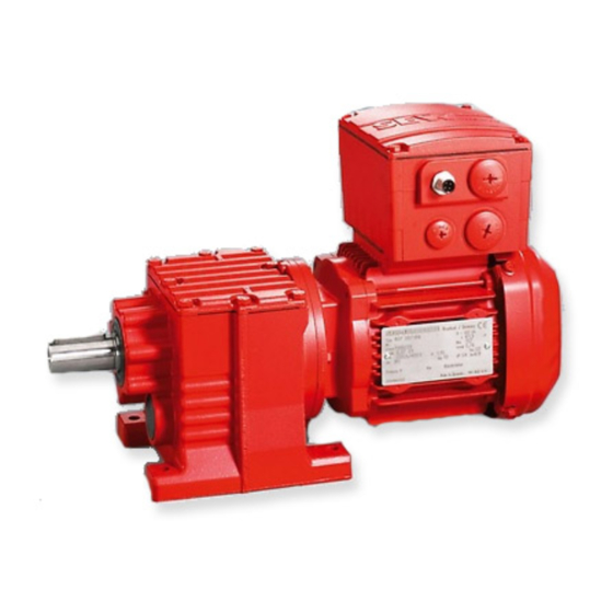
Unit structure MOVI-SWITCH 1E drive Unit structure MOVI- SWITCH 1E drive ® MOVI-SWITCH 1E drive ® The following figure shows a MOVI-SWITCH 1E drive with helical gear unit: 5208932107 ® [1] Connection box with MOVI-SWITCH motor starter [2] Motor [3] Helical gear units ®... -
Page 14: Moviswitch 1E
Unit structure MOVI-SWITCH 1E MOVI- SWITCH 1E ® MOVISWITCH ® The following figure shows the connection box of the MOVI-SWITCH 1E motor starter: 5211396363 [1] 2 x M25 x 1.5 cable glands [2] 2 x M16 x 1.5 cable glands... -
Page 15: Type Designation Of Movi-Switch 1E Drive
Unit structure Type designation of MOVI-SWITCH 1E drive Type designation of MOVI- SWITCH 1E drive ® Type designation of MOVI-SWITCH 1E drive 4.3.1 Nameplate ® The following figure shows a sample nameplate of a MOVI-SWITCH 1E drive: 6306-2Z-C3 6205-2Z-C3 K77/II2GD EDRN100M4BE5/TF/MSW/3D 01.1805414918.0001.12... -
Page 16: Accessory Equipment
Unit structure Accessory equipment Accessory equipment 4.4.1 Mounting variants The following table shows possible output designs: Designation Category Option IEC foot-mounted motor with specification of shaft height 7-series integral motor, as stand-alone motor IEC flange-mounted motor with bore IEC flange-mounted motor with threads General flange-mounted motor (other than IEC) 7-series integral gearmotor with IEC feet, with specification of shaft height if required... -
Page 17: Identification Of Explosion-Protected Drives
Unit structure Identification of explosion-protected drives Identification of explosion-protected drives 4.5.1 Designation according to EU directive At least the following information must be attached visibly and permanently to each unit and protection system. • Name, registered trade name, or registered trade brand, and manufacturer ad- dress. - Page 18 Unit structure Identification of explosion-protected drives Example 2: Operating resources in protection type t for dust explosion protection provided by the enclosure: II 3D Ex tc IIIC T120 °C Dc Example 1 Example 2 Meaning CE marking 0102 Identification number of the notified body (here: PTB), only for category 2 Explosion protection mark Designation ac-...
- Page 19 Unit structure Identification of explosion-protected drives 4.5.3 Identification for potentially explosive dust atmospheres Example Ex tc Symbol for explosion protection with protection type/protection level IIIC Classification of the dust group T120°C Maximum surface temperature in °C Equipment protection level Classification of the dust group In addition, equipment group III has been split up into three subgroups A, B and C de- pending on the type of dust.
-
Page 20: Mechanical Installation
Mechanical installation Installation notes Mechanical installation Installation notes INFORMATION Observe the general safety notes. WARNING ® Improper installation/disassembly of MOVI-SWITCH drives and mount-on compo- nents. Risk of injury. • Adhere to the notes about installation and disassembly. • Before releasing shaft connections, make sure that there are no active torsional moments present (tensions within the system). -
Page 21: Installation Requirements
Mechanical installation Installation requirements Installation requirements Make sure that the following requirements are met before you start installing the unit: • The data on the nameplate of the drive matches the voltage supply system. • The drive is undamaged (no damage caused by transportation or storage). •... -
Page 22: Tightening Torques
Mechanical installation Tightening torques Tightening torques 5.6.1 Terminal box cover Tighten the screws on the terminal box cover using 3.0 Nm working diagonally across. 5213907211 5.6.2 Cable glands Observe the manufacturer's specifications and the follow- ing information for cable glands. • Pay attention to the O-ring on the thread [1]. - Page 23 Mechanical installation Tightening torques 5.6.4 Tightening torques for terminals Use the following tightening torques for terminals during installation: 5211401483 [1] 0.5 – 0.7 Nm [2] 1.2 – 1.6 Nm [3] 0.5 – 0.7 Nm [4] 2.0 – 2.4 Nm [5] 0.3 – 0.5 Nm ®...
-
Page 24: Electrical Installation
Electrical installation Installation notes Electrical installation Installation notes Observe the following information on electrical installation: • Observe the general safety notes. • Comply with all instructions referring to the technical data and the permissible con- ditions where the unit is operated. •... - Page 25 Electrical installation Installation instructions 6.2.3 Permitted cable cross-section Observe the permitted cable cross sections for installation: Power terminals Cores Cores Cores Rigid Flexible Flexible with conductor end sleeve 0.75 mm – 4.0 mm 0.75 mm – 4.0 mm 0.75 mm –...
- Page 26 Electrical installation Installation instructions Connect the conductor Connect the conductor Without pressing the actuation button After pressing the activation button The following conductors can be installed When connecting the following conduct- directly (without tool) up to two cross-sec- ors, you must press the actuation button tion sizes below the nominal cross sec- on top to open the clamping spring: tion:...
- Page 27 Electrical installation Installation instructions 6.2.5 Notes on PE connection WARNING Improperly connecting the PE can cause an electric shock. Severe, fatal injuries • The permitted tightening torque for the retaining screws is 2.0 - 2.4 Nm. • Observe the following notes regarding PE connection. Impermissible assembly Recommendation: Assembly with solid...
- Page 28 Electrical installation Installation instructions 6.2.6 Improving the grounding (EMC), HF grounding For improved, low-impedance grounding at high frequencies, we recommend using the following connections with corrosion protected connection elements: HF grounding is not installed as standard. The HF grounding option can be combined with LF grounding at the terminal box. If you require LF grounding in addition to HF grounding, you can connect the con- ductor to the same point.
- Page 29 Electrical installation Installation instructions 6.2.8 EMC-compliant installation INFORMATION This drive system is not designed for operation on a public low voltage supply system that supplies residential areas. This is a product with restricted availability in accordance with IEC 61800-3. This product may cause EMC interference.
- Page 30 Electrical installation Installation instructions Gasket selection If the motor is operated in environments with high environmental impact, such as in- creased ozone values, the motors can be optionally equipped with gaskets of a higher quality. If you have doubts regarding the stability of the gaskets when subjected to the respective environmental impacts, contact SEW‑EURODRIVE.
-
Page 31: Connecting The Movi-Switch Drive
Electrical installation Connection of MOVI-SWITCH drive Connection of MOVI- SWITCH drive ® Connecting the MOVI-SWITCH drive ® The following figure shows the electrical connection of MOVI-SWITCH 24V RUN OK TF TF F11/F12/F13 5148427531 ..Wired at the factory Higher-level controller Clockwise rotation Independent evaluation unit Counterclockwise ro-... - Page 32 Electrical installation Connection of MOVI-SWITCH drive Description of the control signals Terminal Function Ready signal, DC 24 V 0: Overtemperature or no DC 24 V supply 1: DC 24 V supply is connected and no overtemperature is present ® Operating Instructions – Explosion-Protected MOVI-SWITCH Drives...
-
Page 33: Connecting Movi-Switch ® Drives With Brake
Electrical installation Connection of MOVI-SWITCH drive with brake Connection of MOVI- SWITCH drive with brake ® Connecting MOVI-SWITCH drives with brake ® The following figure shows the electrical connection of MOVI-SWITCH with brake: 24V RUN OK TFTF F11/F12/F13 5150620299 ..Wired at the factory Higher-level controller Clockwise rotation Independent evaluation unit... - Page 34 Electrical installation Connection of MOVI-SWITCH drive with brake Description of the control signals Terminal Function Ready signal, DC 24 V 0: Overtemperature or no DC 24 V supply 1: DC 24 V supply is connected and no overtemperature is present ® Operating Instructions – Explosion-Protected MOVI-SWITCH Drives...
-
Page 35: Startup
Startup General information Startup General information WARNING Electric shock due to incorrect installation. Severe or fatal injuries. • Use switch contacts in utilization category AC-3 according to EN 60947-4-1 for switching the motor. CAUTION The surfaces on the drive can be very hot during operation. Risk of burns. -
Page 36: Startup Of Movi-Switch 1E
Startup Starting up MOVI-SWITCH-1E Starting up MOVI- SWITCH-1E ® Startup of MOVI-SWITCH 7.3.1 Starting the drive ® 1. Check the connection of the MOVI-SWITCH drive. See chapter "Electrical installation". 2. Switch on the line voltage. ® 3. Switch on the MOVI-SWITCH drive with the control signal "RUN" = "1". -
Page 37: Operation
Operation Operating notes Operation Operating notes WARNING Electric shock can be caused by dangerous voltages at the connections, cables and motor terminals. When the device is switched on, dangerous voltages are present at the connections as well as at any connected cables and motor terminals. This also applies, even if the device is blocked and the motor is at a standstill. -
Page 38: Permitted Duty Types
Operation Permitted duty types Permitted duty types 8.2.1 Permitted duty types and protection concept for category 3 motors Design Duty types Addi- Permitted Protection Identification on on nameplate tional duty types against the nameplate name- excessive heating plate – Line operation: Motor circuit breaker –... -
Page 39: Line Operation
Operation Line operation Line operation 8.3.1 Motors in category 3 Continuous duty The motors are designed for continuous duty at a constant power rating (S1) and are marked accordingly. This includes low load startup at a small number of starts per hour that cause hardly any additional heating. - Page 40 Operation Line operation 8.3.2 Calculating the starting frequency You can determine the permitted switching frequency Z of the motor in cycles/hour us- ing the following formula: Z = Z × K × K × K You can determine the factors , and K using the following diagrams: Depending on the...
-
Page 41: Service
Service MOVI-SWITCH® 1E fault list Service MOVI- SWITCH® 1E fault list ® MOVI-SWITCH 1E fault list The following table helps you with troubleshooting: Fault Cause Measure Drive turns in the Incorrect phase se- • Swap 2 phases of the power terminals U1, V1 and W1 wrong direction quence... -
Page 42: Motor Malfunctions
Check the project planning and use a larger motor or special design if necessary. Contact SEW-EURODRIVE. Contact fault on star/delta switch Check the switch, replace if necessary; Check the connections Incorrect direction of... - Page 43 Service Motor malfunctions Fault Possible cause Measure Severe speed loss un- Motor overload Measure power, check project planning and der load use larger motor or reduce load if necessary Voltage drops Check cross section of supply cable, replace with cable of larger cross section if necessary Motor heats up exces- Overload Measure power, check project planning and...
-
Page 44: Sew Service
SEW Service SEW Service If you are unable to rectify a fault, contact SEW‑EURODRIVE Service. For the ad- dresses, refer to www.sew-eurodrive.com. When contacting SEW‑EURODRIVE Service, always specify the following information so that our service personnel can assist you more effectively: •... - Page 45 Service Waste disposal Waste disposal Dispose of the product and all parts separately in accordance with their material struc- ture and the national regulations. Put the product through a recycling process or con- tact a specialist waste disposal company. If possible, divide the product into the follow- ing categories: •...
-
Page 46: Technical Data
Technical data Technical data of MOVI-SWITCH 1E Technical data Technical data of MOVI- SWITCH 1E ® 10.1 Technical data of MOVI-SWITCH ® MOVISWITCH Supply voltages (mo- AC 3 x 380 – 420 V / 415 V / 440 V / 460 V / 480 V / 500 V ± 5 %... -
Page 47: Overhung And Axial Loads For Motor Shaft Ends
Technical data Overhung and axial loads for motor shaft ends ® MOVISWITCH Signal level > U -3 V, when drive is ready for operation 24 V Current for checkback max. 0.65 A, short-circuit proof Signaling function Output for ready signal Checkback signal "Ready for operation" = "1": U >... - Page 48 Technical data Overhung and axial loads for motor shaft ends The customer's overhung load F always has to be less than or equal to the maximum permitted overhung load F from the diagrams: ≤ F The following diagram shows an example of how you can read the maximum over- hung load from the diagram: 1400 1200...
-
Page 49: Permitted Rolling Bearing Types
Technical data Permitted rolling bearing types The diagrams are summarized according to the motor size. The shaft ends available for the respective size are represented in one diagram. The information considers the rated speed n and the higher-level rated torque M continuous duty (S1) of the motor. -
Page 50: Braking Torque Assignment
Technical data Braking torque assignment 10.4 Braking torque assignment Motor type Brake type Braking torque steps EDRN71S BE05 EDRN71M EDRN80MK EDRN80M EDRN90 EDRN100 10.5 Braking work, working air gap, and brake lining carrier thickness If the brake is used in combination with a safety encoder, or if the brake is designed as safety brake, the maximum values for the working air gap and for the braking work un- til maintenance are reduced. -
Page 51: Declaration Of Conformity
Declaration of Conformity Type examination certificate Declaration of Conformity 11.1 Type examination certificate INFORMATION The EU prototype test certificate is provided with the drive. The notified body as well as the technical details are listed in the provided EU prototype test certificate. ®... - Page 52 Declaration of Conformity Type examination certificate EU Declaration of Conformity Translation of the original text 901440312/EN SEW-EURODRIVE GmbH & Co. KG Ernst-Blickle-Straße 42, D-76646 Bruchsal declares under sole responsibility that the following products ® Electronic motor starter of the product seriesMOVI‑SWITCH EDR.../../MSW/3D...
-
Page 53: Index
Index Index Numerical Electrical installation .......... 11 Safety notes ........... 11 24 V supply............ 29 Embedded safety notes......... 7 EMC.............. 28 EMC-compliant installation ........ 29 Additional features.......... 16 Environmental impact .......... 30 Ambient conditions .......... 29 Equipotential bonding .......... 27 Ambient temperature ........... - Page 54 Index Optional equipment .......... 16 Startup ® Other applicable documentation...... 8 MOVI-SWITCH 1EM with binary control.. 36 Output designs ............ 16 Requirements .......... 35 Overhung loads and axial loads Safety notes ........... 12 Overhung loads .......... 47 Supply system cables.......... 24 Torques and duty types........
- Page 60 SEW-EURODRIVE—Driving the world SEW-EURODRIVE GmbH & Co KG Ernst-Blickle-Str. 42 76646 BRUCHSAL GERMANY Tel. +49 7251 75-0 Fax +49 7251 75-1970 sew@sew-eurodrive.com www.sew-eurodrive.com...
Need help?
Do you have a question about the MOVI-SWITCH 1E and is the answer not in the manual?
Questions and answers