
Related Manuals for SEW-Eurodrive MOVI4R-U


Summary of Contents for SEW-Eurodrive MOVI4R-U
- Page 1 *28520688_1218* Drive Technology \ Drive Automation \ System Integration \ Services Operating Instructions Didactics – Electromechanics ® MOVI4R-U Frequency Inverter Module Edition 12/2018 28520688/EN...
- Page 2 SEW-EURODRIVE—Driving the world...
-
Page 3: Table Of Contents
Operation.......................... 23 Important information .................... 23 Operating display (LEDs).................... 24 Manual mode ........................ 25 Service ............................. 27 Electronics Service by SEW‑EURODRIVE.............. 27 Waste disposal...................... 27 Technical data......................... 28 Standards and certifications .................... 29 EC declaration of conformity.................. 29 ® Operating Instructions – MOVI4R-U Frequency Inverter Module... - Page 4 Table of contents Certifications ......................... 29 Address list .......................... 30 Index ............................ 31 ® Operating Instructions – MOVI4R-U Frequency Inverter Module...
-
Page 5: General Information
Type and source of hazard. Possible consequence(s) if disregarded. • Measure(s) to prevent the hazard. Meaning of the hazard symbols The hazard symbols in the safety notes have the following meaning: Hazard symbol Meaning General hazard ® Operating Instructions – MOVI4R-U Frequency Inverter Module... -
Page 6: Decimal Separator In Numerical Values
If required, you can also order prin- ted and bound copies of the documentation from SEW‑EURODRIVE. Product names and trademarks The brands and product names in this documentation are trademarks or registered trademarks of their respective titleholders. ® Operating Instructions – MOVI4R-U Frequency Inverter Module... -
Page 7: Copyright Notice
General information Copyright notice Copyright notice © 2018 SEW‑EURODRIVE. All rights reserved. Unauthorized reproduction, modifica- tion, distribution or any other use of the whole or any part of this documentation is strictly prohibited. ® Operating Instructions – MOVI4R-U Frequency Inverter Module... -
Page 8: Safety Notes
The product is not intended for use in ap- plications (such as lifting applications). The product can be used for operating AC asynchronous motors with squirrel-cage ro- tors. The product is not suited for operating AC synchronous motors. ® Operating Instructions – MOVI4R-U Frequency Inverter Module... -
Page 9: Transport
Ensure that all of the required covers are correctly attached after the electrical installa- tion. The preventive measures and protection devices must comply with the applicable reg- ulations (e.g. EN 60204-1 or EN 61800-5-1). ® Operating Instructions – MOVI4R-U Frequency Inverter Module... -
Page 10: Startup And Operation
Ensure a de-energized state of the product be- fore you start working on it. Ensure a de-energized state for the entire time you work on the product. Repair work may only be carried out by SEW‑EURODRIVE. ® Operating Instructions – MOVI4R-U Frequency Inverter Module... -
Page 11: Device Structure
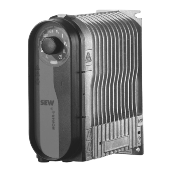
AOUT X1:6 X2:4 DI-03 X1:7 DO-01 X1:4 18014413681566475 X1: Power connection X2: Analog inputs/outputs Main switch (can be locked) X3: Motor connection ® MOVI4R‑U frequency inverter PE: PE connection X1: Digital inputs/outputs ® Operating Instructions – MOVI4R-U Frequency Inverter Module... -
Page 12: Device Components
Quick replacement of the power section and the control plate • The housing can be reused 3.3.2 Motor types SEW-EURODRIVE recommends the following motor type for training on an asynchro- nous motor with simple encoder technology: • DR.. series AC motor Recommendation: Didactics motor assembly DRS71S4 ®... -
Page 13: Installation
Damage due to incorrectly connected digital inputs and digital outputs. Possible damage to property. • Observe the notes regarding connection in the chapter "Electrical installation". 4.1.3 Cable Use the following cables: • Standardized safety cables for use in classrooms or laboratories. ® Operating Instructions – MOVI4R-U Frequency Inverter Module... -
Page 14: Electrical Connections
Interference emission Recommendation: Use shielded motor cables for EMC compliant installation. Electrical connections 4.2.1 Power section connection 230V / 50-60 Hz 15172091659 L: Line connection phase N: Line connection of neutral conductor ® Operating Instructions – MOVI4R-U Frequency Inverter Module... - Page 15 DI-02 X1.6: Digital input DI 02 (direction of rotation) DI-03 X1.7: Digital input DI 03 (setpoint source, fault reset) DO-01 X1.4: DC 24 V output DI-01 switch, latching/spring-return DI-02 switch, latching/spring-return DI-03 switch, latching/spring-return ® Operating Instructions – MOVI4R-U Frequency Inverter Module...
- Page 16 AO REF 10V X2.2: +10 V output AOUT X2.4: Analog output 0 to 10 V 4.2.5 X3: Motor connection 15172094987 Connect the motor at the 4 mm terminals of the motor phases U, V and W. ® Operating Instructions – MOVI4R-U Frequency Inverter Module...
-
Page 17: Startup
> “Installing the control plate” chapters. • Appropriate safety measures prevent the drive from starting up unintentionally. • Appropriate safety measures must be taken to prevent risk of injury or damage to the machine. ® Operating Instructions – MOVI4R-U Frequency Inverter Module... -
Page 18: Preliminary Work
® The following figure shows the control knob of the MOVI4R‑U inverter (size 1): 9282816651 [1] Control knob with pushbutton Startup procedure ® Proceed as follows to start up the MOVI4R‑U inverter: ® Operating Instructions – MOVI4R-U Frequency Inverter Module... - Page 19 Observe the values specified on the motor nameplate when setting the nominal motor power and the nominal motor voltage. ® 1. Check the connection of the MOVI4R-U inverter. ð See chapter "Electrical installation". NOTICE! Loss of guaranteed degree of protection if the inverter is not sealed cor- rectly.
- Page 20 , AI) between which the di- gital input DI 03 has to switch. 2. Select the desired speed setpoint. • When selecting setpoint source n , set speed setpoint n in function menu 1. ® Operating Instructions – MOVI4R-U Frequency Inverter Module...
-
Page 21: Control/Setpoint Source
Maximum speed n • Manual mode activated/inactivated by control knob • Setting in function 5 “Terminal assignment DI03/setpoint source” • Speed setpoint n , fixed speed setpoint n or analog input AI ® Operating Instructions – MOVI4R-U Frequency Inverter Module... - Page 22 Fixed setpoint = 1 – 10 10 – 100% 0 V Analog input AI = 0 – 10 V 0 – 100% +24 V Fixed setpoint = 1 – 10 10 – 100% 1) Setting on the control knob X = any ® Operating Instructions – MOVI4R-U Frequency Inverter Module...
-
Page 23: Operation
10 minutes after disconnection from the supply sys- tem. Severe or fatal injuries. • Wait at least 10 minutes after you switched off the inverter before you start work- ing on it. ® Operating Instructions – MOVI4R-U Frequency Inverter Module... -
Page 24: Operating Display (Leds)
® The status LED shows the current status of the MOVI4R‑U inverter: Status LED Meaning No voltage supply. ® Yellow MOVI4R-U inverter is ready for operation. ® Green MOVI4R-U inverter is enabled. ® Operating Instructions – MOVI4R-U Frequency Inverter Module... -
Page 25: Manual Mode
3. When you turn the control knob to the right, you enable clockwise rotation and in- crease the speed setpoint up to n . When you then turn the control knob to the left again, you decrease the speed setpoint up to 0. DI03 Ι Boost 8896140683 ® Operating Instructions – MOVI4R-U Frequency Inverter Module... - Page 26 Before deactivating manual mode, set the binary signals in such way that the drive is not enabled. • Change the binary signals again only after deactivating manual mode. To deactivate manual mode and to switch to the selection menu, briefly press the con- trol knob. ® Operating Instructions – MOVI4R-U Frequency Inverter Module...
- Page 27 Oil and grease Collect used oil and grease separately according to type. Ensure that the used oil is not mixed with solvent. Dispose of used oil and grease correctly. • Screens • Capacitors ® Operating Instructions – MOVI4R-U Frequency Inverter Module...
-
Page 28: Technical Data
Control voltage analog inputs 0 V – 10 V (setpoint) Line frequency 50 Hz Weight 5 kg Dimensions W × H × D 315 mm × 295 mm × 290 mm For the technical data of the inverter, refer to the system manual. ® Operating Instructions – MOVI4R-U Frequency Inverter Module... -
Page 29: Standards And Certifications
The EC declarations of conformity for the SEW components are listed on the website of SEW‑EURODRIVE with the respective products. Certifications The certificates for the SEW components are listed on the website of SEW‑EURODRIVE with the respective products. ® Operating Instructions – MOVI4R-U Frequency Inverter Module... - Page 30 Graben SEW-EURODRIVE GmbH & Co KG Tel. +49 7251 75-0 Ernst-Blickle-Straße 1 Fax +49 7251-2970 76676 Graben-Neudorf Östringen SEW-EURODRIVE GmbH & Co KG, Werk Tel. +49 7253 9254-0 Östringen Fax +49 7253 9254-90 Franz-Gurk-Straße 2 oestringen@sew-eurodrive.de 76684 Östringen Service Competence Mechanics / SEW-EURODRIVE GmbH &...
- Page 31 Embedded safety notes......... 6 Preliminary information........ 8 Enable with DI01 .......... 21 Structure of embedded........ 6 Structure of the section-related ...... 5 Section-related safety notes ........ 5 Hazard symbols Service .............. 27 Meaning............ 5 ® Operating Instructions – MOVI4R-U Frequency Inverter Module...
- Page 32 Setting parameters ......... 19 Startup procedure........... 18 X1 ................ 15 With different operating modes ...... 19 X2 ................ 16 Structure of the didactics module ...... 11 X3 ................ 16 Target group ............ 8 ® Operating Instructions – MOVI4R-U Frequency Inverter Module...
- Page 36 SEW-EURODRIVE—Driving the world SEW-EURODRIVE GmbH & Co KG Ernst-Blickle-Str. 42 76646 BRUCHSAL GERMANY Tel. +49 7251 75-0 Fax +49 7251 75-1970 sew@sew-eurodrive.com www.sew-eurodrive.com...
Need help?
Do you have a question about the MOVI4R-U and is the answer not in the manual?
Questions and answers