SEW-Eurodrive MOVITRAC LTE-B+ Operating Instructions Manual
System integration
Hide thumbs
Also See for MOVITRAC LTE-B+:
- Manual (48 pages) ,
- Operating instructions manual (76 pages)
Table of Contents
Advertisement
Quick Links
Download this manual
See also:
Manual
Advertisement
Table of Contents

Subscribe to Our Youtube Channel
Related Manuals for SEW-Eurodrive MOVITRAC LTE-B+


Summary of Contents for SEW-Eurodrive MOVITRAC LTE-B+
- Page 1 *24802948_0118* Drive Technology \ Drive Automation \ System Integration \ Services Operating Instructions Frequency Inverters ® MOVITRAC LTE-B+ Edition 01/2018 24802948/EN...
- Page 2 SEW-EURODRIVE—Driving the world...
-
Page 3: Table Of Contents
Contents Contents General information........................ 7 About this documentation .................... 7 Structure of the safety notes ................... 8 1.2.1 Meaning of signal words ................ 8 1.2.2 Structure of section-related safety notes............ 8 1.2.3 Structure of embedded safety notes .............. 8 Rights to claim under limited warranty ................ 8 Exclusion of liability...................... 9 Product names and trademarks.................. 9 Copyright notice ...................... 9... - Page 4 Contents 4.4.7 Opening the front cover................ 27 4.4.8 Connecting and installing the braking resistor .......... 28 4.4.9 Motor temperature protection TF, TH............ 29 4.4.10 Multi-motor drive/group drive ............... 29 4.4.11 Motor cables and fusing ................ 30 4.4.12 Connecting AC brakemotors ................ 30 4.4.13 Information Regarding UL ................
- Page 5 Contents 7.1.1 Structure and settings of process data words .......... 62 7.1.2 Communication example................ 64 7.1.3 Parameter settings for the inverter............... 64 7.1.4 Connecting the signal terminals at the inverter .......... 64 7.1.5 Establishing a CANopen/SBus network ............ 65 ® Connecting a gateway or controller (SBus MOVILINK ) .......... 65 7.2.1...
- Page 6 Contents Protection functions .................... 121 Housing variants and dimensions ................ 121 9.9.1 Housing variants .................. 121 9.9.2 Dimensions of the IP20 housing .............. 122 9.9.3 Dimensions of IP66/NEMA-4X housings (LTE xxx -30 and -40).... 123 9.9.4 Dimension table .................. 124 Address list ........................... 125 Index ............................
-
Page 7: General Information
General information About this documentation General information About this documentation This documentation is an integral part of the product. The documentation is intended for all employees who perform assembly, installation, startup, and service work on the product. Make sure this documentation is accessible and legible. Ensure that persons respons- ible for the machinery and its operation as well as persons who work on the device in- dependently have read through the documentation carefully and understood it. -
Page 8: Structure Of The Safety Notes
General information Structure of the safety notes Structure of the safety notes 1.2.1 Meaning of signal words The following table shows the grading and meaning of the signal words for safety notes. Signal word Meaning Consequences if disregarded DANGER Imminent hazard Severe or fatal injuries. -
Page 9: Exclusion Of Liability
General information Exclusion of liability Exclusion of liability You must comply with the information contained in this documentation to ensure safe operation and to achieve the specified product characteristics and performance fea- tures. SEW-EURODRIVE assumes no liability for injury to persons or damage to equipment or property resulting from non-observance of these operating instructions. -
Page 10: Safety Notes
Safety notes Preliminary information Safety notes Preliminary information The following general safety notes serve the purpose of preventing injury to persons and damage to property. They primarily apply to the use of products described in this documentation. If you use additional components, also observe the relevant warning and safety notes. -
Page 11: Target Group
Safety notes Target group Target group Specialist for Any mechanical work may only be performed by adequately qualified specialists. Spe- mechanical work cialists in the context of this documentation are persons familiar with the design, mechanical installation, troubleshooting, and maintenance of the product who possess the following qualifications: •... -
Page 12: Designated Use
Safety notes Designated use Designated use The product is intended for installation in electrical plants or machines. In case of installation in electrical systems or machines, startup of the product is pro- hibited until it is determined that the machine meets the requirements stipulated in the local laws and directives. -
Page 13: Restrictions Of Use
Safety notes Restrictions of use Protect the product from strong mechanical strain. The product and its mounting parts must never protrude into the path of persons or vehicles. Ensure that components are not deformed and insulation spaces are not changed, particularly during transportation and handling. -
Page 14: Electrical Installation
Safety notes Electrical installation Electrical installation Ensure that all of the required covers are correctly attached after carrying out the elec- trical installation. Make sure that preventive measures and protection devices comply with the applic- able regulations (e.g. EN 60204-1 or EN 61800-5-1). 2.8.1 Required preventive measure Make sure that the product is correctly attached to the ground connection. -
Page 15: Startup/Operation
Safety notes Startup/operation 2.10 Startup/operation Observe the safety notes in the chapters "Startup" and "Operation" in the documenta- tion. Make sure that the present transport protection is removed. Do not deactivate monitoring and protection devices of the machine or system even for a test run. -
Page 16: Device Structure
Device structure Nameplate Device structure Nameplate The following figure shows an example of a nameplate. MCLTEB0015-2B1-4-00 SEW Part No: 18261892 S/Ware : 2.00 Risk of Electric Shock Input Output 200-240 0-250 Power down for 5min before Ø removing F (Hz) 50/60 0-500 cover... -
Page 17: Device Structure Of The Standard Inverter
Device structure Device structure of the standard inverter Device structure of the standard inverter 3.3.1 Inverters with degree of protection IP20/NEMA 1 21435655947 Connecting terminal strip PE, L1/L, L2/N, L3 Help card with terminal assignment and basic parameters Keypad with a 6-digit 7-segment display Control terminal strip RJ45 communication socket Connecting terminal strip PE, +, BR, U, V, W (with BG1 no +- and BR connec-... -
Page 18: Inverters With Degree Of Protection Ip66/Nema 4X
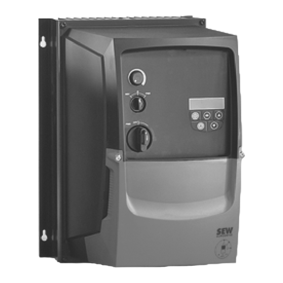
Device structure Device structure of the standard inverter 3.3.2 Inverters with degree of protection IP66/NEMA 4X 21435660939 6-digit 7-segment display Keypad Control terminal strip Connecting terminal strip PE, L1/L, L2/N, L3, +, BR, U, V, W RJ45 communication socket The following items are only present in the device design with switch option. Connection wires of the optional switches Main switch for power supply disconnection Rotary switch for direction of rotation CW/0/CCW... -
Page 19: Installation
Installation General information Installation General information • Carefully check the frequency inverter for damage before installation. • Store the frequency inverter in its original packaging until it is used. The storage location must be clean and dry with an ambient temperature between ‑40 °C and +60 °C. -
Page 20: Permitted Tightening Torques
Installation Permitted tightening torques Permitted tightening torques Tightening torque in Nm Power of the inverters in Control terminals Power terminals Nominal line voltage 115 V 0.37 – 1.1 Nominal line voltage 230 V 0.37 – 5.5 7.5 – 11 15 – 18.5 Nominal line voltage 400 V 0.75 – 11 15 – 22 30 – 37 1) In preparation Mechanical installation 4.3.1 IP20 housing: Installation and installation space... - Page 21 Installation Mechanical installation L1/L L2/N L1/L L2/N 9007211193203851 Size 1) In preparation ® Operating Instructions – MOVITRAC LTE-B+...
-
Page 22: Ip66 Housing: Installation And Control Cabinet Dimensions
Installation Mechanical installation 4.3.2 IP66 housing: Installation and control cabinet dimensions Inverters with IP66 degree of protection can be used indoors. In control cabinets or in field, the following minimum distances must not be underrun. 21436111627 Size INFORMATION If an IP66 inverter is installed in a control cabinet, sufficient control cabinet ventilation must be ensured. -
Page 23: Electrical Installation
Installation Electrical installation Electrical installation WARNING Electric shock due to charged capacitors. Dangerous voltage levels may still be present inside the device and at the terminals up to 10 minutes after disconnection from the power supply. Severe or fatal injuries. • Wait 10 minutes after you have de-energized the inverter and have switched off the line voltage and the DC 24 V voltage. -
Page 24: Before Installation
Installation Electrical installation 4.4.1 Before installation • Make sure that supply voltage, frequency, and number of phases (single- or three- phase) correspond with the nominal values of the inverter on delivery. • A disconnecting switch or similar disconnecting element must be installed between voltage supply and inverter. -
Page 25: Mains Fuses
Installation Electrical installation 30 s 18442995979 4.4.3 Mains fuses Fuse types: • Line protection types in operation classes gL, gG: – Nominal fusing voltage ≥ nominal line voltage – The nominal fusing current must be designed for at least 100% of the inverter nominal input current depending on the inverter utilization. - Page 26 Installation Electrical installation WARNING Danger of electric shock. Dangerous voltage levels may still be present inside the device and at the terminals up to 10 minutes after disconnection from the power supply. Severe or fatal injuries. • Disconnect the frequency inverter from the power supply at least 10 minutes be- fore you screw out the EMC screw.
-
Page 27: Permitted Voltage Supply Systems
Installation Electrical installation 4.4.5 Permitted voltage supply systems • Voltage supply systems with grounded star point Inverters with all degrees of protection are intended for operation on TN and TT systems with directly grounded star point. • Voltage supply systems with non-grounded star point Operation on voltage supply systems with non-grounded star point (for example IT systems) is only permitted for inverters with IP20 degree of protection. -
Page 28: Connecting And Installing The Braking Resistor
Installation Electrical installation 4.4.8 Connecting and installing the braking resistor WARNING Danger of electric shock. The supply cables to the braking resistors carry a high voltage (approx. DC 900 V) during rated operation. Severe or fatal injuries. • Before removing the supply cable, disconnect the inverter from the power supply and wait at least 10 minutes. -
Page 29: Motor Temperature Protection Tf, Th
Installation Electrical installation 4.4.9 Motor temperature protection TF, TH Motors with an internal temperature sensor (TF, TH, or similar) can be connected dir- ectly to the inverter. If the thermal protection is triggered, the inverter displays the error "F-PTC". The following options can be selected for motor protection monitoring: •... -
Page 30: Motor Cables And Fusing
Installation Electrical installation 4.4.11 Motor cables and fusing Comply with the regulations issued by specific countries and for specific machines re- garding fusing and the selection of supply system leads and motor cables. Determine the permitted length of all motor cables connected in parallel as follows: ≤... -
Page 31: Information Regarding Ul
Installation Electrical installation 4.4.13 Information Regarding UL INFORMATION Due to UL requirements, the following chapter is always printed in English independ- ent of the language of the documentation. Ambient Temperature The units in IP20 are suitable for an ambient temperature of 40 °C, max. 50 °C The units in IP66 are suitable for an ambient temperature of 40 °C, max 45 °C. -
Page 32: Electromagnetic Compatibility (Emc)
Installation Electrical installation Branch Circuit Protection 1 × 110 – 115 V devices Devices Fuses or MCB (type B) Max. supply short cir- Max. line voltage cuit current 0004 10 A 0008 20 A 100 kA rms (AC) 115 V 0011 30 A 1 × 200 – 240 V devices Devices Fuses or MCB (type B) Max. - Page 33 Installation Electrical installation Interference immunity With regard to interference immunity, the frequency inverter with an EMC filter meets the limit values defined in the standard EN 61800-3 and can therefore be used for both industrial and domestic (light industrial) applications. Interference emission With regard to interference emission, the inverter meets the EMC limit values of the standard EN 61800-3:2004.
- Page 34 Installation Electrical installation Recommendation for motor shield connection at frequency inverters with IP20 Size 2 and 3 Size 2 Size 3 17304181003 Motor cable Communication cable RJ45 Additional PE connection Control cables The shield plate can be used optionally for size 2 and 3 of the IP20 design. Proceed as follows to adjust: 1.
- Page 35 Installation Electrical installation Recommendation for motor shield connection at frequency inverters with IP66 Install the additional internal shield plate that is included in the delivery of each LTE-B IP66 device at the designated position in the inverter. 9007216558927371 Shield plate Retaining screws Cable gland seals EMC cable gland...
-
Page 36: Overview Of Signal Terminals
Installation Electrical installation 4.4.15 Overview of signal terminals CAUTION Applying voltages of more than 30 V to the signal terminals can damage the control- ler. Possible damage to property. • The voltage applied to the signal terminals must not exceed 30 V. 8 9 10 11 8 9 10 11 27021600697632395... -
Page 37: Communication Socket Rj45
Installation Electrical installation The signal terminal block is equipped with the following signal terminals: Ter- Signal Connection Description minal +24 V Output +24 V: Reference Reference voltage for control of the digital inputs voltage (100 mA max.) DI 1 Digital input 1 Compatible with PLC requirement if 0 V is connec- ted to terminal 7 or 9. -
Page 38: Dc Link Connection, U Connection
Installation Electrical installation Socket at device 9007212770640779 [1] SBus-/CAN bus- [2] SBus+/CAN bus+ [3] 0 V [4] RS485- (engineering) [5] RS485+ (engineering) [6] +24 V (output voltage/backup voltage) [7] RS485- (Modbus RTU) [8] RS485+ (Modbus RTU) 4.4.17 DC link connection, U connection The DC link connection is not possible for LTE-B inverters in size 1 – 3, but it is pos- sible to supply the inverter directly with a DC voltage. - Page 39 Installation Electrical installation L2/N F11/F12/F13 (AC-3) L1 L2 ND LT.. L1' L2' L3' L1 L2 L3 MOVITRAC LT.. *** *** 20268767371 Line contactor between supply system and inverter. Brake Main switch (only for device design IP66/NEMA 4x housing with switch (MC LTE-B..-40)) Connection of BW../BW..T braking resistor Not with 1-phase 230 V...
- Page 40 Installation Electrical installation Brake control F14/F15 F14/F15 F14/F15 (AC-3) (AC-3) (AC-3) (AC-3) (AC-3) white white blue blue white DR/DT/DV: DR/DT/DV: blue Cut-off in the DC Cut-off in the AC circuit and AC circuits 20268785675 Power supply of the brake rectifier, switched simultaneously via K10. Control contactor/control relay, is powered by the internal relay contact [3] of the inverter and supplies the brake rectifier.
-
Page 41: Startup
Startup User interface Startup User interface 5.1.1 Keypads The inverters are equipped with a standard keypad. Standard keypad 9007202188405387 [1] 6-digit 7-segment display [4] Navigate button [2] Start button [5] Up button [3] Stop/Reset button [6] Down button ® Operating Instructions – MOVITRAC LTE-B+... -
Page 42: Resetting Parameters To Default Settings
Startup User interface Operation Both keypads have 5 keys with the following functions: Start [2] • Enable drive • Change direction of rotation • Stop drive Stop [3] • Error acknowledgment Navigate [4] • Switch menu • Save parameter values •... -
Page 43: Software Lt Shell
Startup User interface 5.1.3 Software LT Shell The LT Shell software enables an easy and quick startup of the inverters. It is avail- able for download on the SEW‑EURODRIVE website. After the installation, perform software updates on a regular basis. In combination with the engineering package (cable set C) and the USB11A interface adapter, the inverter can be connected to the software. - Page 44 Startup User interface Connection to LT Shell The connection is performed via an RS485 interface (USB11A + PC engineering ® package) or via Bluetooth (parameter module). LTE-B RS485 9007212384652427 RJ45 to RJ45 cable USB11A RJ adapter (2 x RJ45, 1 x RJ10) [5] Cable USB A-B RJ10 to RJ10 cable LTE-B...
-
Page 45: Movitools ® Motionstudio Engineering Software
Startup User interface ® 5.1.4 MOVITOOLS MotionStudio engineering software The software can be connected to the inverter as follows: • Via an SBus-connection between PC and inverter. A CAN dongle is required. A prefabricated cable is not available and must be manufactured according to the RJ45 assignment and the inverter interface. - Page 46 Startup User interface ® Connection to MOVITOOLS MotionStudio The connection can be set up indirectly via SEW‑EURODRIVE gateway or SEW‑EURODRIVE controller. LTE-B Gateway DFP 21B FAULT ADDRESS 21436360459 Cable USB A-B RJ45 cable with open end USB11A Terminating connector (120 Ω) RJ10 to RJ10 cable Cable splitter LTE-B...
-
Page 47: Automatic Measuring Procedure "Auto Tune
Startup Auto tune Auto tune Automatic measuring procedure "Auto tune" You can start the automatic measuring procedure "Auto tune" manually with the para- meter P-52 after entering the motor data. This process lasts up to 2 minutes depend- ing on the control mode. Do not interrupt the measuring procedure. -
Page 48: Startup For Asynchronous Motors With Lvfc Speed Control
Startup Startup for motors 5.3.2 Startup for asynchronous motors with LVFC speed control 1. Connect the motor to the inverter. During the connection, adhere to the nominal motor voltage. 2. Enter the motor data of the motor nameplate: • P-07 = nominal voltage of the motor •... -
Page 49: Startup Of Control
Startup Startup of control Startup of control WARNING Installing sensors or switches at the terminals may cause an enable signal. The mo- tor may start up automatically. Severe or fatal injuries. • Make sure that no persons are within the reach of moving parts of the system. •... -
Page 50: Keypad Mode (P-12 = 1 Or 2)
Startup Startup of control 5.4.2 Keypad mode (P-12 = 1 or 2) For operation in keypad mode: • Set P-12 to "1" (unidirectional) or "2" (bidirectional). • Connect a jumper or switch between terminals 1 and 2 on the terminal block to en- able the inverter. - Page 51 Startup Startup of control The following figure shows the configuration options for the PI controller. 20290402187 ® Operating Instructions – MOVITRAC LTE-B+...
-
Page 52: Master-Slave Mode (P-12 = 11)
Startup Startup of control 5.4.4 Master-slave mode (P-12 = 11) Master Slave 1 Slave 2 IOIOI IOIOI IOIOI max 63x 16873961867 RJ45 to RJ45 cable Cable splitter The inverter has an integrated master-slave function. The master-slave communication is obtained via a special protocol. In this case, the inverter communicates via the RS485 engineering interface. -
Page 53: Fieldbus Mode (P-12 = 3, 4, 5, 6, 7 Or 8)
Startup Fire mode/emergency mode Configuring the slave inverters • Each connected slave must have a unique slave communication address that is set with the inverter address P-36 level 1. You can assign slave addresses from 2 to 63. Set: • P-12 = 11 (control signal source) •... -
Page 54: Operation At 87 Hz Characteristic (50 Hz Motors)
Startup Operation at 87 Hz characteristic (50 Hz motors) Operation at 87 Hz characteristic (50 Hz motors) The V/f ratio remains the same at 87 Hz operation. However, higher power and speeds are generated which causes a higher current flow. 400 V 230 V 87 Hz 50 Hz 9007206616827403... -
Page 55: Fans And Pumps
Startup Fans and pumps Fans and pumps The following functions are available for applications with pumps or fans: • Voltage increase / boost (P-11) • Adjustment of the V/f characteristic curve (P-28, P-29) • Energy-saving function (P-06) • Flying start function (P-33) •... -
Page 56: Control Signal Source 3-Wire Control
Startup 3-wire control 5.9.1 Control signal source 3-wire control DI 1 +24 V DI 1 DI 2 DI 3 DI 3 +10 V AI 1 DI 2 AI 1 9007218080811659 DI 1 CW/stop CW rotation DI 3 CCW/stop CCW rotation DI 2 Enable/stop Ramp up (P-03) AI 1... -
Page 57: Operation
Operation Status of the inverter Operation Status of the inverter 6.1.1 Static inverter status The following table shows the status messages for a non-enabled inverter. Message Description StoP Power section of inverter disabled. This message is displayed when the motor is at standstill and no error is present. -
Page 58: Troubleshooting
Operation Troubleshooting Troubleshooting Symptom Cause and solution Overload or overcurrent error of the Check the star/delta terminal connection in the motor. The nominal unloaded motor during acceleration operating voltage of motor and inverter must match. The delta con- nection always yields the lower voltage of a multi-voltage motor. Overload or overcurrent –... -
Page 59: Error Codes
Operation Error codes Error codes Error message Error code CANopen Explanation Solution Inverter display P00-28 status word if Emer- error history Bit5 = 1 gency Code Inverter MotionStu display dio cod- ing dec 4-20 F 0x71 0x1012 Signal loss 4 – •... - Page 60 Operation Error codes Error message Error code CANopen Explanation Solution Inverter display P00-28 status word if Emer- error history Bit5 = 1 gency Code Inverter MotionStu display dio cod- ing dec 0x01 0x2303 Short-term over- Fault during stop procedure: current at the in- Check for premature brake application.
- Page 61 Operation Error codes Error message Error code CANopen Explanation Solution Inverter display P00-28 status word if Emer- error history Bit5 = 1 gency Code Inverter MotionStu display dio cod- ing dec OL-br 0x04 0x1002 Braking resistor The software detected an overload at the braking resistor overload and switches off to protect the resistor.
-
Page 62: Fieldbus Mode
Fieldbus mode General information Fieldbus mode General information 7.1.1 Structure and settings of process data words The process data assignment is set as standard. The structure of process data words is identical for SBus/Modbus RTU/CANopen, as well as with inserted communication card. High byte Low byte 15 – 8... - Page 63 Fieldbus mode General information Process input words Description Settings Byte Status word 0 Output stage enable 0: Locked Low byte 1: Approved Inverter ready 0: Not ready for operation 1: Ready PO data enabled 1 if P-12 = 3 or 4 3 – 4 Reserved Fault/warning...
-
Page 64: Communication Example
Fieldbus mode General information 7.1.2 Communication example The following information is sent to the inverter if • The digital inputs have been configured and wired properly to enable the inverter. Description Value Description Control word 0x0000 Stop along the second Deceleration ramp (P-24). 0x0001 Coasting 0x0002... -
Page 65: Establishing A Canopen/Sbus Network
Fieldbus mode Connecting a gateway or a controller (SBus MOVILINK) 7.1.5 Establishing a CANopen/SBus network A CAN network as depicted in the figure below should always have a linear bus struc- ture without stub lines [1] or only with very short ones [2]. The network must have ex- actly one terminating resistor R = 120 Ω... -
Page 66: Electrical Installation
Fieldbus mode Connecting a gateway or a controller (SBus MOVILINK) 7.2.2 Electrical installation ® Connecting gateway and MOVI‑PLC DFP 21B FAULT ADDRESS IOIOI IOIOI IOIOI max. 8 20240906123 Bus connection Splitters Gateway, e.g. DFx/UOH Connection cable Connection cable Y connector with terminating resistor INFORMATION The terminating connector [F] is equipped with 2 terminating resistors and therefore establishes the terminating connection to CAN/SBus and Modbus RTU. -
Page 67: Startup At Gateway
Fieldbus mode Modbus RTU 7.2.3 Startup at gateway • Connect the gateway as described in chapter "Electrical installation" (→ 2 66). • Reset all settings of the gateway to the factory setting. • If required, set all connected inverters to SBus MOVILINK® mode as described in chapter "Parameter settings for the inverter" ... -
Page 68: Register Allocation Of The Process Data Words
Fieldbus mode Modbus RTU 7.3.3 Register allocation of the process data words The process data words are allocated to the Modbus registers shown in the table. The table shows the default allocation of process data words. All other registers are usually allocated in such a way that they correspond to the parameter number (101 = P-01). -
Page 69: Data Flow Example
Fieldbus mode Modbus RTU 7.3.4 Data flow example In this example, the following parameters are read by the controller (PLC address base = 1): • P-07 (rated motor voltage, Modbus register 135) • P-08 (rated motor current, Modbus register 136). Request master → slave (Tx) Reading register Address... -
Page 70: Canopen
Fieldbus mode CANopen Start address Register start address =0x0001 = 1 (first register to be written on = 2 PA2) Information 0700 (setpoint speed) 2 × CRC bytes CRC_high, CRC_low CANopen The inverters support communication via CANopen. For using CANopen, configure the inverter as described in chapter "Parameter settings for the inverter" (→ 2 64). -
Page 71: Cob Ids And Functions In The Inverter
Fieldbus mode CANopen 7.4.3 COB IDs and functions in the inverter The CANopen profile provides the following COB ID (Communication Object Identifier) and functions. Messages and COB IDs Type COB ID Function 000h Network management Sync 080h Synchronous message with dynamically configurable COB ID Emergency 080h + device address Emergency message with dynamically configurable COB ID... -
Page 72: Default Allocation Plan Of Process Data Objects (Pdo)
Fieldbus mode CANopen 7.4.5 Default allocation plan of process data objects (PDO) The following table shows the default mapping of the PDOs: PDO default mapping Object no. Mapped Length Mapping with default setting Transmission object type Rx PDO1 2010h Unsigned 16 PO1 control word 2012h Integer 16... -
Page 73: Data Flow Example
Fieldbus mode CANopen 7.4.6 Data flow example Process data communication example with default setting: Word 1 Word 2 Word 3 Word 4 COB ID DB Byte 1 Byte 2 Byte 3 Byte 4 Byte 5 Byte 6 Byte 5 Byte 6 Description 0x701 "00"... -
Page 74: Table Of Canopen-Specific Objects
Fieldbus mode CANopen 7.4.7 Table of CANopen-specific objects CANopen-specific objects Index Sub index Function Access Type PDO map Default value 1000h Device type Unsigned 32 1001h Error register Unsigned 8 1002h Manufacturer status register Unsigned 16 1005h COB-ID Sync Unsigned 32 00000080h 1008h Manufacturer device name... -
Page 75: Table Of Manufacturer-Specific Objects
Fieldbus mode CANopen CANopen-specific objects Index Sub index Function Access Type PDO map Default value 1A01h TX PDO2 mapping / no. of entries Unsigned 8 TX PDO2 1 mapped object Unsigned 32 21180010h TX PDO2 2 mapped object Unsigned 32 21190010h TX PDO2 3 mapped object... -
Page 76: Parameters
Parameters Overview of parameters Parameters Overview of parameters 8.1.1 Parameters for realtime monitoring (read only) Parameter group 0 gives access to internal inverter parameters for monitoring pur- poses. These parameters cannot be changed. Parameter group 0 is visible when P-14 is set to "101". Access to parameter group 0 •... - Page 77 Parameters Overview of parameters Description of parameter group 0 Parameter CANopen/ Modbus Description Display range Explanation SBus index register Value of analog in- Index value 1000 = 100% ≙ max. input voltage or P00-01 11210 0 – 100% put 1 current. Value of analog in- Index value 1000 = 100% ≙ max. input voltage or P00-02 11211 0 – 100%...
- Page 78 Parameters Overview of parameters Parameter CANopen/ Modbus Description Display range Explanation SBus index register Total Time in which the inverter was operated at > 60 °C Value 1: Hours runtime > 60 °C P00-24 11237 – 11238 – Value 2: Minutes, (control electron- seconds ics) Rotor speed (cal- Speed display in Hz when P-10 = 0, else in min P00-25 11291...
-
Page 79: Standard Parameters
Parameters Overview of parameters Parameter CANopen/ Modbus Description Display range Explanation SBus index register Display value for Current value of the latest oscilloscope measure- Channel 1 P00-48 11226 – 11227 18, 19 channel 1 and 2 in- ment. Unit refers to the set size Channel 2 ternal oscilloscope Display value for... -
Page 80: Advanced Parameters
Parameters Overview of parameters 8.1.3 Advanced parameters Parameter CANopen/ Modbus Description Setting range SBus index register Factory setting P-15 11031 Digital input function selection (→ 2 86) 0 − 13 P-16 11064 Analog input 1 format (→ 2 91) U0 – 10 b0 – 10 A0 – 20 t4 – 20 r4 – 30 t20 – 4 r20 – 4 P-17 11003 PWM switching frequency (→ 2 92) - Page 81 Parameters Overview of parameters Parameter CANopen/ Modbus Description Setting range SBus index register Factory setting U0 – 10 A0 – 20 t4 – 20 P-47 11067 Analog input 2 format (→ 2 106) r4 – 30 t20 – 4 r20 – 4 Ptc – th P-48 11061 Standby mode (→ 2 106) 0.0 – 25 s P-49 PI control difference wake-up level 11087 0.0 – 5.0 – 100% (→ 2 106)
-
Page 82: Advanced Parameter Description
Parameters Advanced parameter description Advanced parameter description 8.2.1 Basic parameters P-01 Maximum speed Setting range: P-02 – 50.0 Hz – 5 × P-09 (maximum 500 Hz) Specifies the upper limit for the frequency (speed) that can be applied to the motor in any operating mode. This parameter is displayed in Hz when factory settings are used or when the parameter for the rated motor speed (P1-10) is set to zero. - Page 83 Parameters Advanced parameter description P-05 Stop mode Defines the delay behavior of the drive for normal operation and power failure. Setting range: 0 – 2 In the event of power failure: • 0: Operation continues • 1: Motor coasts to a halt •...
- Page 84 Parameters Advanced parameter description P-08 Rated motor current Setting range: 20 – 100% of the inverter output current. Is given as absolute value in ampere. Specifies the rated current of the motor connected to the inverter (according to the motor nameplate). This allows the inverter to match its internal thermal motor protec- tion (I x t protection) to the motor.
- Page 85 Parameters Advanced parameter description P-11 Voltage increase, boost Setting range: 0 – 25% of the max. output voltage. Resolution 0.1% • Size 1: max. 25% • Size 2: max. 20% • Size 3: max. 15% • Size 4: max. 10% Increases the output voltage of the frequency inverter by a scalable value (in case of low speed) to obtain a higher motor torque generation in this speed range.
-
Page 86: Extended Parameterization
Parameters Advanced parameter description P-13 Reserved Parameter reserved P-14 Extended parameter access Setting range: 0 – 9999 This parameter allows access to all parameters. Access is possible when the following values are valid. • 0: P-01 – P-15 (basis parameter) • 101: P-01 – P-60 (extended parameters) The password (101) is defined in parameter P-37 and can be changed in a user-... - Page 87 Parameters Advanced parameter description Terminal mode When parameter P-12 = 0 (terminal mode), the following table applies: Digital input 3/ Analog input 1/ P-15 Digital input 1 Digital input 2 Comments Analog input 2 Digital input 4 0: Stop 0: CW rotation 0: Analog speed setpoint Analog speed set- –...
- Page 88 Parameters Advanced parameter description Keypad mode INFORMATION The enable/start behavior always depends on the setting made in P-31. When parameter P-12 = 1 or 2 (keypad mode), the following table applies. P-15 Digital input 1 Digital input 2 Digital input 3/ Analog input 1/ Comments Up key Down key...
- Page 89 Parameters Advanced parameter description SBus, CANopen, Modbus-RTU, and slave control mode INFORMATION The enable/start behavior always depends on the setting made in P-31 The hardware enable is the prerequisite for the fieldbus enable. The setpoint switchover (DI2) functions with SBus only in combination with the hard- ware enable (DI1) and fieldbus enable.
- Page 90 Parameters Advanced parameter description PI controller control mode P-15 Digital input 1 Digital input 2 Digital input 3/ Analog input 1/ Comments Analog input 2 Digital input 4 0, 2, 0: Stop 0: PI controller See comments See comments The setpoint and actual value 9 – 12 1: Enable + start 1: Fixed setpoint speed 1...
- Page 91 Parameters Advanced parameter description P-16 Analog input 1 format Setting range: • 0: U0 – 10 V/unipolar voltage input • 1: b0 – 10 V/bipolar voltage input -10 V – 10 V • 2: A0 – 20 mA/current input • 3: t4 – 20 mA/current input • 4: r4 – 20 mA/current input • 5: t20 – 4 mA/current input • 6: r20 – 4 mA/current input "t.."...
- Page 92 Parameters Advanced parameter description P-17 PWM switching frequency Setting range: 2 – 4 – 16 kHz (performance-related) Specifies the pulse width modulated switching frequency. A higher switching fre- quency means less motor noise, but also higher losses in the output stage. The maxi- mum switching frequency depends on the inverter power rating. The inverter reduces the switching frequency automatically depending on the following conditions: •...
- Page 93 Parameters Advanced parameter description P-18 User relay output function selection Setting range: 0 – 1 – 8 The function of the relay output can be selected according to the table below. If a relay is controlled depending on a limit value, it reacts according to the curve in P-50 (→ 2 106).
- Page 94 Parameters Advanced parameter description P-19 Limit value for relay/analog output Setting range: 0.0 – 100.0 – 200.0% Specifies the limit values for P-18 and P-25. P-20 Fixed setpoint speed 1 Setting range: -P-01 – 5.0 Hz – P-01 P-21 Fixed setpoint speed 2 Setting range: -P-01 – 25.0 Hz – P-01 P-22 Fixed setpoint speed 3 Setting range: -P-01 – 40.0 Hz – P-01 P-23 Fixed setpoint speed 4...
- Page 95 Parameters Advanced parameter description P-25 Analog output function selection Setting range: 0 – 8 – 10 The function of the analog output/digital output can be selected according to the table below. If P-25 is parameterized as a digital output, it behaves according to the curve in P-50 (→ 2 106) Set-...
- Page 96 Parameters Advanced parameter description In some applications, mechanical resonance vibrations may occur in certain speed ranges. This may have a negative effect on the machine behavior. The speed skip function can be used to skip the interfering speed range. The drive speed performs the depicted hysteresis with the ramps specified in P-03 and P-04.
- Page 97 Parameters Advanced parameter description P-28/P-29 V/f characteristic curve adjustment Setting range P-28: 0 – P-07 in volts Setting P-29: 0 – P-09 in Hertz The voltage/frequency characteristic curve determines the voltage level applied to the motor at a given frequency. Parameters P-29 P-28 let the user change the V/f characteristic curve if required.
- Page 98 Parameters Advanced parameter description P-30 Start mode selection The selection of the start mode defines the inverter behavior with reference to the en- able digital input and configures the automatic restart function. Setting range: Edge-r – Auto-0 – Auto-5 Edge-r • Edge-r: After activation or resetting of an error (Reset), the frequency inverter does not start automatically, even if an enable signal is still present at the relevant digital input.
- Page 99 Parameters Advanced parameter description Setting range: 0 – 1 – 7 Switchover behavior when the setpoint source switches to keypad mode: The motor speed continues to run at the minimum speed from P-02. The motor speed changes to the last keypad speed set. The motor speed continues to run at the minimum speed from P-02. The motor speed changes to the last keypad speed set.
- Page 100 Parameters Advanced parameter description P-32 DC hold function The parameter is divided into two levels and only works in combination with settings in P-58 and P-59. Level 1: Current holding time Setting range: 0.0 – 25 s The set value determines the duration of the direct current holding function. Level 2: Current holding mode Setting range: 0 – 2 The set value determines the function of the direct current holding function.
- Page 101 Parameters Advanced parameter description P-35 Analog input 1/slave scaling Setting range: See 0.0 – 100.0 – 2000% Slave scaling (P-12 = 11) P-35 = (n ) × 100% slave master Analog input scaling (P-12 ≠ 11) The analog input can be scaled using the parameter P-35/P-39. The parameters can be calculated with the following formula depending on the desired characteristic curve: Calculation of the scaling parameters: P-01 = Amount from the greater value of n and n...
- Page 102 Parameters Advanced parameter description Example with calculation in Hz (P-10 = 0) [n] = Hz P (AI |n ) = (80|50) [AI] = % -100 P (AI |n ) = (0|-50) 22712753931 P-01 = 50 Hz, since |n | > |n P-02 = 0 Hz P-16 = -10 – 10 V, since n < 0 − − P-35 = 10000 50 80 0...
- Page 103 Parameters Advanced parameter description P-36 Fieldbus settings The parameter is divided into three levels and acts depending on the setting in P-12. Level 1: Inverter address Setting range: 1 - 63 This parameter is used to set the inverter address for SBus, Modbus, fieldbus and master/slave.
- Page 104 Parameters Advanced parameter description P-37 Extended parameter access code definition Setting range: 0 – 101 – 9999 The set value determines the code for the full parameter access in P-14. P-38 Parameter lock Locking parameters means that no parameters can be changed (indicated by "L"). •...
- Page 105 Parameters Advanced parameter description P-42 PI proportional gain Setting range: 0.0 – 1.0 – 30.0 PI controller proportional gain. Higher values result in a greater change of the inverter output frequency as response to minor changes of the feedback signal. If the value is too high, it can cause instability.
- Page 106 Parameters Advanced parameter description P-47 Analog input 2 format Setting range: • 0: U0 – 10 V/unipolar voltage input • 1: A0 – 20 mA/current input • 2: t4 – 20 mA/current input • 3: r4 – 20 mA/current input • 4: t20 – 4 mA/current input • 5: r20 – 4 mA/current input • 6: Ptc-th/motor thermistor input "t.."...
- Page 107 Parameters Advanced parameter description P-51 Selection of motor control procedure Setting range: 0 – 1 – 5 • 0: LVFC (light vector flux control) Vector speed control for induction motors with calculated rotor speed feedback control. Field-oriented control algorithms are used for motor speed control. As the calculated rotor speed is used to internally close the speed loop, this control mode provides a simple closed loop control system without physical encoder.
- Page 108 Parameters Advanced parameter description P-53 Controller parameter The parameter is divided into two levels. Level 1: Speed controller proportional gain Setting range: 0 – 250% Defines the proportional gain for the speed controller. Higher values provide for better output frequency regulation and response. If the value is too high, it can cause in- stability or even overcurrent errors.
- Page 109 Parameters Advanced parameter description P-54 Current limit Setting range: 0.1 – 150 – 175% The set value refers to the nominal motor current P-08 and determines the maximum current limit of the inverter. NOTICE Possible damage to the frequency inverter when the internal parameters are set in- correctly Damage to property •...
- Page 110 Parameters Advanced parameter description P-58 DC braking speed Setting range: 0.0 – P-01 This parameter defines the limit speed starting at which DC braking becomes active. This parameter only acts together with P-32 (level 1 and 2) and P-59. P-59 Current strength of DC holding function Setting range: 0 – 20.0 – 100% This parameter determines the percentage current strength depending on P-08.
-
Page 111: Technical Data
Technical data Markings Technical data Markings The following table lists all markings that can be given on a nameplate or attached to the motor and an explanation of what they mean. Marking Meaning CE mark to state compliance with the Low Voltage Directive 2014/35/EU. EU directive 2011/65/EU (RoHS) serves for limiting the use of hazardous substances in electric and electronic equipment. -
Page 112: Output Power And Current Carrying Capacity Without Emc Filter
Technical data Output power and current carrying capacity without EMC filter Output power and current carrying capacity without EMC filter The "Horsepower" (HP) data is specified as follows. • 200 – 240 V devices: NEC2002, table 430-150, 230 V • 380 – 480 V devices: NEC2002, table 430-150, 460 V 9.3.1 1-phase system AC 115 V for 3-phase AC 230 V motors (voltage doubler) ®... -
Page 113: Output Power And Current Carrying Capacity With Emc Filter
Technical data Output power and current carrying capacity with EMC filter Output power and current carrying capacity with EMC filter The "Horsepower" (HP) data is specified as follows. • 200 – 240 V devices: NEC2002, table 430-150, 230 V • 380 – 480 V devices: NEC2002, table 430-150, 460 V 9.4.1 1-phase system AC 230 V for 3-phase AC 230 V motors ®... -
Page 114: 3-Phase System Ac 230 V For 3-Phase Ac 230 V Motors
Technical data Output power and current carrying capacity with EMC filter 9.4.2 3-phase system AC 230 V for 3-phase AC 230 V motors Power 1.5 – 4 kW ® MOVITRAC LTE-B+ – EMC filter class C2 according to EN 61800-3 Power in kW IP20/NEMA 1 MC LTE-B.. 0015-2A3-4-00 0022-2A3-4-00 0040-2A3-4-00 Part number 18261884... - Page 115 Technical data Output power and current carrying capacity with EMC filter Power 5.5 – 18.5 kW ® MOVITRAC LTE-B+ – EMC filter class C2 according to EN 61800-3 (in preparation) Power in kW 18.5 IP20/NEMA 1 MC LTE-B.. 0055-2A3-4-00 0075-2A3-4-00 0110-2A3-4-00 0150-2A3-4-00 0185-2A3-4-00 Part number 18267416 18267424 18267432 18267440 18267459...
-
Page 116: 3-Phase System Ac 400 V For 3-Phase Ac 400 V Motors
Technical data Output power and current carrying capacity with EMC filter 9.4.3 3-phase system AC 400 V for 3-phase AC 400 V motors Power 0.75 – 4 kW ® MOVITRAC LTE-B+ – EMC filter class C2 according to EN 61800-3 Power in kW 0.75 IP20/NEMA 1 MC LTE-B.. 0008-5A3-1-00 0015-5A3-1-00 0015-5A3-4-00 0022-5A3-4-00... - Page 117 Technical data Output power and current carrying capacity with EMC filter Power 5.5 – 11 kW ® MOVITRAC LTE-B+ – EMC filter class C2 according to EN 61800-3 Power in kW IP20/NEMA 1 MC LTE-B.. 0055-5A3-4-00 0075-5A3-4-00 0110-5A3-4-00 Part number 18262074 18262090 18262112 IP66/NEMA 4X housing without switches MC LTE-B..
- Page 118 Technical data Output power and current carrying capacity with EMC filter Power 15 = 22 kW ® MOVITRAC LTE-B+ – EMC filter class C2 according to EN 61800-3 (in preparation) Power in kW 18.5 IP20/NEMA 1 MC LTE-B.. 0150-5A3-4-00 0185-5A3-4-00 0220-5A3-4-00 Part number 18262147 18262155 18262163 INPUT Nominal line voltage V 3 × AC 380 – 480 ±10% line...
- Page 119 Technical data Output power and current carrying capacity with EMC filter Power 30 – 37 kW ® MOVITRAC LTE-B+ – EMC filter class C2 according to EN 61800-3 (in preparation) Power in kW IP20/NEMA 1 MC LTE-B.. 0300-5A3-4-00 0370-5A3-4-00 Part number 18267394 18267408 INPUT Nominal line voltage V 3 × AC 380 – 480 ±10% line cording to EN 50160...
-
Page 120: Input Voltage Ranges
Technical data Input voltage ranges Input voltage ranges Depending on the model and the nominal power, the frequency inverters are designed for direct connection to the following voltage sources: ® MOVITRAC LTE-B Nominal voltage Connection Rated frequency type 110 – 115 V ± 10% 1-phase 200 –... -
Page 121: Protection Functions
Technical data Protection functions Protection functions • Short circuit output, phase-phase, phase-ground • Overload protection of the inverter • Overload protection of the motor • Overvoltage shutdown • Undervoltage shutdown • Shutdown caused by overtemperature • Shutdown caused by undertemperature Housing variants and dimensions 9.9.1 Housing variants... -
Page 122: Dimensions Of The Ip20 Housing
Technical data Housing variants and dimensions 9.9.2 Dimensions of the IP20 housing L1/L L2/N 9007204991655691 Dimensions Unit Size 1 Size 2 Size 3 Size 4 Size 5 Height (A) Width (B) Depth (C) 123.5 Mass 18.1 23.5 25.5 11.5 Recommended screws 4 ×... -
Page 123: Dimensions Of Ip66/Nema-4X Housings (Lte Xxx -30 And -40)
Technical data Housing variants and dimensions 9.9.3 Dimensions of IP66/NEMA-4X housings (LTE xxx -30 and -40) 9007205178204043 ® Operating Instructions – MOVITRAC LTE-B+... -
Page 124: Dimension Table
Technical data Housing variants and dimensions 9.9.4 Dimension table Dimensions Size 1 Size 2 Size 3 Height (A) Width (B) Depth (C) 186.5 Mass 148.5 197.5 6.25 6.75 28.5 33.4 251.5 Recommended screw size 4 × M4 4 × M4 4 ×... -
Page 125: Address List
Fax +213 21 8222-84 Bellevue http://www.reducom-dz.com 16200 El Harrach Alger info@reducom-dz.com Argentina Assembly Buenos Aires SEW EURODRIVE ARGENTINA S.A. Tel. +54 3327 4572-84 Sales Ruta Panamericana Km 37.5, Lote 35 Fax +54 3327 4572-21 (B1619IEA) Centro Industrial Garín http://www.sew-eurodrive.com.ar Prov. de Buenos Aires sewar@sew-eurodrive.com.ar... - Page 126 Address list Cameroon Sales Douala SEW-EURODRIVE S.A.R.L. Tel. +237 233 39 02 10 Ancienne Route Bonabéri Fax +237 233 39 02 10 P.O. Box sew@sew-eurodrive-cm B.P 8674 Douala-Cameroun Canada Assembly Toronto SEW-EURODRIVE CO. OF CANADA LTD. Tel. +1 905 791-1553 Sales 210 Walker Drive Fax +1 905 791-2999...
- Page 127 Address list Colombia Assembly Bogota SEW-EURODRIVE COLOMBIA LTDA. Tel. +57 1 54750-50 Sales Calle 17 No. 132-18 Fax +57 1 54750-44 Service Interior 2 Bodega 6, Manzana B http://www.sew-eurodrive.com.co Santafé de Bogotá sew@sew-eurodrive.com.co Croatia Sales Zagreb KOMPEKS d. o. o. Tel.
- Page 128 Address list France Lyon SEW-USOCOME Tel. +33 4 74 99 60 00 75 rue Antoine Condorcet Fax +33 4 74 99 60 15 38090 Vaulx-Milieu Nantes SEW-USOCOME Tel. +33 2 40 78 42 00 Parc d’activités de la forêt Fax +33 2 40 78 42 20 4 rue des Fontenelles 44140 Le Bignon Paris...
- Page 129 Address list Germany Würzburg SEW-EURODRIVE GmbH & Co KG Tel. +49 931 27886-60 Nürnbergerstraße 118 Fax +49 931 27886-66 97076 Würzburg-Lengfeld dc-wuerzburg@sew-eurodrive.de Drive Service Hotline / 24 Hour Service 0 800 SEWHELP 0 800 7394357 Great Britain Assembly Normanton SEW-EURODRIVE Ltd. Tel.
- Page 130 Address list Indonesia Surabaya PT. TRIAGRI JAYA ABADI Tel. +62 31 5990128 Jl. Sukosemolo No. 63, Galaxi Bumi Permai Fax +62 31 5962666 G6 No. 11 sales@triagri.co.id Surabaya 60111 http://www.triagri.co.id Surabaya CV. Multi Mas Tel. +62 31 5458589 Jl. Raden Saleh 43A Kav. 18 Fax +62 31 5317220 Surabaya 60174 sianhwa@sby.centrin.net.id...
- Page 131 Address list Lebanon Sales (Lebanon) Beirut Gabriel Acar & Fils sarl Tel. +961 1 510 532 B. P. 80484 Fax +961 1 494 971 Bourj Hammoud, Beirut ssacar@inco.com.lb Sales (Jordan, Kuwait , Beirut Middle East Drives S.A.L. (offshore) Tel. +961 1 494 786 Saudi Arabia, Syria) Sin El Fil.
- Page 132 Fax +595 21 3285539 Departamento Central sewpy@sew-eurodrive.com.py Fernando de la Mora, Barrio Bernardino Peru Assembly Lima SEW EURODRIVE DEL PERU S.A.C. Tel. +51 1 3495280 Sales Los Calderos, 120-124 Fax +51 1 3493002 Service Urbanizacion Industrial Vulcano, ATE, Lima http://www.sew-eurodrive.com.pe sewperu@sew-eurodrive.com.pe...
- Page 133 Address list Sambia representation: South Africa Senegal Sales Dakar SENEMECA Tel. +221 338 494 770 Mécanique Générale Fax +221 338 494 771 Km 8, Route de Rufisque http://www.senemeca.com B.P. 3251, Dakar senemeca@senemeca.sn Serbia Sales Belgrade DIPAR d.o.o. Tel. +381 11 347 3244 / +381 11 288 0393 Ustanicka 128a Fax +381 11 347 1337 PC Košum, IV floor...
- Page 134 Address list South Korea Busan SEW-EURODRIVE KOREA CO., LTD. Tel. +82 51 832-0204 28, Noksansandan 262-ro 50beon-gil, Fax +82 51 832-0230 Gangseo-gu, Busan, Zip 618-820 Spain Assembly Bilbao SEW-EURODRIVE ESPAÑA, S.L. Tel. +34 94 43184-70 Sales Parque Tecnológico, Edificio, 302 http://www.sew-eurodrive.es Service 48170 Zamudio (Vizcaya)
- Page 135 Address list United Arab Emirates Sales Dubai SEW-EURODRIVE FZE Tel. +971 (0)4 8806461 Service PO Box 263835 Fax +971 (0)4 8806464 Office No. S3A1SR03 http://www.sew-eurodrive.ae Jebel Ali Free Zone – South, info@sew-eurodrive.ae Dubai, United Arab Emirates Ukraine Assembly Dnipropetrovsk ООО «СЕВ-Евродрайв» Tel.
-
Page 136: Index
Index Index Numerical Before installation........... 24 Safety notes ........... 14 3-wire control ............ 55 Electromagnetic compatibility ...... 32 87 Hz characteristic (50 Hz motors) .... 54 Interference emission ........ 33 Interference immunity........ 33 Embedded safety notes......... 8 AC brakemotors, connection ....... 30 EMC standards for interference emission .. - Page 137 Index P-20 Fixed setpoint speed 1........ 94 P-21 Fixed setpoint speed 2........ 94 Line contactors ............ 24 P-22 Fixed setpoint speed 3........ 94 LT Shell software.......... 43 P-23 Fixed setpoint speed 4........ 94 LTX encoder module ........... 27 P-24 Second deceleration ramp, rapid stop ramp 94 P-25 Analog output function selection ....
- Page 138 Index Real time monitoring ........ 76 Fault codes............. 59 Parameter settings for the inverter ...... 64 Fault history............ 58 Parameters for realtime monitoring ..... 76 Signal words in the safety notes...... 8 PI controller mode, startup ........ 50 Slip compensation ......... 47, 84 Port Standard parameters...........
- Page 144 SEW-EURODRIVE—Driving the world SEW-EURODRIVE GmbH & Co KG Ernst-Blickle-Str. 42 76646 BRUCHSAL GERMANY Tel. +49 7251 75-0 Fax +49 7251 75-1970 sew@sew-eurodrive.com www.sew-eurodrive.com...
Need help?
Do you have a question about the MOVITRAC LTE-B+ and is the answer not in the manual?
Questions and answers