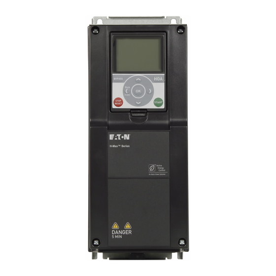
Eaton H-max Series Installation Manual

Eaton H-max Series Installation Manual

Variable frequency drive
Hide thumbs Also See for H-max Series:
Table of Contents

Advertisement

H-Max™ Series Variable Frequency Drive
Installation Manual
Effective May 2017
Supersedes September 2011

Advertisement

Table of Contents
loading

Summary of Contents for Eaton H-max Series

  • Page 1 H-Max™ Series Variable Frequency Drive Installation Manual Effective May 2017 Supersedes September 2011...
  • Page 3 OBLIGATION OF EATON. THE CONTENTS OF THIS DOCUMENT SHALL NOT BECOME PART OF OR MODIFY ANY CONTRACT BETWEEN THE PARTIES. In no event will Eaton be responsible to the purchaser or user in contract, in tort (including negligence), strict liability or...
  • Page 4 H-Max Series Variable Frequency Drive Support Services The goal of Eaton is to ensure your greatest possible satisfaction with the operation of our products. We are dedicated to providing fast, friendly, and accurate assistance. That is why we offer you so many ways to get the support you need. Whether it’s by phone, fax, or e-mail, you can access Eaton’s support information 24 hours a day, seven days a week.
  • Page 5: Table Of Contents

    Dimension Drawings..........H-Max Series Variable Frequency Drive MN04008005E—May 2017 www.eaton.com...
  • Page 6 Figure 21. Wiring the VFD ..........Figure 22. H-Max Series Variable Frequency Drive ......
  • Page 7 Table 6. NEMA Type 1/IP21 or NEMA Type 12/IP54 ......Table 7 . H-Max Series Variable Frequency Drive Option Boards ....
  • Page 8 Desktop or portable units must only be operated and from the power supply. Due to the charge in the controlled in enclosed housings capacitors, these parts may still be live after disconnection. Fit appropriate warning signs H-Max Series Variable Frequency Drive MN04008005E—May 2017 www.eaton.com...
  • Page 9: Definitions And Symbols

    Be sure equipment is properly grounded. Wear safety glasses whenever working on electronic controllers or A changeover between the frequency inverter and the input rotating machinery. supply must take place in a voltage-free state. H-Max Series Variable Frequency Drive MN04008005E—May 2017 www.eaton.com...
  • Page 10 Only use cables, protective switches, and contactors that feature the indicated permissible nominal current value. Before connecting the AC drive to mains make sure that the EMC protection class settings of the drive are appropriately made. viii H-Max Series Variable Frequency Drive MN04008005E—May 2017 www.eaton.com...
  • Page 11: Engineering

    Motor protection; thermistor Cable lengths, motor cables, shielding (EMC) Motor and application, parallel operation of multiple motors L1 L2 L3 PE on a frequency inverter, bypass circuit; DC braking PE U V W H-Max Series Variable Frequency Drive MN04008005E—May 2017 www.eaton.com...
  • Page 12: Electrical Power Network

    Electrical Power Network Input Connection and Configuration Input Voltage and Frequency The H-Max series frequency inverters can be connected and The standardized input voltages (IEC 60038, VDE017-1) for operated with all control-point grounded AC power networks energy suppliers (EVU) guarantee the following conditions at (see IEC 60364 for more information).
  • Page 13 Compensation on the power supply side is not required for the direct connection of greater power ratings, deviations H-Max series frequency inverters. From the AC power from the ideal voltage form and asymmetrical voltages can supply network, they take on very little reactive power of the be caused in three-phase AC power networks.
  • Page 14: Safety And Switching

    ● height of the pulse frequency (switching frequency of the ● inverter) design of the noise filter ● grounding measures at the site of the motor ● H-Max Series Variable Frequency Drive MN04008005E—May 2017 www.eaton.com...
  • Page 15: Emc Measures

    Figure 3. EMC Environment and Category Public Medium-Voltage Supply Grid Public Industry Industry Low-Voltage Measuring Supply Grid Grid 1 Grid 2 Point Category C1 Category C1/C2 Category C3/C4 Category C3/C4 Enviroment Enviroment H-Max Series Variable Frequency Drive MN04008005E—May 2017 www.eaton.com...
  • Page 16: Motor And Application

    AC-3. Selecting the motor contactor is done according to the rated operational current of the motor to be connected. H-Max Series Variable Frequency Drive MN04008005E—May 2017 www.eaton.com...
  • Page 17: Figure 5. Example Of A Motor Ratings Plate

    Motor frequency 50 Hz 50 Hz 87 Hz Notes Star connection: 400V, 50 Hz. Delta connection: 230V, 50 Hz. Delta connection: 400V, 87 Hz. Note the permitted limit values of the motor. H-Max Series Variable Frequency Drive MN04008005E—May 2017 www.eaton.com...
  • Page 18: Figure 8. Bypass Motor Control (Example)

    I> I> I> apparatus for EX areas L1 L2L3 U V W Item Number Description Input/bypass contactor Output contactor H-Max Series Variable Frequency Drive MN04008005E—May 2017 www.eaton.com...
  • Page 19: System Overview

    AC network into a DC voltage. This DC voltage is used to generate a three-phase AC voltage with variable frequency and assigned amplitude values for the variable speed control of three-phase asynchronous motors. H-Max Series Variable Frequency Drive MN04008005E—May 2017 www.eaton.com...
  • Page 20: Figure 11. Block Diagram, Elements Of H-Max Frequency Inverters

    HMX32: 0.55–90 kW (230V, 50 Hz) or 0.75–125 hp (230V, 60 Hz) HMX34: 1.1–160 kW (400V, 50 Hz) or 1.5–250 hp (460V, 60 Hz) HMX35: 3–200 hp (600V, 60 Hz) DC link—chokes, to minimize current harmonics H-Max Series Variable Frequency Drive MN04008005E—May 2017 www.eaton.com...
  • Page 21: Selection Criteria

    (for example, 3 AC~400V) Rated motor current (guide value, dependent on the circuit ● type and the supply voltage) Load torque (quadratic, constant) ● Starting torque ● Ambient temperature (rated value 122°F [50°C]) ● H-Max Series Variable Frequency Drive MN04008005E—May 2017 www.eaton.com...
  • Page 22: Proper Use

    (bypass) ● Observe the technical data and connection requirements. For additional information, refer to the equipment nameplate or label at the frequency inverter, and the documentation. Any other usage constitutes improper use. H-Max Series Variable Frequency Drive MN04008005E—May 2017 www.eaton.com...
  • Page 23: Storage

    This information can also be found on the cover of the control terminals. Information concerning the guarantee can be found in the Eaton General Terms and Conditions of Sale. H-Max Series Variable Frequency Drive MN04008005E—May 2017 www.eaton.com...
  • Page 24: H-Max Series Overview

    Make sure that the part number indicated on the nameplate corresponds with the catalog number on your order. The H-Max Series VFD has met a stringent series of factory If shipping damage has occurred, please contact and file a quality requirements before shipment. It is possible that claim with the carrier involved immediately.
  • Page 25: Figure 13. Rating Plate

    OUTPUT: 3~ AC, 0 -Uin, 0-320 Hz, 12A Power (IL): 5.5kW: 400V/7.5HP: 480V Firmware: LISTED Application: ® 9D42 Marks: POWER CONVERSION EQUIPMENT Style: H34AG01221EB EATON CORPORATION Frequency inverter Frequenzumrichter Convertiesseur des fréquences 1 234567 890128 07W09 U.S. Carton Label H-Max Series Variable Frequency Drive MN04008005E—May 2017 www.eaton.com...
  • Page 26: Catalog Number Selection

    Battery included in all drives for real-time clock. Three year lifetime. Keypad kit includes HOA bypass. Keypad kit includes HOA, back reset for Europe application. EMI/RFI filters included. DC link choke included. H-Max Series Variable Frequency Drive MN04008005E—May 2017 www.eaton.com...
  • Page 27: Power Ratings And Product Selection

    12.5 10.9 HMX32AG0122_-N 16.1 15.2 12.5 HMX32AG0182_-N 21.7 HMX32AG0242_-N 27.7 HMX32AG0312_-N 43.8 HMX32AG0482_-N HMX32AG0622_-N 18.5 HMX32AG0752_-N 82.1 HMX32AG0882_-N HMX32AG1052_-N HMX32AG1402_-N HMX32AG1702_-N HMX32AG2052_-N HMX32AG2612_-N HMX32AG3102_-N Note For sizing reference, full-load motor running currents—UL508C. H-Max Series Variable Frequency Drive MN04008005E—May 2017 www.eaton.com...
  • Page 28: Table 5. Nema Type 1/Ip21 Or Nema Type 12/Ip54

    21.3 HMX34AG0232_-N 28.4 HMX34AG0312_-N 36.7 18.5 HMX34AG0382_-N 43.6 HMX34AG0462_-N 58.2 HMX34AG0612_-N 67.5 HMX34AG0722_-N 85.3 HMX34AG0872_-N 100.6 HMX34AG1052_-N 139.4 HMX34AG1402_-N 166.5 HMX34AG1702_-N HMX34AG2052_-N HMX34AG2612_-N HMX34AG3102_-N Note For sizing reference, full-load motor running currents—UL508C. H-Max Series Variable Frequency Drive MN04008005E—May 2017 www.eaton.com...
  • Page 29: Table 6. Nema Type 1/Ip21 Or Nema Type 12/Ip54

    53.8 HMX35AG0522_-N 62.2 HMX35AG0622_-N HMX35AG0802_-N HMX35AG1002_-N HMX35AG1252_-N HMX35AG1442_-N HMX35AG2082_-N Table 7. H-Max Series Variable Frequency Drive Option Boards Assigned to Option Board Control Part Number Module Slot: Description XMX-IO-B1-A D or E Expanded 6 digital output—two outputs are programmable as digital inputs or outputs...
  • Page 30: Electrical Installation

    (intermediate circuit capacitor discharging time). Pay attention to hazard warnings! DANGER 5 MIN Note: Complete the following steps with the specified tools and without using force. H-Max Series Variable Frequency Drive MN04008005E—May 2017 www.eaton.com...
  • Page 31: Installation Requirements

    This chapter contains all of the information required to properly When mounting one unit above the other the lower unit air install and prepare the H-Max Series VFD for operation. The outlet must be directed away from the inlet air used by the contents are listed to serve as a list of tasks needed to upper one.
  • Page 32: Figure 17. Mounting Space

    Installation Requirements Mounting dimensions: Refer to Page 23 for drive dimensions ● Figure 17. Mounting Space Table 8. Space Requirements for Mounting the H-Max Series VFD and Airflow Frame Line Cooling Air Size Voltage hp (VT) Amperes in (mm) in (mm)
  • Page 33: Nema Type 1/12 Open Drives (1-250 Hp)

    600V 15–30 — 18–34 230V 25–40 18.5–30 75–105 10.49 25.98 25.39 24.29 9.06 7.48 7.48 82.6 (37.5) (266.5) (660) (645) (617) (237) (190) (190) 480V 50–75 37–55 72–105 600V 40–60 — 41–62 H-Max Series Variable Frequency Drive MN04008005E—May 2017 www.eaton.com...
  • Page 34: Figure 19. Mounting Drive Dimensions-Fs8 And Fs9

    600V 75–125 — 80–125 230V 100–125 75–90 261–310 14.63 33.09 31.89 31.89 18.90 15.75 1.57 238.1 (108) (372) (1150.4) (810) (810) (480) (400) (40) 480V 200–250 132–160 261–310 600V 150–200 — 144–208 H-Max Series Variable Frequency Drive MN04008005E—May 2017 www.eaton.com...
  • Page 35: Power Wiring Selection

    High Speed J (UL and CSA) ● aR (UL recognized, IEC 60269-4) ● gS (IEC 60269-4) ● Consult with Eaton Electrical for further information on fusing requirements. H-Max Series Variable Frequency Drive MN04008005E—May 2017 www.eaton.com...
  • Page 36: Figure 20. Input Power And Motor Cable Stripping Lengths

    1.10 9.45 1.10 9.45 1.10 9.45 1.10 9.45 (28) (240) (28) (240) (28) (240) (28) (240) 1.10 11.61 1.10 11.61 1.10 11.61 1.10 11.61 (28) (295) (28) (295) (28) (295) (28) (295) H-Max Series Variable Frequency Drive MN04008005E—May 2017 www.eaton.com...
  • Page 37: Cable Routing

    Page 25. Figure 21. Wiring the VFD H-Max *Dedicated Dedicated Ground Ground U/T 1 V/T 2 W/T 3 Incoming Optional Utility Motor Power *Conduit Only Does Not Represent Ground. H-Max Series Variable Frequency Drive MN04008005E—May 2017 www.eaton.com...
  • Page 38 Pass motor, input power wires/cables through base wiring plate. If shielded cable is used, connect the shields of input power and motor cables shields to ground. H-Max Series Variable Frequency Drive MN04008005E—May 2017 www.eaton.com...
  • Page 39 Control Wiring Wire the control terminals following the details for the specific option boards shown on the following pages. Note: For ease of access, the board terminals blocks can be unplugged for wiring. H-Max Series Variable Frequency Drive MN04008005E—May 2017 www.eaton.com...
  • Page 40 DATA- RS-485 DATA- Programmable BACnet, Modbus, FLN, N2 DATA+ RS-485 DATA+ Relay Board 1 Slot B Default Signal RO1 Bypass Run 24 Vdc/8A 250 Vac/8A 125 Vdc/0.4A RO2 Drive Run RO3 Fault H-Max Series Variable Frequency Drive MN04008005E—May 2017 www.eaton.com...
  • Page 41: Control Board

    Installation Requirements Control Board The main H-Max Series VFD consists of a main control board, control I/O connections block and two slots for extra option boards. This main control board launched March 2017. Serial Numbers after C171201265 were manufactured with this main control board. All units manufactured prior shipped with an old style control board.
  • Page 42: Figure 23. Dip Switch Functionality

    A. The voltage signal (U), 0–10 V input B. The current signal (I), 0–20 mA input C. OFF D. ON E. The RS-485 bus termination Table 16. DIP Switch DIP Switch Default Position RS-485 bus termination H-Max Series Variable Frequency Drive MN04008005E—May 2017 www.eaton.com...
  • Page 43: Figure 24. Digital Input Ground Isolation

    BR-1/2 AA or a Vitzrocell SB-AA02. Install the battery on the left side of the control panel. The battery will last approximately 10 years. See more about the functions of the RTC in the Application Manual. H-Max Series Variable Frequency Drive MN04008005E—May 2017 www.eaton.com...
  • Page 44: Emc Installation

    Avoid using painted surfaces (anodized, chromized). An voltage source (PES). overview of all EMC measures is provided in the figure on Page 35. H-Max Series Variable Frequency Drive MN04008005E—May 2017 www.eaton.com...
  • Page 45: Figure 25. Emc-Compliant Setup (Example: H-Max)

    Connect the cable shielding in the output of the frequency inverter with a large surface area contact to the ground potential (PES). Large-area cable shield contacts with motor. Large-area earth connection of all metallic parts. H-Max Series Variable Frequency Drive MN04008005E—May 2017 www.eaton.com...
  • Page 46: Figure 26. Cable Description

    ÖCuY -0 or similar Figure 26. Cable Description PE Conductor PE Conductor and Shield Shield Note 360° earthing of the shield with cable glands in motor end needed for EMC Level C2. H-Max Series Variable Frequency Drive MN04008005E—May 2017 www.eaton.com...
  • Page 47: Figure 27. Locations Of The Emc-Jumpers In Frames Fs4 To Fs6

    Remove the main cover of the AC drive (see figure below) series drives. and locate the jumpers connecting the built-in RFI-filters to ground. See figure below. Figure 27. Locations of the EMC-Jumpers in Frames FS4 to FS6 H-Max Series Variable Frequency Drive MN04008005E—May 2017 www.eaton.com...
  • Page 48: Figure 28. Three-Phase Input Connection

    U/T1, V/T2, W/T3: Connection terminals for the ● three-phase line to the AC motor (output, frequency inverter) PE: connection for protective ground (reference ● potential). PES with mounted cable routing plate for shielded cables H-Max Series Variable Frequency Drive MN04008005E—May 2017 www.eaton.com...
  • Page 49: Figure 31. Removing The Jumper, Fs5 As Example

    Figure 31. Removing the Jumper, FS5 as Example Remove the main cover of the AC drive and locate the jumper. FS8 only: Push down the grounding arm. See figure below. Figure 32. Grounding Bar Location, FS8 H-Max Series Variable Frequency Drive MN04008005E—May 2017 www.eaton.com...
  • Page 50: Figure 33. Removing The Emc Jumper, Fs7 And Fs8

    Detach the jumper and re-fix the box cover. See figure below. by undoing the M4 screw. See figure below. Figure 33. Removing the EMC Jumper, FS7 and FS8 Figure 34. Detaching the DC Grounding Bus Bar from Frame, FS7 H-Max Series Variable Frequency Drive MN04008005E—May 2017 www.eaton.com...
  • Page 51: Figure 35. Molex Connector Placement, Fs9

    (see figure below) and note the date. Unless already done, attach the sticker close to the name plate of the AC drive. Figure 37. Product Modified Sticker Product modified Date: Date: EMC-level modified C1->C4 DDMMYY Date: H-Max Series Variable Frequency Drive MN04008005E—May 2017 www.eaton.com...
  • Page 52: Checking The Cable And Motor Insulation

    Check the input power cable insulation as follows: Disconnect the input power cable from terminals L1, L2 ● and L3 of the H-Max Series drive and from the utility line feeder Measure the insulation resistance of the input power ●...
  • Page 53: Technical Data

    380–480V: 4500m (TN and IT systems) 525–600V: 2000m (TN and IT systems, no corner grounding) Voltage for I/O signals: Up to 2000m: Allowed up to 240V 2000–4500m: Allowed up to 120V Corner-grounding: Up to 2000m only H-Max Series Variable Frequency Drive MN04008005E—May 2017 www.eaton.com...
  • Page 54: Table 18. H-Max Technical Data

    Supply voltage 600V: Trip limit 527V Earth fault protection Mains supervision Motor phase supervision Overcurrent protection Unit overtemperature protection Motor overload protection Motor stall protection Motor underload protection Short-circuit protection of 24V and 10V reference voltages H-Max Series Variable Frequency Drive MN04008005E—May 2017 www.eaton.com...
  • Page 55: Table 19. Standard I/O Board

    Selection V/mA with DIP switches Short-circuit protected 24V auxiliary input voltage Can be used as external power backup for the control unit RS-485 Differential receiver/transmitter Set bus terminal with DIP switches RS-485 H-Max Series Variable Frequency Drive MN04008005E—May 2017 www.eaton.com...
  • Page 56: Table 20. Relay Board 1

    This is to prevent welding on the relay contacts. Refer to standard EN60204-1, section 7 .2.9. Relay board with two change-over contact (SPDT) relays and a PTC thermistor input. 5.5 mm isolation between channels. H-Max Series Variable Frequency Drive MN04008005E—May 2017 www.eaton.com...
  • Page 57: Cable Power And Motor Wiring Guidelines

    If power cubes are used, a UL recognized Type T fuse is recommended. Based on maximum environment of 104°F (40°C). If bypass is used, a UL recognized Type T fuse is recommended. H-Max Series Variable Frequency Drive MN04008005E—May 2017 www.eaton.com...
  • Page 58: Table 23. North America Cable And Fuse Sizes-380-480 Vac Ratings

    If power cubes are used, a UL recognized Type T fuse is recommended. Based on maximum environment of 104°F (40°C). If bypass is used, a UL recognized Type T fuse is recommended. H-Max Series Variable Frequency Drive MN04008005E—May 2017 www.eaton.com...
  • Page 59: Table 24. North America Cable And Fuse Sizes-525-600 Vac Ratings

    1 AWG–350 kcmil 1 AWG–350 kcmil 1 AWG–350 kcmil 1 AWG–350 kcmil 1 AWG–350 kcmil 1 AWG–350 kcmil 1 AWG–350 kcmil 1 AWG–350 kcmil 300 kcmil 300 kcmil 1 AWG–350 kcmil 1 AWG–350 kcmil H-Max Series Variable Frequency Drive MN04008005E—May 2017 www.eaton.com...
  • Page 60: Table 25. International Cable And Fuse Sizes 380-480 Vac Ratings

    If power cubes are used, a UL recognized Type T fuse is recommended. Based on maximum environment of 104°F (40°C). If bypass is used, a UL recognized Type T fuse is recommended H-Max Series Variable Frequency Drive MN04008005E—May 2017 www.eaton.com...
  • Page 61: Dimension Drawings

    Appendix C Appendix C Dimension Drawings Figure 38. FS4 Dimension Drawing H-Max Series Variable Frequency Drive MN04008005E—May 2017 www.eaton.com...
  • Page 62: Figure 39. Fs4 Dimension Drawing Flange Mount

    Appendix C Figure 39. FS4 Dimension Drawing Flange Mount H-Max Series Variable Frequency Drive MN04008005E—May 2017 www.eaton.com...
  • Page 63: Figure 40. Fs5 Dimension Drawing

    Appendix C Figure 40. FS5 Dimension Drawing H-Max Series Variable Frequency Drive MN04008005E—May 2017 www.eaton.com...
  • Page 64: Figure 41. Fs5 Dimension Drawing Flange Mount

    Appendix C Figure 41. FS5 Dimension Drawing Flange Mount H-Max Series Variable Frequency Drive MN04008005E—May 2017 www.eaton.com...
  • Page 65: Figure 42. Fs6 Dimension Drawing

    Appendix C Figure 42. FS6 Dimension Drawing H-Max Series Variable Frequency Drive MN04008005E—May 2017 www.eaton.com...
  • Page 66: Figure 43. Fs6 Dimension Drawing Flange Mount

    Appendix C Figure 43. FS6 Dimension Drawing Flange Mount H-Max Series Variable Frequency Drive MN04008005E—May 2017 www.eaton.com...
  • Page 67: Figure 44. Fs7 Dimension Drawing

    Appendix C Figure 44. FS7 Dimension Drawing H-Max Series Variable Frequency Drive MN04008005E—May 2017 www.eaton.com...
  • Page 68: Figure 45. Fs7 Dimension Drawing Flange Mount

    Appendix C Figure 45. FS7 Dimension Drawing Flange Mount H-Max Series Variable Frequency Drive MN04008005E—May 2017 www.eaton.com...
  • Page 69: Figure 46. Fs8 Dimension Drawing Ip00

    Appendix C Figure 46. FS8 Dimension Drawing IP00 H-Max Series Variable Frequency Drive MN04008005E—May 2017 www.eaton.com...
  • Page 70: Figure 47. Fs8 Dimension Drawing Ip2154 Flange Mount

    Appendix C Figure 47. FS8 Dimension Drawing IP2154 Flange Mount H-Max Series Variable Frequency Drive MN04008005E—May 2017 www.eaton.com...
  • Page 71: Figure 48. Fs8 Dimension Drawing Flange Mount

    Appendix C Figure 48. FS8 Dimension Drawing Flange Mount H-Max Series Variable Frequency Drive MN04008005E—May 2017 www.eaton.com...
  • Page 72: Figure 49. Fs9 Dimension Drawing

    Appendix C Figure 49. FS9 Dimension Drawing H-Max Series Variable Frequency Drive MN04008005E—May 2017 www.eaton.com...
  • Page 73: Figure 50. Fs9 Dimension Drawing Ip2154

    Appendix C Figure 50. FS9 Dimension Drawing IP2154 H-Max Series Variable Frequency Drive MN04008005E—May 2017 www.eaton.com...
  • Page 74: Figure 51. Fs9 Dimension Drawing Flange Mount

    Appendix C Figure 51. FS9 Dimension Drawing Flange Mount H-Max Series Variable Frequency Drive MN04008005E—May 2017 www.eaton.com...
  • Page 76 At Eaton, we believe that power is a fundamental part of just about everything people do. Technology, transportation, energy and infrastructure-these are things the world relies on every day. That’s why Eaton is dedicated to helping our customers find new ways to manage electrical, hydraulic and mechanical power more efficiently, safely and sustainably.

This manual is also suitable for:

Hmx32ag3d721-nHmx32ag01121-nHmx32ag4d821-nHmx32ag01221-nHmx32ag01821-nHmx32ag02421-n ... Show all

Table of Contents