
Related Manuals for Eaton 12-110-1250y


Summary of Contents for Eaton 12-110-1250y
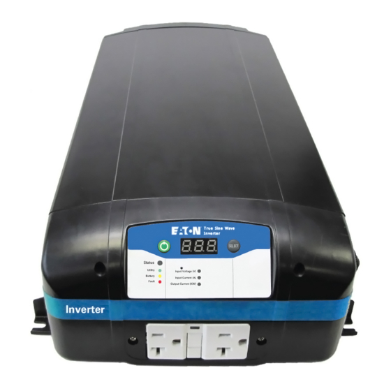
- Page 1 True Sine Wave Inverter Eaton 1250W / 1500W / 1800W Inverter Operation and Installation Guide...
- Page 2 CONTENTS OF THIS DOCUMENT SHALL NOT BECOME PART OF OR MODIFY ANY CONTRACT BETWEEN THE PARTIES. In no event will Eaton be responsible to the purchaser or user in contract, in tort (including negligence), strict liability or other- wise for any special, indirect, incidental or consequential damage or loss whatsoever, including but not limited to damage or...
-
Page 3: Table Of Contents
Test installation ............26 IM SP180164 /Rev D www.eaton.com Eaton 1250W / 1500W / 1800W Inverter Operation and Installation Guide... - Page 4 Personal precautions when working with batteries WARNING WARNING Limitations on use - The Eaton Inverter is not to be connected to life support devices. Risk of electrical shock, burn from high short-circuit current, fire or explosion from vented gases. WARNING •...
-
Page 5: Introduction
Introduction The Eaton Inverter is designed to create 1.8kW of pure sine wave 115VAC 60Hz power from a 12V battery source. The units low THD (<2.5% typical) can power sophisticated electronics that may not work with modified sine wave inverters. Unit also has high surge capability to power up hard to start loads like power tools, refrigerators or pumps. -
Page 6: Configuration
Press the SELECT button once more. Screen displays the battery type for charging: Fl = Fixed; FLo = Flooded; gEL = Gel, Ag = AGM. ote: If model equipped with AC bypass switch, selections will vary while in bypass mode. IM SP180164 / Rev D www.eaton.com Eaton 1250W / 1500W / 1800W Inverter Operation and Installation Guide... -
Page 7: Setting Battery Type And Charge Current
Confirm the new setting by not touching the inverter for approximately 5 seconds to return to inverter setting display mode. Press SELECT button multiple times to confirm new setting(s). Unit performance can be optimized using Table 2. IM SP180164 / Rev D www.eaton.com Eaton 1250W / 1500W / 1800W Inverter Operation and Installation Guide... - Page 8 Press the SELECT button until “11.8” (or current setting) is displayed. Press and hold the POWER button for 5 seconds. Press SELECT button to toggle between the three voltage shutdown settings: • 11.8 • 12.2 • 10.5 IM SP180164 / Rev D www.eaton.com Eaton 1250W / 1500W / 1800W Inverter Operation and Installation Guide...
- Page 9 Confirm the new setting by not touching the inverter for approximately 5 seconds to return to inverter setting display mode. Press SELECT button multiple times to confirm new setting(s). IM SP180164 / Rev D www.eaton.com Eaton 1250W / 1500W / 1800W Inverter Operation and Installation Guide...
-
Page 10: Fault Codes And Troubleshooting
AC Overload or Short Circuit shutdown error when utility is available. The supplemental protector or the branch protection specified in the Installation Guide should be open under bypass short circuit output condition. IM SP180164 / Rev D www.eaton.com Eaton 1250W / 1500W / 1800W Inverter Operation and Installation Guide... - Page 11 • Charger DC output protection: Reverse polarity on DC terminal will open the input fuses in the Eaton Inverter. This damage is not covered under warranty. Table 5.
-
Page 12: Troubleshooting
This could be due to an overload condition in shore power mode. Reduce the load and unit will return to normal operation IM SP180164 / Rev D www.eaton.com Eaton 1250W / 1500W / 1800W Inverter Operation and Installation Guide... -
Page 13: Charger And Ac Transfer
Audio alarm: Beep @ 1 Hz and AC charger is latched off following 15 minute delay • Bypass mode is available • To reset error code, remove AC Input and cycle unit off and on until reset IM SP180164 / Rev D www.eaton.com Eaton 1250W / 1500W / 1800W Inverter Operation and Installation Guide... -
Page 14: Specifications
Specifications Specifications Appendix A is the location for product performance information and electrical specifications for the 1800W Eaton Inverter. Important: Specs are subject to changes without notice. Technical specifications Table 8. Input Voltages High 12.5Vdc 13.0Vdc 13.0Vdc Nominal DC input Input voltage operating range 10.5-16.0Vdc... -
Page 15: Installation
Charge current maximum set charge current setting to compensate for an external DC load on demand. Maximum charge current setting Float current Time IM SP180164 / Rev D www.eaton.com Eaton 1250W / 1500W / 1800W Inverter Operation and Installation Guide... -
Page 16: Installation
Mark the standard. 47 CFR FCC Part 15, Subpart B, Comply with the requirements of FCC Mark Class B 2016 the standard. IM SP180164 / Rev D www.eaton.com Eaton 1250W / 1500W / 1800W Inverter Operation and Installation Guide... -
Page 17: Installation
Non-E models: 6.8kG [15.0lb], E models: 5.3kG [11.7lb] Torque DC input cable fasteners to 12.2 -13.6 Nm Torque chassis ground cable fastener to 6.6 – 7 .3 Nm IM SP180164 / Rev D www.eaton.com Eaton 1250W / 1500W / 1800W Inverter Operation and Installation Guide... -
Page 18: Installation
Prior to engaging in any service, all AC and DC power sources need to be disabled. • Follow proper cable routing and strain relief guidelines. IM SP180164 / Rev D www.eaton.com Eaton 1250W / 1500W / 1800W Inverter Operation and Installation Guide... -
Page 19: Installation Types And Definitions
See “AC Output Neutral Bonding” on next page for further information on bonding relay operation. ote: The grid power source utilized must be branch breaker or branch fuse protected at 30A maximum. IM SP180164 / Rev D www.eaton.com Eaton 1250W / 1500W / 1800W Inverter Operation and Installation Guide... - Page 20 The inverter sources input power from a 12VDC deep cycle or dual purpose batteries. The inverter converts the 12VDC input power to 115VAC output. IM SP180164 / Rev D www.eaton.com Eaton 1250W / 1500W / 1800W Inverter Operation and Installation Guide...
-
Page 21: Choose A Location For Inverter Mounting
Batteries: Never allow battery acid to come in contact with the inverter or the wiring to and from the devices. It is also important to be aware of the corrosive gases that may be coming into contact with the inverter. IM SP180164 / Rev D www.eaton.com Eaton 1250W / 1500W / 1800W Inverter Operation and Installation Guide... -
Page 22: Mount The Inverter
Fire hazard - Improper grounding may result in a fire hazard. It is crucial to never operate the inverter without ensuring the equipment is properly connected to ground. IM SP180164 / Rev D www.eaton.com Eaton 1250W / 1500W / 1800W Inverter Operation and Installation Guide... -
Page 23: Connect The Ac Input Wires (Optional For Ac Input)
In this case, the main AC panel must not install a permanent neutral to ground bond. IM SP180164 / Rev D www.eaton.com Eaton 1250W / 1500W / 1800W Inverter Operation and Installation Guide... - Page 24 Strip enough of the input cable jacket as to expose the three wires, about 2 inches (50mm). Strip approximately 3/8 inches (10mm) of insulation from each wire. The terminal blocks will accept wire sizes up to 10AWG. IM SP180164 / Rev D www.eaton.com Eaton 1250W / 1500W / 1800W Inverter Operation and Installation Guide...
-
Page 25: Connecting Ac Output Wires (Optional For Hardwire Ac Output)
Strip enough of the input cable jacket as to expose the three wires, about 2 inches (50mm). Strip approximately 3/8 inches (10mm) of insulation from each wire. The terminal blocks will accept wire sizes up to 10AWG. IM SP180164 / Rev D www.eaton.com Eaton 1250W / 1500W / 1800W Inverter Operation and Installation Guide... - Page 26 Confirm proper wires are in correct termination and tighten screws. Leave some wiring slack inside the compartment. Connect the AC wires coming from the AC OUTPUT to the AC load panel. IM SP180164 / Rev D www.eaton.com Eaton 1250W / 1500W / 1800W Inverter Operation and Installation Guide...
-
Page 27: Connecting Dc Input Wires
A loose connection at any terminal may cause the wires to overheat and melt insulation, they will also cause an excessive voltage drop. Over-tightening any of the lugs and nuts may cause damage to the DC input terminals. IM SP180164 / Rev D www.eaton.com Eaton 1250W / 1500W / 1800W Inverter Operation and Installation Guide... - Page 28 DC grounding point (vehicle chassis or assigned grounding bus). Tighten to 6.6 - 7 .3 Nm. (5 - 5.5 ft lbs) IM SP180164 / Rev D www.eaton.com Eaton 1250W / 1500W / 1800W Inverter Operation and Installation Guide...
-
Page 29: Removable Display Remote Mounting
90° angles of each other. Insert connector carefully into jack. Forcing the connector into jack without proper alignment can cause permanent damage. IM SP180164 / Rev D www.eaton.com Eaton 1250W / 1500W / 1800W Inverter Operation and Installation Guide... -
Page 30: Test Installation
Solid Amber - Inverter AC output is on in inverter mode • Solid Red - Indicateds an error was found. The digital display shows the fault code IM SP180164 / Rev D www.eaton.com Eaton 1250W / 1500W / 1800W Inverter Operation and Installation Guide... - Page 31 Eaton 1000 Eaton Boulevard Cleveland, OH 44122 United States Eaton.com © 2019 Eaton Eaton is a registered trademark. All Rights Reserved Publication No. IM SP180164 All trademarks are property August 2017 of their respective owners.
Need help?
Do you have a question about the 12-110-1250y and is the answer not in the manual?
Questions and answers
inverter does not have a display panel