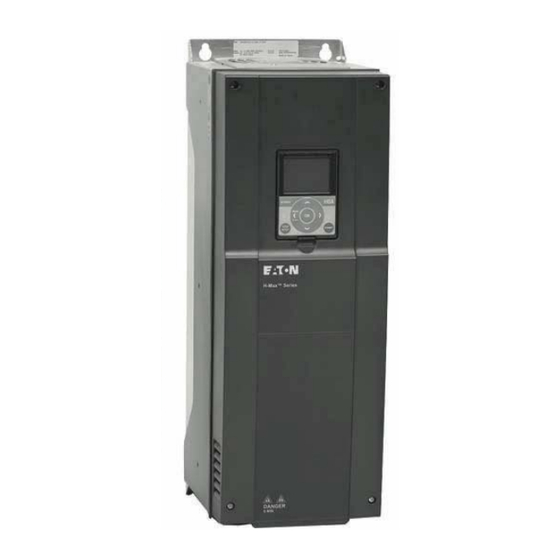
Eaton H-Max Series Installation Manual
Adjustable frequency drive
Hide thumbs
Also See for H-Max Series:
- Installation manual (134 pages) ,
- Manual (46 pages) ,
- Quick start manual (28 pages)
Summary of Contents for Eaton H-Max Series
- Page 1 H-Max™ Series Adjustable Frequency Drive Installation Manual for models using the old style control board...
- Page 3 The information, recommendations, descriptions, and safety notations in this document are based on Eaton Electrical Inc. and/or Eaton Corporation’s (“Eaton”) experience and judgment, and may not cover all contingencies. If further information is required, an Eaton sales office should be consulted.
- Page 4 H-Max Series Adjustable Frequency Drive Support Services The goal of Eaton is to ensure your greatest possible satisfaction with the operation of our products. We are dedicated to providing fast, friendly, and accurate assistance. That is why we offer you so many ways to get the support you need. Whether it’s by phone, fax, or e-mail, you can access Eaton’s support information 24 hours a day, seven days a week.
-
Page 5: Table Of Contents
H-Max Series Adjustable Frequency Drive Table of Contents SAFETY Before Commencing the Installation ....... . . - Page 6 Wiring the AFD ............H-Max Series Adjustable Frequency Drive ........
- Page 7 H-Max Series Open Drives ........
-
Page 8: Before Commencing The Installation
H-Max Series Adjustable Frequency Drive Safety Warning! Dangerous Electrical Voltage! Before Commencing the Installation Disconnect the power supply of the device Measures should be taken to ensure the proper restart of ● ● programs interrupted after a voltage dip or failure. This Ensure that devices cannot be accidentally restarted ●... -
Page 9: Definitions And Symbols
H-Max Series Adjustable Frequency Drive Safety Definitions and Symbols Warnings and Cautions WARNING CAUTION This symbol indicates high voltage. It calls your When selecting the cable cross-section, take the voltage attention to items or operations that could be dangerous drop under load conditions into account. - Page 10 H-Max Series Adjustable Frequency Drive WARNING CAUTION The frequency inverter outputs (U, V, W) must not be Debounced inputs may not be used in the safety circuit connected to the input voltage (destruction of the diagram. device, risk of fire).
-
Page 11: Engineering
Engineering Engineering Introduction This chapter describes the most important features in the energy circuit of a drive system (PDS = Power Drive System) that you should take into consideration in your project planning. Drive System (PDS) Item Number Description Network configuration, input voltage, input frequency, interaction with p.f. -
Page 12: Electrical Power Network
Electrical Power Network Input Connection and Configuration Input Voltage and Frequency The H-Max series frequency inverters can be connected and The standardized input voltages (IEC 60038, VDE017-1) for operated with all control-point grounded AC power networks energy suppliers (EVU) guarantee the following conditions at (see IEC 60364 for more information). - Page 13 Compensation on the power supply side is not required for the direct connection of greater power ratings, deviations H-Max series frequency inverters. From the AC power from the ideal voltage form and asymmetrical voltages can supply network, they take on very little reactive power of the be caused in three-phase AC power networks.
-
Page 14: Safety And Switching
Engineering Safety and Switching Fuses and Cable Cross-Sections Residual-Current Device (RCD) The fuses and wire cross-sections allocated for power-side RCD (Residual Current Device): Residual current device, connections depend on the rated input current I LN of the residual current circuit breaker (FI circuit breaker). frequency inverter (without input reactor). -
Page 15: Emc Measures
Engineering The leakage current to ground is greater than 3.5 mA with a EMC Measures frequency inverter. Based on the requirements of EN 50178, Electrical components in a system (machine) have a an increased ground (PE) has to be connected. The cable reciprocal effect on each other. -
Page 16: Motor And Application
Engineering Motor and Application Motor Selection Parallel Connection of Several Motors to One Frequency Inverter General recommendations for motor selection: Use three-phase powered asynchronous motors with ● short-circuit rotors and surface cooling, also called asynchronous motors or standard motors for the frequency-controlled drive system (PDS). - Page 17 Engineering Motor and Circuit Type The motor’s stator winding can be connected in a star or Because of the higher thermal loading, using only the next delta configuration, in accordance with the rated operational higher motor output according to the list (1.1 kW) is recommended.
- Page 18 Engineering Bypass Operation If you want to have the option of operating the motor with CAUTION the frequency inverter or directly from the input supply, the input branches must be interlocked mechanically. Debounced inputs may not be used in the safety circuit diagram.
-
Page 19: System Overview
System Overview System Overview Component Identification H-Max Series Description of the H-Max BYPA SS HO A Back 2 sec. BYP ASS STOP RESE T HO A STAR T Back 2 sec. STO P RES ET STA RT Item Number Description... - Page 20 System Overview Block Diagram, Elements of H-Max Frequency Inverters R– U/T1 V/T2 W/T3 Item Number Description Supply L1, L2/N, L3, PE, input supply voltage U LN = U e at 50/60 Hz: HMX32: 200V class, three-phase input connection (3 AC 230V/240V) HMX34: 400V class, three-phase input connection (3 AC 400V/480V) Internal interference suppression filter, category C2 to IEC/EN 61800-3 EMC-connection of internal interference suppression filter to PE...


Need help?
Do you have a question about the H-Max Series and is the answer not in the manual?
Questions and answers