
Related Manuals for Eaton SR-1600 PLUS


Summary of Contents for Eaton SR-1600 PLUS
- Page 1 SR-1600 PLUS Inverter Operation Handbook Document: IPN 997-00012-97A Issue 1, April 2023 Eaton Corporation Eaton.com DCinfo@eaton.com...
- Page 2 In no event will Eaton be responsible to the purchaser or user in contract, in tort (including negligence), strict liability or otherwise for any special, indirect, incidental or consequential damage or loss whatsoever, including but not limited to...
-
Page 3: About This Guide
Please use this email address to report any problems you find in this guide: DCInfo@eaton.com For Further Information and Technical Assistance For further information and technical assistance see Worldwide Support on page 29. Copyright © 2007-2023 Eaton Corporation. All Rights Reserved. IPN 997-00012-97A Issue 1, April 2023... -
Page 5: Table Of Contents
Block Diagram ......................5 Mechanical Drawings ....................5 2.4.1 SR-1600 PLUS Single Module ................... 5 2.4.2 SR-1600 PLUS Rack (19” 2U) .................... 6 SR-1600 PLUS De-rating Curve .................. 7 Protection Mechanism ....................7 Installation and Maintenance ................8 LED Indicator ① ......................9 Introduction ....................... -
Page 7: Safety Instructions
Install the inverter in a well-ventilated area. Do not block the front air vents, or the rear air exhausts of the unit. Copyright © 2007-2023 Eaton Corporation. All Rights Reserved. IPN 997-00012-97A Issue 1, April 2023... - Page 8 This equipment must be installed in an enclosed cabinet rack and dummy inverter modules must be installed in positions where working modules are not required. Inverter rack/shelves must be mechanically supported and fixed both at the front and the rear. Copyright © 2007-2023 Eaton Corporation. All Rights Reserved. IPN 997-00012-97A Issue 1, April 2023...
-
Page 9: Functional Characteristics Introduction
2 Functional Characteristics Introduction 2.1 System The SR-1600 PLUS is a highly reliable, modular design DC-AC inverter system, designed with advanced power electronics and microprocessor technology offering the following features: Simple setting and scalable system capacity that supports up to 32 pcs (51.2KW) ... -
Page 10: Electrical Specification
Over Voltage / Under Voltage / Reverse Polarity Protection AC Input Over Voltage / Under Voltage / Over Current Output Short Circuit / Overload / Over Temperature Inverter to Utility 0 second Copyright © 2007-2023 Eaton Corporation. All Rights Reserved. IPN 997-00012-97A Issue 1, April 2023... -
Page 11: Block Diagram
PLUS PLUS PLUS Transfer Utility AC to 0 second Performance Inverter Operating Temp. -25°C ~ 40°C; refer to SR-1600 PLUS power de-rating curve Storage Temp. -40℃~70℃ Environment Relative Humidity 95%, non-condensing Vibration Meet BS EN 61373 Safety standards Meets UL 62368-1... -
Page 12: Sr-1600 Plus Rack (19" 2U)
2.4.2 SR-1600 PLUS Rack (19” 2U) Figure 2. SR-1600 PLUS mechanical drawing-rack Copyright © 2007-2023 Eaton Corporation. All Rights Reserved. IPN 997-00012-97A Issue 1, April 2023... -
Page 13: Sr-1600 Plus De-Rating Curve
2.5 SR-1600 PLUS De-rating Curve Figure 3. SR-1600 PLUS de-rating curve: SR-1600-124/224 PLUS Figure 4. SR-1600 PLUS de-rating curve: SR-1600-148/248 PLUS 2.6 Protection Mechanism Over Voltage Under Voltage Type Shutdown Restart Alarm Shutdown Restart Alarm 130±3% 125±3% 125±3% 90±3% 95±3% 95±3%... -
Page 14: Installation And Maintenance
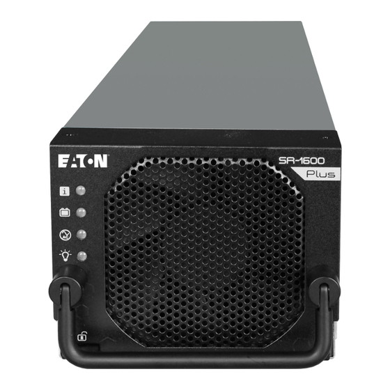
3 Installation and Maintenance 3.1 Introduction Figure 5. SR-1600 PLUS module front panel view Figure 6. SR-1600 PLUS shelf front panel view Table 3. SR-1600 PLUS description Copyright © 2007-2023 Eaton Corporation. All Rights Reserved. IPN 997-00012-97A Issue 1, April 2023... -
Page 15: Led Indicator ①
Figure 7. SR-1600 PLUS shelf rear panel view Table 4. SR-1600 PLUS 3.1.1 LED Indicator ① Description Icon Description Icon AC input power indicator System status LED indicator Load indicator DC battery power indicator Copyright © 2007-2023 Eaton Corporation. All Rights Reserved. - Page 16 Battery under Under voltage frequency voltage Slow Blinking (Default <180V) (50/60Hz) (Default <36V) Abnormal Intermittent Temp. protection Frequency Blinking Intermittent Fan failure Blinking Table 5. LED indicator Copyright © 2007-2023 Eaton Corporation. All Rights Reserved. IPN 997-00012-97A Issue 1, April 2023...
-
Page 17: Green Terminal Introduction ③⑧⑨
Parallel connection: non-terminal shelf (Refer to 3-2-2.) Table 8. SR-1600 PLUS jumper A & B status description *Note: Jumper A pin1 & pin2 must be shorted and Jumper B pin1 & pin2 must be shorted. Dry contact and remote ⑨... - Page 18 Figure 9-1. Application diagram of dry contact pin3~5(Major) Figure 9-2. Application diagram of dry contact pin6~8(Minor) Copyright © 2007-2023 Eaton Corporation. All Rights Reserved. IPN 997-00012-97A Issue 1, April 2023...
- Page 19 Figure 9-3. Application diagram of dry contact pin12~13(Major) Figure 9-4. Application diagram of dry contact pin14~13(Minor) Figure 9-5. Application diagram of dry contact pin1~2 Copyright © 2007-2023 Eaton Corporation. All Rights Reserved. IPN 997-00012-97A Issue 1, April 2023...
- Page 20 Signal voltage: 5V wire size 20~24AWG / 0.5~0.25mm Low: 0V Normal Digital signal input for Pin 13~14 Minor alarm Table 9. SR-1600 PLUS CN3 status description Possible Cause Alarm Description The system over the rated capacity (OLA >15sec) Overload Module Fault Parallel Fault or Module Fault Over Temp.
-
Page 21: Ac Input / Output Terminal ④⑦
AC Input Terminal ④ SR-1600 PLUS provides the AC utility input terminal at the rear side, and the user can connect the AC cable at L / N / PE. The SR-1600 PLUS supports the AC input side internal parallel connection. -
Page 22: Battery Cabling ⑪⑫⑬⑭
Connect the 24V/48V battery [+] / [-] to the SR-1600 PLUS [DC+] / [DC-] There are four battery input sets (DC+, DC-) on the SR-1600 PLUS rear side, and every set is independent. In case the user needs parallel connection, please do the parallel wiring outside the SR-1600 PLUS (please refer to following typical wiring figures). - Page 23 Figure 13. SR-1600 PLUS battery cabling (multi battery I) Figure 14. SR-1600 PLUS battery cabling (multi battery II) Please refer to the suggested battery cable size. Cable diameter / Fuse (slow) / Fuse (slow) / Models AWG / mm per module...
-
Page 24: Chassis Ground ⑮
Figure 15. SR-1600 PLUS installation space requirement Note: Keep minimum 20 cm clear space for air flow at front and rear side of SR-1600 Plus. Note: The rack chassis must be fixed and supported at both the front and rear. -
Page 25: Parallel Connection
3.2 Parallel Connection 3.2.1 Multi-shelves Installation There are two parallel connection methods for the SR-1600 PLUS system capacity expansion: 3.2.2 Parallel Connection with Jumper Setting Please make sure below DIP Switch (SW1 on RS485 board) setting is done following each parallel connection Copyright ©... - Page 26 DIP Switch RACK 1 Figure 17-1. Parallel Connection via jumper setting DIP Switch RACK 1 RACK 2 Figure 17-2. Parallel Connection via jumper setting Copyright © 2007-2023 Eaton Corporation. All Rights Reserved. IPN 997-00012-97A Issue 1, April 2023...
- Page 27 Unit 2 Unit 3 JUMP Connected Not connected Connected ※ Take 3 units for example, only the first and the last unit need to connect jumper. Copyright © 2007-2023 Eaton Corporation. All Rights Reserved. IPN 997-00012-97A Issue 1, April 2023...
-
Page 28: Maintenance
Step 2: Remove the SR-1600 PLUS out of the shelf Figure 20. Remove the inverter module: step 2 Insert the inverter module Step 1: Insert the SR-1600 PLUS Plus into the shelf slot Figure 21. Insert the inverter module: step 1 Copyright © 2007-2023 Eaton Corporation. All Rights Reserved. -
Page 29: Fan Module Replacement
Warning! Please utilise a technically competant person to replace fan the module. Step 1: Please follow the 3-3-1-1. to remove the SR-1600 PLUS module out of shelf. Step 2: Use a screwdriver to remove the 4 screws on the fan module (top side 2 pcs, rear side 2 pcs), and user can then remove the fan module. - Page 30 1. Please make sure the fan power cable is connected well. 2. Suggest cleaning the dust of the fan guards (every 3 months), to keep the fans operating longer. Copyright © 2007-2023 Eaton Corporation. All Rights Reserved. IPN 997-00012-97A Issue 1, April 2023...
-
Page 31: Trouble Shooting
Check the AC source voltage 1. Check the connection and make LED red solid on Short / Overload sure the cable is not short 2. Reduce the load Copyright © 2007-2023 Eaton Corporation. All Rights Reserved. IPN 997-00012-97A Issue 1, April 2023... -
Page 32: Warranty
Eaton or local distributor. Your local Eaton sales office can confirm the warranty status, duration and conditions. This warranty will be considered void if the unit has been misused, altered, or accidentally damaged. Eaton is not liable for anything that occurs as a result of the user’s fault. -
Page 33: Equipment Incident Report
Please enter as much information as you can. Send the completed form, together with the item for repair to your nearest authorized service agent. NOTE: Only one fault to be recorded per form. For further information contact your local Eaton dc product supplier or Eaton (see contact details on page 39). Date: ________________... - Page 34 ______________________________________________________________________________________ ______________________________________________________________________________________ ______________________________________________________________________________________ ______________________________________________________________________________________ ______________________________________________________________________________________ ______________________________________________________________________________________ ______________________________________________________________________________________ ______________________________________________________________________________________ ______________________________________________________________________________________ ______________________________________________________________________________________ ______________________________________________________________________________________ ______________________________________________________________________________________ Internal use only. Reference No: __________ RMA: __________ NCR: __________ Signature: _________________ Date: _______________ Copyright © 2007-2023 Eaton Corporation. All Rights Reserved. IPN 997-00012-97A Issue 1, April 2023...
-
Page 35: Contacts
Contacts 7 Contacts For product information and a complete listing of worldwide sales offices, visit Eaton's website at: Eaton.com or email: DCinfo@eaton.com Copyright © 2007-2023 Eaton Corporation. All Rights Reserved. IPN 997-00012-97A Issue 1, April 2023...
Need help?
Do you have a question about the SR-1600 PLUS and is the answer not in the manual?
Questions and answers