Table of Contents
Advertisement
Advertisement
Table of Contents
Troubleshooting

Related Manuals for Covidien Force FX-C


Summary of Contents for Covidien Force FX-C
- Page 1 User’s Guide Force FX Electrosurgical Generator C...
- Page 3 User’s Guide Force FX Electrosurgical Generator C 1012638...
-
Page 4: Conventions Used In This Guide
Preface This manual and the equipment it describes are for use only by qualified medical professionals trained in the particular technique and surgical procedure to be performed. It is intended as a guide for servicing the Force FX Electrosurgical Generator C only. Additional information is available in the Force FX Electrosurgical Generator C Service Manual. -
Page 5: Limited Warranty
This limited warranty does not apply to any product, or part thereof, which has been repaired or altered in a way so as, in Covidien’s judgment, to affect its stability or reliability, or which has been subjected to misuse, neglect, or accident. - Page 6 County of Boulder, State of Colorado, USA. Covidien reserves the right to make changes in covered products built or sold by it at any time without incurring any obligation to make the same or similar changes to equipment previously built or sold by it.
-
Page 7: Table Of Contents
Table of Contents Preface ..........ii Conventions Used in this Guide . - Page 8 Before Surgery ........3-5 Active Accessories .
- Page 9 Step 3 – Ship the Generator ......8-4 Covidien Service Centers ....... 8-4 Chapter 9.
- Page 10 Expansion Port ........9-6 Low Frequency (50–60 Hz) Leakage Current ... . 9-6 High Frequency (RF) Leakage Current .
-
Page 11: Chapter 1. Introduction
Chapter 1 Introduction This chapter includes information about: • Instant Response technology • Bipolar modes • Monopolar cut and coag modes • Simultaneous coag • REM Contact Quality Monitoring System • Ultrasonic electrosurgery. Caution Read all warnings, cautions, and instructions provided with this generator before using. Read the instructions, warnings, and cautions provided with electrosurgical accessories before using. -
Page 12: Overview
Force Argon system compatibility. Covidien electrosurgical generators, patient return electrodes, and active accessories are designed to work as a system. Covidien offers a selection of patient return electrodes and electrosurgical instruments that are fully compatible with this generator. When considering other manufacturer’s patient return electrodes and/or active accessories,... -
Page 13: Monopolar Cut And Coag Modes
Monopolar Cut and Coag Modes Three bipolar modes are available: precise, standard, and macrobipolar. • Precise (low) may be used when a high degree of precision and fine control over the amount of desiccation are essential. Voltage is kept low to prevent sparking. The power remains constant over a specific range of tissue resistance, allowing a consistent tissue effect. -
Page 14: Simultaneous Coag
The Force FX-C generator uses the REM Contact Quality Monitoring System to monitor the quality of electrical contact between the patient return electrode and the patient. The system is designed to minimize the risk of burns at the return electrode site due to a reduction in patient contact area during monopolar electrosurgery. -
Page 15: Electrodes Without The Rem Safety Feature
Ultrasonic Electrosurgery The Force FX-C generator works in conjunction with the CUSA System 200 and CUSA EXcel for procedures where combined ultrasonic dissection and electrosurgical cutting and coagulation is desired, either simultaneously or independently. In addition to... -
Page 17: Chapter 2. Controls, Indicators And Receptacles
Chapter 2 Controls, Indicators and Receptacles This chapter describes the front and rear panels, including all controls, indicators, receptacles, the fuse drawer, and ports. Force FX Electrosurgical Generator C User’s Guide... -
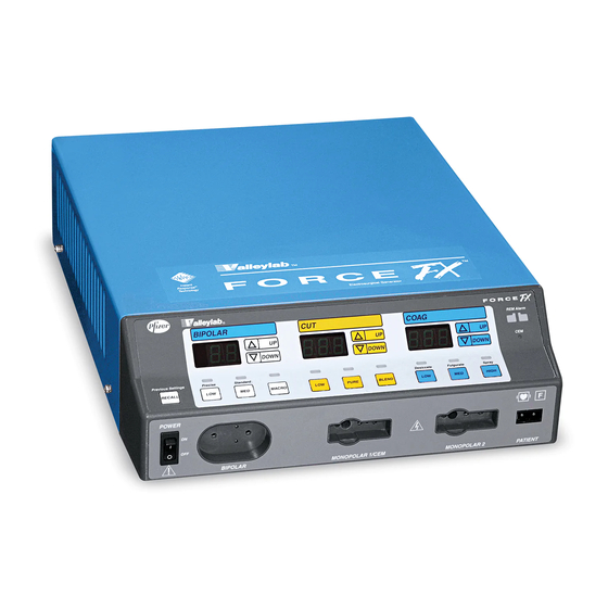
Page 18: Front Panel
Front Panel Front Panel Recall button Pressing this button sets the generator to the most recently used mode and REM alarm power settings. indicator CEM indicator Coag controls Cut controls Bipolar controls Bipolar Instrument receptacle Monopolar 2 Instrument receptacle Monopolar 1/CEM Instrument receptacle Power Switch This switch supplies... -
Page 19: Bipolar Controls
Bipolar Controls Bipolar Controls Bipolar indicator When you activate bipolar, this indicator illuminates blue and an activation tone sounds. Bipolar display Shows the power setting, in watts, for the selected mode. Power buttons Δ Press to increase the power. ∇ Press to decrease the power. -
Page 20: Bipolar Instrument Receptacle
Bipolar Instrument Receptacle Bipolar Instrument Receptacle Caution Accessories must be connected to the proper receptacle type. In particular, bipolar accessories must be connected to the Bipolar receptacle only. Improper connection may result in inadvertent generator activation or a REM Contact Quality Monitor alarm You can connect either a footswitching or handswitching bipolar instrument to the Bipolar receptacle. -
Page 21: Monopolar Cut Controls
Bipolar Instrument Receptacle Monopolar Cut Controls Cut indicator Cut display When you activate cut, this Shows the power indicator illuminates yellow and setting, in watts, for the an activation tone sounds. selected mode. Mode indicators Illuminate green when Power buttons you press the Δ... -
Page 22: Monopolar Coag Controls
Monopolar Coag Controls Monopolar Coag Controls Coag indicator Coag display When you activate coag, this Shows the power setting, indicator illuminates blue and in watts, for the selected an activation tone sounds. mode. Mode indicators Illuminates green when you press the Power buttons corresponding mode Δ... -
Page 23: Monopolar Instrument Receptacles
You can connect a footswitching or handswitching monopolar instrument to the monopolar receptacles. Some footswitching instruments may require a single-pin adapter (E0502 Series or E0017), available from Covidien. Connect one monopolar instrument to the Monopolar 1/CEM Instrument receptacle: • A single-pin footswitching instrument or a three-pin handswitching instrument •... -
Page 24: Rem Alarm Indicator
REM Alarm Indicator REM Alarm Indicator This indicator illuminates red until you properly apply a REM Polyhesive patient return electrode to the patient and connect it to the generator. Then the indicator illuminates green. (When you connect an electrode without the REM safety feature, the indicator does not illuminate.) If the REM system senses an alarm condition, the indicator flashes red until you correct the alarm condition—then the indicator illuminates green. -
Page 25: Rear Panel
Rear Panel Rear Panel Line fuse locator Volume control Power entry module Bipolar Footswitch receptacle Option panel Monopolar Footswitch Equipotential grounding lug receptacles Use to connect the generator to earth ground. Force FX Electrosurgical Generator C User’s Guide... -
Page 26: Footswitch Receptacles
Footswitch Receptacles Footswitch Receptacles The rear panel contains three footswitch receptacles: two for monopolar and one for bipolar. Monopolar Footswitch Receptacles You must connect a monopolar footswitch if you connect a monopolar footswitching instrument to the generator. Use only a Valleylab monopolar footswitch with the Force FX-C generator. -
Page 27: Power Entry Module
Power Entry Module Power Entry Module The power entry module consists of a power cord receptacle and a fuse drawer. Fuse drawer The fuse drawer contains two fuses. The Force FX Electrosurgical Generator C Service Manual contains instructions for changing the fuses. -
Page 28: Option Panel
After obtaining information or removing a peripheral device, reinstall the original cover plate. Notice Do not operate the Force FX-C generator without an appropriate cover plate in place. To review the technical specifications for each port, refer to Output Characteristics on page 9-11. -
Page 29: Chapter 3. Patient And Operating Room Safety
Chapter 3 Patient and Operating Room Safety The safe and effective use of electrosurgery depends to a large degree upon factors solely under the control of the operator. There is no substitute for a properly trained and vigilant surgical team. It is important that the operating instructions supplied with this or any electrosurgical equipment be read, understood, and followed. -
Page 30: General
Electrosurgery may cause multiple activations of ICDs. Covidien recommends against the use of laparoscopic surgery on pregnant patients. Do not use electrosurgical equipment unless properly trained to use it in the specific procedure being undertaken. Use by physicians without such training has resulted in serious, unintended patient injury, including bowel perforation and unintended, irreversible tissue necrosis. -
Page 31: Fire/Explosion
General Fire/Explosion Danger Explosion Hazard—Do not use electrosurgery in the presence of flammable anesthetics. Warning Fire/Explosion Hazard—The following substances will contribute to increased fire and explosion hazards in the operating room: • Flammable substances (such as alcohol-based skin prepping agents and tinctures) •... -
Page 32: Inadvertent Radio Frequency Burns
• In addition, place patient return electrodes according to the manufacturer’s instructions. Potential for alternate site burns increases if the return electrode is compromised. Covidien recommends the use of REM Polyhesive patient return electrodes and Covidien generators with the REM system. -
Page 33: Servicing
Before Surgery Servicing Warning Electric Shock Hazard—Do not remove the cover. Contact authorized personnel for service. Notice Refer to this generator’s service manual for maintenance recommendations and function and output power verification procedures. Before Surgery Active Accessories Warning Electric Shock Hazard—Do not connect wet accessories to the generator. Connect accessories to the proper receptacle. -
Page 34: Patient Return Electrodes
If the instrument manufacturer recommends the use of a shunt cord (s-cord) to direct the current back to the generator, you must also use a Covidien E0507B adapter. To avoid a REM alarm, you must use a REM Polyhesive patient return electrode with the E0507B adapter. -
Page 35: During Surgery
The Force FX-C generator cuts effectively at power settings lower than previous models offered by Covidien. If the proper setting is not known, set the generator at a very low setting and cautiously increase the power until the desired effect is achieved. -
Page 36: Forceps
During Surgery Forceps Notice Do not activate the generator until the forceps have made contact with the patient. Product damage may occur. Suction Coagulators Warning To avoid the possibility of a burn to the surgeon, always turn the generator off before bending or reshaping the coagulator suction tube. -
Page 37: Active Accessories
During Surgery Active Accessories Warning Fire Hazard—Do not place active accessories near or in contact with flammable materials (such as gauze or surgical drapes). Electrosurgical accessories that are activated or hot from use can cause a fire. Use a holster to hold electrosurgical accessories safely away from patients, the surgical team, and flammable materials. -
Page 38: Laparoscopic Procedures
During Surgery Laparoscopic Procedures Warning For laparoscopic procedures, be alert to these potential hazards: • Laparoscopic surgery may result in gas embolism due to insufflation of gas in the abdomen. • The electrode tip may remain hot enough to cause burns after the electrosurgical current is deactivated. -
Page 39: After Surgery
After Surgery After Surgery Warning Electric Shock Hazard—Always turn off and unplug the generator before cleaning. Caution Do not reuse or resterilize accessories labeled “disposable” or “single use only.” Notice Do not clean the generator with abrasive cleaning or disinfectant compounds, solvents, or other materials that could scratch the panels or damage the generator. -
Page 41: Chapter 4. Before Surgery
Chapter 4 Before Surgery This chapter contains procedures for: • Preparing the generator for surgery • Preparing for bipolar or macrobipolar surgery • Preparing for monopolar surgery • Preparing for ultrasonic electrosurgery. Caution Read all warnings, cautions, and instructions provided with this generator before using. Read the instructions, warnings, and cautions provided with electrosurgical accessories before using. -
Page 42: Quick Setup Instructions
Quick Setup Instructions Quick Setup Instructions If you are familiar with the Force FX-C generator, you may prefer to follow this abbreviated procedure. If, however, you are not familiar with how the generator should be set up, detailed instructions follow this chapter. -
Page 43: Setting Up The Generator
1. Verify the generator is off by pressing the power switch off ( O ). 2. Place the generator on a stable flat surface, such as a table, platform, or Covidien cart. Carts with conductive wheels are recommended. For details, refer to the procedures for your institution or to local codes. - Page 44 Setting Up the Generator 4. Plug the generator power cord into a grounded receptacle. 5. Turn on the generator by pressing the power switch on ( | ). Verify the following: – All visual indicators and displays on the front panel illuminate. –...
-
Page 45: Preparing For Bipolar Or Macrobipolar Surgery
Preparing for Bipolar or Macrobipolar Surgery Preparing for Bipolar or Macrobipolar Surgery If you plan to use a footswitching bipolar instrument, you must connect a bipolar footswitch. You may also use a footswitch to activate a handswitching instrument. Connections for Bipolar or Macrobipolar Surgery Warning Electric Shock Hazard —... -
Page 46: Setting The Bipolar Output
Preparing for Bipolar or Macrobipolar Surgery Connection for bipolar or macrobipolar surgery using a handswitching instrument Handswitching instrument Setting the Bipolar Output Caution Set power levels to the lowest setting before testing an accessory. 1. (Optional) To display the previous settings, press the Recall button. 2. -
Page 47: Preparing For Monopolar Surgery
• Do not connect wet accessories to the generator. • Ensure that all accessories and adapters are correctly connected and that no metal is exposed. Use only a Valleylab monopolar footswitch with the Force FX-C generator. Use of an incompatible footswitch may cause unexpected output. - Page 48 Preparing for Monopolar Surgery Connection for monopolar surgery using footswitch activation and a footswitching or handswitching instrument – using Monopolar 1 Footswitch receptacle and Monopolar 1/CEM Instrument receptacle MONOPOLAR 1 FOOTSWITCH Footswitching or handswitching instrument Valleylab monopolar footswitch Patient return electrode Connection for monopolar surgery using footswitch activation and a footswitching or handswitching instrument –...
-
Page 49: Applying A Patient Return Electrode To The Patient
Using a patient return electrode without the REM safety feature will not activate the REM Contact Quality Monitoring System. Covidien recommends using REM Polyhesive patient return electrodes to maximize patient safety. Using a patient return electrode without the REM safety feature may result in a patient burn. -
Page 50: Using Two Generators Simultaneously
Preparing for Monopolar Surgery Using Two Generators Simultaneously Caution Do not stack equipment on top of the generator or place the generator on top of electrical equipment (except a Force GSU unit or a Argon Gas Delivery Unit II). These configurations are unstable and/or do not allow for adequate cooling. -
Page 51: Selecting Cut And Coag Modes
Preparing for Monopolar Surgery Selecting Cut and Coag Modes Caution Set power levels to the lowest setting before testing an accessory. 1. (Optional) To display the previous settings, press the Recall button. 2. To select a cut mode, press the Low, Pure, or Blend button. The corresponding indicator illuminates green. - Page 52 Preparing for Monopolar Surgery Connection for simultaneous coag using two handswitching instruments Monopolar instrument or CUSA handpiece with CEM nosecone Patient return electrode Monopolar instrument Connection for simultaneous coag using two footswitching instruments Monopolar instrument or CUSA handpiece with CEM nosecone Valleylab monopolar Patient return electrode...
-
Page 53: Preparing For Ultrasonic Electrosurgery
Assemble and sterilize the CUSA handpiece and the CEM nosecone. Connecting the Patient Return Electrode Covidien recommends using a REM Polyhesive patient return electrode to maximize patient safety. For further information, refer to Applying a Patient Return Electrode to the Patient on page 4-9. - Page 54 Preparing for Ultrasonic Electrosurgery Connection for combined monopolar/ultrasonic surgery If you choose to use a monopolar footswitch, you must use a Valleylab monopolar footswitch and connect it to the Monopolar 1 Footswitch receptacle. CEM indicator illuminates green. Connect to CUSA system CUSA handpiece with CEM...
-
Page 55: Setting The Output Power
Preparing for Ultrasonic Electrosurgery Setting the Output Power Caution Set power levels to the lowest setting before testing an accessory. When you use the CUSA handpiece with CEM nosecone for ultrasonic electrosurgery, only Low cut or Desiccate coag are available when you activate the handpiece. To verify or change the Low cut power setting: Δ... -
Page 57: Chapter 5. During Surgery
Chapter 5 During Surgery This chapter covers the following topics: • Checking accessory connections • Checking the patient return electrode • Changing the mode • Selecting the power setting • Activating the surgical instrument • Adjusting the volume of activation tones •... -
Page 58: Checking Accessory Connections
Checking Accessory Connections Checking Accessory Connections Warning Do not wrap the accessory cords or patient return electrode cords around metal objects. This may induce currents that could lead to shocks, fires, or injury to the patient or surgical team. Caution Examine all accessories and connections to the electrosurgical generator before using. -
Page 59: Selecting The Power Setting
During a surgical procedure, the amount of current delivered during a given time period determines the amount of heating that occurs under the electrode. All Covidien patient return electrodes are designed for use during traditional surgical procedures and duty cycles (on time compared to off time). -
Page 60: Techniques For Keeping Power Settings Low
Selecting the Power Setting Techniques for Keeping Power Settings Low The power setting required to produce the desired surgical effect varies depending on the surgeon’s technique, the selected mode, and the size of the active electrode. Low power settings reduce the amount of current delivered to the patient, minimize the demand on the patient return electrode, and help protect the patient and surgical team from accidental burns and shocks. -
Page 61: Typical Power Settings
The Force FX-C generator cuts effectively at power settings lower than previous models offered by Covidien. If the proper setting is not known, set the generator at a very low setting and cautiously increase the power until the desired effect is achieved. -
Page 62: Activating The Surgical Instrument
Activating the Surgical Instrument Activating the Surgical Instrument Notice Do not activate the generator until the forceps have made contact with the patient. Product damage may occur. To activate a handswitching instrument, use the controls on the instrument or on the appropriate footswitch. -
Page 63: Adjusting The Volume Of Activation Tones
Adjusting the Volume of Activation Tones Adjusting the Volume of Activation Tones Caution Do not turn the activation tone down to an inaudible level. The activation tone alerts the surgical team when an accessory is active. To change the volume of activation tones, turn the Volume knob on the rear panel: •... -
Page 64: Non-Rem Patient Return Electrode Alarm
Responding to Alarms Non-REM Patient Return Electrode Alarm When a non-REM patient return electrode is connected and the generator detects a cord fault condition, the REM Alarm indicator illuminates red. When you correct the alarm condition, the indicator is extinguished. System Alarm When the generator senses a system alarm condition, an alarm tone sounds and the generator is deactivated. -
Page 65: Chapter 6. After Surgery
Chapter 6 After Surgery This chapter instructs you on: • Preparing the generator for reuse • Storing the generator Force FX Electrosurgical Generator C User’s Guide... -
Page 66: Preparing The Generator For Reuse
Preparing the Generator for Reuse Preparing the Generator for Reuse Caution Do not reuse or resterilize accessories labeled “disposable” or “single use only.” Step 1 – Disconnect the Accessories A. Turn off the generator. B. If applicable, remove the patient return electrode from the patient. Disconnect all accessories from the front panel. -
Page 67: Chapter 7. Troubleshooting
Chapter 7 Troubleshooting This chapter includes: • Correcting a REM alarm condition • Correcting malfunctions • Responding to system alarms Force FX Electrosurgical Generator C User’s Guide... -
Page 68: General Troubleshooting Guidelines
General Troubleshooting Guidelines General Troubleshooting Guidelines If the Force FX-C generator malfunctions, check for obvious conditions that may have caused the problem: • Check the generator for visible signs of physical damage. • Make sure the fuse drawer is tightly closed. -
Page 69: Applying Additional Patient Return Electrodes
Correcting a REM Alarm Condition Applying Additional Patient Return Electrodes If you are using a REM Polyhesive patient return electrode, follow this procedure to correct a REM alarm condition: 1. Inspect the return electrode connector. a. Unplug the patient return electrode from the generator. b. - Page 70 If the alarm persists, go to the next step. 5. Unplug the patient return electrode from the generator. Use a Covidien multiple return/S cord adapter (E0507B) to connect two patient return electrodes to the generator. a. Insert the adapter into the Patient Return Electrode receptacle.
-
Page 71: Correcting Malfunctions
Desiccate mode. Abnormal 50–60 Hz leakage Refer to your Biomedical currents. Engineering Department or contact a Covidien Representative for assistance. Generator does not Disconnected power cord or Check power cord respond when turned on. faulty wall outlet. - Page 72 Generator is on, but did not Software malfunction. Turn off, then turn on the complete the self-test. generator. Internal component Use a backup generator. Refer malfunction. to your Biomedical Engineering Department or contact a Covidien Representative for assistance. Force FX Electrosurgical Generator C User’s Guide...
- Page 73 Turn on the generator. Replace the accessory if it continues to malfunction. Incompatible footswitch. Use only a Covidien footswitch with the Force FX-C generator. Footswitch connected to Connect the footswitch to the Monopolar 1 Footswitch Monopolar 2 Footswitch receptacle is being used for receptacle.
- Page 74 Contact your ground. The generator may Biomedical Engineering respond to the resulting Department or a Covidien voltage differences between Representative for assistance. grounded objects. Malfunctioning monitor. Replace the monitor.
- Page 75 Correcting Malfunctions Situation Possible Cause Solution Pacemaker interference. Intermittent connections or Check the active and patient metal-to-metal sparking. return electrode cord connections. It may be necessary to reprogram the pacemaker. Current traveling from active Use bipolar instruments, if to return electrode during possible.
-
Page 76: Responding To System Alarms
Department. 17–18 Internal component Do not attempt to use the generator. Record malfunction. the number and call the Covidien Service Center. Internal component Turn off, then turn on the generator. If the malfunction. alarm number reappears, record the number and call the Covidien Service Center. - Page 77 Turn off, then turn on the generator. If the alarm number reappears, record the number and call the Covidien Service Center. Internal component Do not attempt to use the generator. Record malfunction. the number and call the Covidien Service Center. Microcontroller malfunction. Contact your Biomedical Engineering Department. 100–105 Software malfunction.
- Page 78 Department. Microcontroller malfunction. 170–173 Software malfunction. Turn off, then turn on the generator. If the alarm number reappears, record the number and call the Covidien Service Center. 180–185 Internal diagnostics. Contact your Biomedical Engineering Department. Software malfunction. Turn off, then turn on the generator. If the alarm number reappears, record the number and call the Covidien Service Center.
- Page 79 Cut up arrow, cut down arrow, and/or a cut mode If the alarm number reappears, record the button (Low, Pure, Blend) may number and call the Covidien Service be stuck. Center. Coag up arrow, coag down arrow, and/or a coag mode button (Desiccate, Fulgurate, Spray) may be stuck.
- Page 80 Number Description Recommended Action 210–211 Software malfunction. Turn off, then turn on the generator. If the alarm number reappears, record the number and call the Covidien Service Center. 212–213 Internal diagnostics. Contact your Biomedical Engineering Department. 220–226 Internal diagnostics or microcontroller malfunction.
-
Page 81: Chapter 8. Maintenance And Repair
Chapter 8 Maintenance and Repair Refer to this chapter for information on: • The manufacturer’s responsibility • Routine maintenance • Returning the generator for service • Service centers Force FX Electrosurgical Generator C User’s Guide... -
Page 82: Responsibility Of The Manufacturer
Responsibility of the Manufacturer Responsibility of the Manufacturer Covidien is responsible for the safety, reliability, and performance of the generator only under the following circumstances: • Installation and setup procedures in this manual are followed. • Assembly operation, readjustments, modifications, or repairs are carried out by persons authorized by Covidien. -
Page 83: Returning The Generator For Service
Number. Then, clean the generator and ship it to Covidien for service. Step 1 – Obtain a Return Authorization Number Call the Covidien Customer Service Center for your area to obtain a Return Authorization Number. Have the following information ready when you call: •... -
Page 84: Step 3 - Ship The Generator
C. Ship the generator, prepaid, to the Covidien Service Center. Covidien Service Centers For a complete list of service centers world-wide, please refer to the Covidien web site: http://www.valleylab.com/valleylab/international/service-world.html Force FX Electrosurgical Generator C User’s Guide... -
Page 85: Chapter 9. Technical Specifications
Chapter 9 Technical Specifications All specifications are nominal and subject to change without notice. A specification referred to as “typical” is within ± 20% of a stated value at room temperature (77° F/25° C) and a nominal input power voltage. Force FX Electrosurgical Generator C User’s Guide... -
Page 86: Performance Characteristics
Display Eight digital seven-segment displays: 0.75" (1.9 cm) each Mounting Covidien carts, CUSA EXcel System, CUSA System 200 (using CUSA System 200 optional mounting brackets), a Force GSU unit, an Argon Gas Delivery Unit II, or any stable flat surface... -
Page 87: Transport And Storage
Performance Characteristics Transport and Storage Ambient temperature -40° to 158° F ( -40° to 70° C) range Relative humidity 25% to 85%, noncondensing Atmospheric pressure 500 to 1060 millibars Duration of storage If stored longer than one year, the battery must be replaced and a full checkout, including calibration, must be completed before use. -
Page 88: Audio Volume
Performance Characteristics Audio Volume The audio levels stated below are for activation tones (bipolar, cut, and coag) and alarm tones (REM and system alarms) at a distance of one meter. Alarm tones meet the requirements for IEC 601-2-2. Activation Tone ≥... -
Page 89: Serial Port
Performance Characteristics Acceptable Resistance Range REM resistance measurements are ± 10% during RF activation and ± 5% when RF output is not activated. REM Polyhesive patient return electrode: 5 to 135 ohms or up to a 40% increase in the initial measured contact resistance (whichever is less) Patient return electrode without the REM safety feature (single section electrode): 0 to 20 ohms... -
Page 90: Expansion Port
Performance Characteristics Expansion Port The 15-pin connector supports the following signals: – Pin 2 – isolated transmit (serial data output transmit line) – Pin 3 – isolated receive (serial data input receive line) – Pin 5 – isolated ground (reference for transmit and receive) –... -
Page 91: Input Power
Performance Characteristics Input Power 100–120 Volt 220–240 Volt Maximum VA at nominal line voltage: Maximum VA at nominal line voltage: Idle: 52 VA Idle: 52 VA Bipolar: 450 VA Bipolar: 450 VA Cut: 924 VA Cut: 924 VA Coag: 530 VA Coag: 530 VA Input mains voltage, full regulation Input mains voltage, full regulation... -
Page 92: Power Cord Specification
Performance Characteristics Power Cord Specification This unit was equipped from the factory with either a 110VAC hospital grade NEMA 5-15 power cord or a 220VAC CEE7/7 power cord. Should the AC power cord need to be replaced to match another plug configuration, the replacement plug/cable/receptacle configuration must meet or exceed the following specifications: 100-120 VAC Cable - SJT16/3, IEC color code, maximum length 15’... -
Page 93: Standards And Iec Classifications
Standards and IEC Classifications Standards and IEC Classifications The Force FX-C generator meets all pertinent clauses of the IEC 60601-1 second edition and IEC 60601-2-2 third edition. ATTENTION Consult accompanying documents. The generator output is floating (isolated) with respect to ground. -
Page 94: Type Cf Equipment (Iec 60601-1)/Defibrillator Proof
ANSI/AAMI HF18 and IEC 60601-2-2. Liquid Spillage (IEC 60601-2-2 Clause 44.3) The Force FX-C generator enclosure is constructed so that liquid spillage in normal use des not wet electrical insulation or other components which when wetted are likely to adversely affect the safety of the equipment. -
Page 95: Output Characteristics
Output Characteristics Output Characteristics Maximum Output for Bipolar and Monopolar Modes Power readouts agree with actual power into rated load to within 15% or 5 watts, whichever is greater. Mode Open Circuit Rated Load Power Crest Factor* P–P Voltage (max) (max) (max) Bipolar... -
Page 96: Maximum Output For Ultrasonic Electrosurgery
Output Characteristics Maximum Output for Ultrasonic Electrosurgery Mode Open Circuit Rated Load Power Crest Factor* P–P Voltage (max) (max) (max) Monopolar Cut Ω 1000 V 100 W Monopolar Coag Ω Desiccate 3500 V 70 W * An indication of a waveform’s ability to coagulate bleeders without a cutting effect Available Power Settings in Watts Bipolar and Macrobipolar 9-12... - Page 97 Output Characteristics Monopolar Cut: Low and Pure Monopolar Cut: Blend Force FX Electrosurgical Generator C User’s Guide 9-13...
- Page 98 Output Characteristics Monopolar Coag CEM Cut 9-14 Force FX Electrosurgical Generator C User’s Guide...
-
Page 99: Output Waveforms
Output Characteristics CEM Coag Output Waveforms Instant Response technology, an automatic adjustment, controls all bipolar modes and all cut modes. It does not control the coag modes because of their fulguration capabilities. As tissue resistance increases from zero, the generator outputs constant current followed by constant power followed by constant voltage. - Page 100 Output Characteristics Monopolar Coag Desiccate 240 kHz sinusoid repeated at 39 kHz; 8% duty cycle Fulgurate 470 kHz damped sinusoidal bursts with a repetition frequency of 30 kHz into 500 ohms LCF Fulgurate 470 kHz damped sinusoidal bursts with a repetition frequency of 57 kHz into 500 ohms Spray 470 kHz damped sinusoidal bursts with a randomized...
-
Page 101: Output Power Vs. Resistance Graphs
Output Power vs. Resistance Graphs Output Power vs. Resistance Graphs The graphs that follow depict the changes for each mode at specific power settings. Note: These curves represent the lower and upper limits of output power with tolerance included. The normal output power will be halfway between these two curves. Bipolar Graphs The insulating surface described in IEC 60601-2-2 was used to obtain the bipolar output measurements. - Page 102 Output Power vs. Resistance Graphs Output power vs. impedance for Precise bipolar 70W mode Load Resistance (ohms) Open circuit peak voltage vs. output power for Precise bipolar mode Output Power (watts) 9-18 Force FX Electrosurgical Generator C User’s Guide...
- Page 103 Output Power vs. Resistance Graphs Output power vs. generator settings Precise bipolar mode Generator Setting Standard Bipolar Mode Output power vs. impedance for Standard bipolar 35W mode Load Resistance (ohms) Force FX Electrosurgical Generator C User’s Guide 9-19...
- Page 104 Output Power vs. Resistance Graphs Output power vs. impedance for Standard bipolar 70W mode Load Resistance (ohms) Note: In the Bipolar Standard mode only, the power curve will reflect both High and Low output values between the impedance range of 475-600 ohms. This is based on the sensed impedance value the generator calculates, and the tolerances of the sensing circuits.
- Page 105 Output Power vs. Resistance Graphs Open circuit peak voltage vs. output power for Standard bipolar mode Output Power (watts) Open circuit peak voltage vs. output power for Standard bipolar mode Generator Setting Force FX Electrosurgical Generator C User’s Guide 9-21...
- Page 106 Output Power vs. Resistance Graphs Macrobipolar Mode Output power vs. impedance for Macrobipolar 35W mode Load Resistance (ohms) Output power vs. impedance for Macrobipolar 70W mode Load Resistance (ohms) 9-22 Force FX Electrosurgical Generator C User’s Guide...
- Page 107 Output Power vs. Resistance Graphs Open circuit peak voltage vs. output power for Macrobipolar mode Output Power (watts) Output power vs. generator settings Macrobipolar mode Generator Setting Force FX Electrosurgical Generator C User’s Guide 9-23...
-
Page 108: Monopolar Cut Graphs
Output Power vs. Resistance Graphs Monopolar Cut Graphs These measurements were taken using short (< 0.5 meter) leads. Low Cut Mode Output power vs. impedance for Low cut 150W mode Load Resistance (ohms) 9-24 Force FX Electrosurgical Generator C User’s Guide... - Page 109 Output Power vs. Resistance Graphs Output power vs. impedance for Low cut 300W mode Load Resistance (ohms) Open circuit peak voltage vs. output power for Low cut mode Output Power (watts) Force FX Electrosurgical Generator C User’s Guide 9-25...
- Page 110 Output Power vs. Resistance Graphs Output power vs. generator settings Low cut mode Generator Setting Pure Cut Mode Output power vs. impedance for Pure cut 150W mode Load Resistance (ohms) 9-26 Force FX Electrosurgical Generator C User’s Guide...
- Page 111 Output Power vs. Resistance Graphs Output power vs. impedance for Pure cut 300W mode Load Resistance (ohms) Open circuit peak voltage vs. output power for Pure cut mode Output Power (watts) Force FX Electrosurgical Generator C User’s Guide 9-27...
- Page 112 Output Power vs. Resistance Graphs Output power vs. generator settings Pure cut mode Generator Setting Blend Cut Mode Output power vs. impedance for Blend cut 100W mode Load Resistance (ohms) 9-28 Force FX Electrosurgical Generator C User’s Guide...
- Page 113 Output Power vs. Resistance Graphs Output power vs. impedance for Blend cut 200W mode Load Resistance (ohms) Open circuit peak voltage vs. output power for Blend cut mode Output Power (watts) Force FX Electrosurgical Generator C User’s Guide 9-29...
- Page 114 Output Power vs. Resistance Graphs Output power vs. generator settings Blend cut mode Generator Setting 9-30 Force FX Electrosurgical Generator C User’s Guide...
-
Page 115: Monopolar Coag Graphs
Output Power vs. Resistance Graphs Monopolar Coag Graphs These measurements were taken using short (< 0.5 meter) leads. Desiccate 1 Coag Mode Output power vs. impedance for Desiccate 1 coag 60W mode Load Resistance (ohms) Force FX Electrosurgical Generator C User’s Guide 9-31... - Page 116 Output Power vs. Resistance Graphs Output power vs. impedance for Desiccate 1 coag 120W mode Load Resistance (ohms) Open circuit peak voltage vs. output power for Desiccate 1 coag mode Output Power (watts) 9-32 Force FX Electrosurgical Generator C User’s Guide...
- Page 117 Output Power vs. Resistance Graphs Output power vs. generator settings Desiccate 1 coag mode Generator Setting Desiccate 2 Coag Mode Output power vs. impedance for Desiccate 2 coag 60W mode Load Resistance (ohms) Force FX Electrosurgical Generator C User’s Guide 9-33...
- Page 118 Output Power vs. Resistance Graphs Output power vs. impedance for Desiccate 2 coag 120W mode Load Resistance (ohms) Open circuit peak voltage vs. output power for Desiccate 2 coag mode Output Power (watts) 9-34 Force FX Electrosurgical Generator C User’s Guide...
- Page 119 Output Power vs. Resistance Graphs Output power vs. generator settings Desiccate 2 coag mode Generator Setting Desiccate 3 Coag Mode Output power vs. impedance for Desiccate 3 coag 60W mode Load Resistance (ohms) Force FX Electrosurgical Generator C User’s Guide 9-35...
- Page 120 Output Power vs. Resistance Graphs Output power vs. impedance for Desiccate 3 coag 120W mode Load Resistance (ohms) Open circuit peak voltage vs. output power for Desiccate 3 coag mode Output Power (watts) 9-36 Force FX Electrosurgical Generator C User’s Guide...
- Page 121 Output Power vs. Resistance Graphs Output power vs. generator settings Desiccate 3 coag mode Generator Setting Fulgurate Coag Mode Output power vs. impedance Fulgurate coag 60W mode Load Resistance (ohms) Force FX Electrosurgical Generator C User’s Guide 9-37...
- Page 122 Output Power vs. Resistance Graphs Output power vs. impedance Fulgurate coag 120W mode Load Resistance (ohms) Output power vs. peak voltage Fulgurate coag mode Output Power (watts) 9-38 Force FX Electrosurgical Generator C User’s Guide...
- Page 123 Output Power vs. Resistance Graphs Output power vs. generator settings Fulgurate coag mode Generator Setting LCF Fulgurate Coag Mode Output power vs. impedance LCF Fulgurate coag 60W mode Load Resistance (ohms) Force FX Electrosurgical Generator C User’s Guide 9-39...
- Page 124 Output Power vs. Resistance Graphs Output power vs. impedance LCF Fulgurate coag 120W mode Load Resistance (ohms) Output power vs. peak voltage LCF Fulgurate mode Output Power (watts) 9-40 Force FX Electrosurgical Generator C User’s Guide...
- Page 125 Output Power vs. Resistance Graphs Output power vs. generator settings LCF Fulgurate mode Generator Setting Spray Coag Mode Output power vs. impedance Spray coag 60W mode Load Resistance (ohms) Force FX Electrosurgical Generator C User’s Guide 9-41...
- Page 126 Output Power vs. Resistance Graphs Output power vs. impedance Spray coag 120W mode Load Resistance (ohms) Output power vs. peak voltage Spray coag mode Output Power (watts) 9-42 Force FX Electrosurgical Generator C User’s Guide...
- Page 127 Output Power vs. Resistance Graphs Output power vs. generator settings Spray coag mode Generator Setting Force FX Electrosurgical Generator C User’s Guide 9-43...
- Page 130 Part No. 1012638 COVIDIEN, COVIDIEN with logo and Covidien logo are U.S. and internationally registered trademarks of Covidien AG. CUSA, CUSA EXcel and CEM are trademarks of Integra LifeSciences Corporation or its subsidiary. Other brands are trademarks of a Covidien company.
Need help?
Do you have a question about the Force FX-C and is the answer not in the manual?
Questions and answers