Sign In
Upload
Manuals
Brands
Covidien Manuals
Medical Equipment
Newport HT70 plus
Covidien Newport HT70 plus Manuals
Manuals and User Guides for Covidien Newport HT70 plus. We have
1
Covidien Newport HT70 plus manual available for free PDF download: Operator's Manual
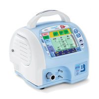
Covidien Newport HT70 plus Operator's Manual (148 pages)
Ventilator with Accessories
Brand:
Covidien
| Category:
Medical Equipment
| Size: 8.68 MB
Table of Contents
Table of Contents
3
1.2 Brief Device Description
13
1.1 Overview
13
Brief Device Description
13
Overview
13
Sophisticated Clinical Capabilities
13
Exceptional Mobility
14
Travel Certified
15
Intended Use
15
Ventilator Configurations
15
1.5 Warnings, Cautions, and Notes
16
1.4 Ventilator Configurations
16
Warnings, Cautions, and Notes
16
1.3 Intended Use
16
General Warnings
16
Table 1-1. HT70 Ventilator Configurations
16
General Cautions
20
General Notes
20
Revision History
20
Warranty Information
21
Contact Information
21
1.8 Contact Information
25
1.7 Warranty Information
25
Overview of Controls, Screens, and Connectors
25
Front Panel Overview
25
Internal Dual Battery System Overview
25
Touch Screen Overview (Hospital Domain)
25
Figure 2-2. Newport HT70 Ventilator Rear Panel
27
Rear Panel Overview
27
Figure 2-3. Newport HT70 Ventilator (Right Side)
28
Right Side Overview
28
Figure 2-4. Newport HT70 Ventilator (Left Side)
29
Left Side Overview
29
Bottom Panel Label
30
Figure 2-5. Newport HT70 Ventilator Bottom Panel Labeling
30
2.7 Bottom Panel Label
31
2.6 Left Side Overview
31
Setup and Pre-Use Preparations
31
Unpacking the Ventilator
31
Table 3-1. Newport HT70PM Ventilator Parts
31
Table 3-2. Optional Accessories
31
Assembling the Ventilator
32
Connecting to AC Power
32
Figure 3-1. Newport HT70 Ventilator and Power Supply
33
Figure 3-2. Pinch-Release Power Plug
33
3.4 Using the Power Switch
34
3.3 Connecting to AC Power
34
3.2 Assembling the Ventilator
34
Using the Power Switch
34
Figure 3-3. Power Switch
34
Turning on the Power
34
Turning off the Power
35
Figure 3-4. Startup Screen
35
Figure 3-5. Shutdown Screen
35
3.6 Attaching a Patient Circuit
36
Attaching a Patient Circuit
36
Making Parameter Changes
36
3.5 Making Parameter Changes
36
With a Third-Party Humidifier
36
Figure 3-6. Patient Circuit Components (Third-Party Humidifier)
37
Figure 3-7. Patient Circuit Connection to Humidifier
38
Figure 3-8. Patient Circuit Connection to Patient Wye (Setup with Humidifier)
39
Figure 3-9. Patient Circuit with Humidifier (Completed Setup)
40
Figure 3-10. Patient Circuit Components (HME)
41
With an HME (Artificial Nose)
41
Figure 3-11. Patient Circuit Connection to Exhalation Valve (Setup with HME)
42
Using the On-Airway Flow Sensor
43
Figure 3-12. Patient Circuit with HME (Completed Setup)
43
Connecting Optional Accessories
44
3.7 Connecting Optional Accessories
44
Air/Oxygen Entrainment Mixer
44
Figure 3-14. Low Flow Oxygen Reservoir
45
Low Flow Oxygen Reservoir
45
Table 3-3. Pneumatic Requirements
45
Figure 3-15. Oxygen Supply Flow Versus Desired Percent of Oxygen (for Use with PEEP)
46
Figure 3-16. Oxygen Supply Flow Versus Desired Percent of Oxygen (for Use Without PEEP)
46
DC Auto Lighter Power Adapter
47
Table 3-4. Pneumatic Requirements
47
Aequitron Remote Alarm Cable
48
Navigating the Screens
49
Primary Screen Navigation
49
Primary Screen Buttons and Displays
50
Figure 4-1. Primary Screen Buttons and Displays
50
Ventilator Settings Adjustment
51
Startup Screen Navigation (Standby Condition Only)
52
Figure 4-2. Startup Screen (Standby Condition)
52
Touch Screen (Graphical User Interface) Layout
49
Circuit Check Button
53
Activate Preset Button
54
Figure 4-4. Activate Presets
54
Start Ventilation Button
55
Alarms Screen Navigation
55
Alarm Loudness Level
56
Figure 4-5. Alarms Screen
56
Settable Alarms
56
Alarm Quickset
57
Main Screen Navigation
57
Figure 4-6. Main Screen
57
More Screen Navigation
59
Figure 4-7. more Screen Buttons
59
More Screen Details
60
Events Screen
60
Figure 4-8. Events Screen
60
Figure 4-9. Trends Screen
61
Trends Screen Navigation
61
Figure 4-10. Waves Screen
62
Waves Screen
62
Figure 4-11. Oxygen Cylinder Data Screen
63
Oxygen Cylinder Data Screen
63
Calibrate O 2 Mon Screen
64
Utility Screen
64
Figure 4-12. Calibrate O2 Mon Screen
64
Utility Screen Details
66
Figure 4-14. Time/Altitude Screen
66
Time/Altitude Screen
66
Custom Settings Screen
67
Figure 4-15. Custom Settings Screen
67
Figure 4-16. Custom Presets
68
Figure 4-17. BUV Settings Screen
68
Domain Navigation
69
Hospital Domain
69
Basic Domain
70
Figure 4-18. Hospital Domain Screen
70
Figure 4-19. Transport Domain Screen
70
Figure 4-20. Basic Domain Screen (Time Display)
71
Figure 4-21. Basic Domain Screen (Settings Display)
71
Operating the Ventilator
73
Transport Domain
70
Equipment Needed
73
Pre-Test Inspection
73
Quick Check Procedure
73
Quick Check Procedure
74
Table 5-1. Standard Test Settings
74
Patient Set-Up Procedure
77
Table 5-2. Troubleshooting
79
Troubleshooting Guide
79
Setting Alarms
89
Setup
74
Standard Test Settings
74
6.1 Setting Alarms
90
6 Ventilator Alarms
90
Alarm Quickset
90
Alarm Indicators
90
6.2 Alarm Indicators
91
Audio Pause LED
91
User-Adjustable Alarms
91
Table 6-1. User-Adjustable Alarms
91
Audio Paused/Reset Button
91
6.3 User-Adjustable Alarms
92
High Pressure Alarm
92
Low Expiratory Minute Volume Alarm
92
Low Inspiratory Minute Volume Alarm
92
Low Pressure Alarm
92
High Expiratory Minute Volume Alarm
93
High Inspiratory Minute Volume Alarm
93
High O 2 Alarm
93
High Respiratory Rate Alarm
93
High Tidal Volume Alarm
93
Low O 2 Alarm
93
Apnea Alarm
94
Backup Ventilation
94
6.5 Automatic Alarms
95
Automatic Alarms
95
6.4 Backup Ventilation
95
High Baseline Pressure Alarm
95
Low Baseline Pressure Alarm
95
Check Circuit or Prox Line Alarm
96
Flow Sensor Disconnect/Failure Alarms
96
No External Power Alarm
96
Occlusion Alarm
96
Pressure Control Setting Not Reached Alarm
96
Sustained Occlusion Alarm
96
Device Alert Alarm-System Error
97
Internal Temperature Alarm
97
Motor Fault Alarm
97
O 2 Cylinder Low/Empty Alarms
97
Battery Alarms
98
Shut down Alert Alarm
97
6.6 Battery Alarms
98
Backup Battery Low Alarm
98
Backup Battery Shutdown Imminent Alarm
98
Integrated Power Pac Failure Alarm
98
Power Pac Battery Pack Low Alarm
98
Running on Backup Battery Alarm
98
Switching to Backup Battery Alarm
98
Backup Battery Failure Alarm
99
Backup Battery Low Charge Alarm
99
Backup Battery Temperature Alarm
99
Battery Operation
101
Power Pac Battery Pack Temperature Alarm
99
Internal Dual Battery System
101
Power Pac Battery Pack
101
Backup Battery
102
Conditions that Affect Battery Use Time
102
Check Battery Charge Level/Battery Time Estimator
103
Best Use Tips
104
Battery System Maintenance
104
Power Pac Battery Pack Removal
105
Battery Alarms Overview
105
Power Accessories
106
AC Power Supply (PWR3204P)
106
Country-Specific Power Cord
106
Power Pac Battery Pack (BAT3271A)
106
DC Auto Lighter Power Adapter (ADP3203P)
107
Cleaning and Maintenance
109
External Battery System (BAT3300A)
107
Cleaning and Disinfecting
109
Definitions
109
Ventilator
110
Accessories
110
Air/Oxygen Entrainment Mixer
110
Reusable Breathing Circuits and Exhalation Valves
111
Air Intake Filter
112
Proximal Inline Filter
112
Maintenance Guidelines
113
Low Flow Oxygen Reservoir
110
Routine Maintenance
113
000-Hour Maintenance (or Every 4 Years)
114
General Warnings
115
Factory Maintenance or Repair
115
Repacking/Return Information
116
Specifications
117
6-Month Maintenance
114
Front Panel Buttons-Symbols Version
117
Table 9-1. Front Panel Buttons-Symbols Version
117
Miscellaneous Reference Symbols
118
Table 9-2. Miscellaneous Reference Symbols
118
Control Data Selection
119
Table 9-3. Control Data Selection
119
Monitor Data Selections
120
Table 9-4. Monitor Data Selections
120
Front Panel Membrane Buttons and Indicators
121
Table 9-5. Front Panel Membrane Buttons and Indicators
121
Table 9-6. Alarms
121
Table 9-7. User-Adjustable Alarms
122
Table 9-8. Automatic Alarms
122
Alarms
121
Hardware Requirements
123
Table 9-9. Hardware Requirements
123
Environment
124
Table 9-10. Environment
124
Size and Weight
125
Table 9-11. Size and Weight
125
Table 9-12. Factory Default Parameters (Patient Settings)
125
Table 9-13. Default Presets (Control Settings)
125
Factory Default Parameters
125
Miscellaneous Specifications
126
Patient Circuit
126
Ventilator Breathing System (VBS) Resistances
127
Pneumatic Requirements (Optional Equipment)
127
Manufacturer's Declaration
127
Table 9-15. VBS Resistances
127
Table 9-16. Pneumatic Requirements
127
Table 9-17. Electromagnetic Emissions
128
Table 9-18. Electromagnetic Immunity
128
Table 9-19. Electromagnetic Immunity-Conducted and Radiated RF
129
Table 9-20. Recommended Separation Distances
130
Performance
131
Table 9-21. Performance Parameter Specifications and Tolerances
131
10 Explanation of Modes and Controls
133
A/CMV Mode
133
SIMV Mode
133
SPONT Mode
134
Niv
134
10.7 VC
135
10.6 Pc
135
10.5 Ps
135
Backup Ventilation
135
Backup Ventilation in A/CMV and SIMV Modes
136
Backup Ventilation in Spont Mode
136
Cancellation of Backup Ventilation
136
Quick Check Procedure Check-Off
140
A Quick Check Procedure Check-Off
142
Foldout Drawings
142
Advertisement
Advertisement
Related Products
Covidien Newport HT70
Covidien HawkOne H1-LS-INT
Covidien HawkOne H1-LX-INT
Covidien HawkOne LS
Covidien HawkOne LX
Covidien Newport e360
Covidien DAR
Covidien Endo Stitch
Covidien Force FX
Covidien Force FX-C
Covidien Categories
Medical Equipment
Accessories
Thermometer
Water Pump
Measuring Instruments
More Covidien Manuals
Login
Sign In
OR
Sign in with Facebook
Sign in with Google
Upload manual
Upload from disk
Upload from URL