Norac UC4+ Installation Manual
Spray height controller.
rogator 1254, 1054, 854 (97+)
Hide thumbs
Also See for UC4+:
- Operator's manual (60 pages) ,
- Installation manual (50 pages) ,
- Manual (31 pages)

Related Manuals for Norac UC4+


Summary of Contents for Norac UC4+
- Page 1 Spray Height Controller Rogator 1254, 1054, 854 (97+) Installation Manual Improving the competitiveness of Industry and Agriculture through Precision Measurement...
- Page 2 Reorder P/N: UC4+BC+RG4-INST Rev C (Rogator 1254, 1054, 854) NOTICE NORAC Systems International Inc. reserves the right to improve products and their specifications without notice and without the requirement to update products sold previously. Every effort has been made to ensure the accuracy of the information contained...
-
Page 3: Table Of Contents
TABLE OF CONTENTS INTRODUCTION ..........................1 GENERAL SYSTEM DESCRIPTION ....................2 PARTS LISTS ............................3 INSTALLATION PROCEDURE ......................10 ......................10 XISTING SYSTEM CHECK ........................10 PEED ....................... 12 ENSOR NSTALLATION ....................15 ENSOR NSTALLATION ....................... 16 ENSOR NSTALLATION 4.5.1 Boom Roll Sensor Mounting.................... -
Page 4: Introduction
INTRODUCTION Congratulations on your purchase of the NORAC UC4+ Spray Height Controller. This system is manufactured with top quality components and is engineered using the latest technology to provide operating features and reliability unmatched for years to come. When properly used the system can provide protection from sprayer boom damage, improve sprayer efficiency, and ensure chemicals are applied correctly. -
Page 5: General System Description
Any installation procedure requiring boom installation. However, NORAC cannot movement will need to be done first. Once the guarantee all parts fit as intended due to the hydraulics have been disconnected you must variations of the sprayer by the manufacturer. -
Page 6: Parts Lists
HOSE ASSEMBLY 122R2-04 18 IN L 6FJX 6FJX 44865-26 HYDRAULICS FITTING KIT - RG4 446BC+MAN7 OPERATOR MANUAL UC4+ SPRAY HEIGHT CONTROL UC4+BC+RG4-INST MANUAL INSTALLATION UC4+ ROGATOR 1254, 1054, 854 ('97+) 44933D VALVE BLOCK ASSEM UC5-BC 2-STATION CC/LS VARIABLE RATE DT... - Page 7 Table 2 – 44865-26 - Hydraulics Fittings Kit Details Picture Item Part Number Name Quantity 44928 ORIFICE INSERT .047 IN ONE WAY 103312 MALE ADAPTER - 6MB 6MJ 104369 PLUG - 6MBP 103839 TEE ADAPTER - 6FJXR 6MJT 104632 TEE ADAPTER - 8FJXR 8MJT 104634 PLUG - 6FJCN CAP NO 6 FEMALE JIC 104517...
- Page 8 Picture Item Part Number Name Quantity 104628 MALE TO FEMALE ADAPTER - 12FJ 8MJ 104386 MALE TO FEMALE ADAPTER - 8FJ 6MJ 6 M B - 6 M OR X 90 Fitting Name Example: ANGLE SIZE IN ° TYPE: SWIVEL 1/16 B - ORB TH'S...
- Page 9 ATTENTION: Your Rogator sprayer may require different cabling depending on the connectors used near the valve block. Please refer to Table 3 and Table 5 for ordering alternate cabling from NORAC. Table 3 – Alternate Interface Cabling Available from NORAC...
- Page 10 Table 5 – Illustrations of Connector Types Weatherpack Metripack 280 Deutsch DT...
- Page 11 The parts that come with your UC4+ Spray Height Control System are shown below in their general installation configuration. Figure 2 – UC4+ Spray Height Control Components *If your valve connectors or cables appear different than shown, refer to Appendix A for more details.
- Page 12 Figure 3 – Hydraulic Plumbing Schematic...
-
Page 13: Installation Procedure
INSTALLATION PROCEDURE 4.1 E XISTING SYSTEM CHECK You will need a stopwatch or a watch that displays “seconds” for It is necessary to check the existing system’s the next step. functionality before installing the UC4+ Spray Height Control system. 3. Raise the LEFT boom from its extreme LOW position to the very TOP of its 1. - Page 14 Table 7 – Boom Test Record (WITHOUT UC4+ Spray Height Control system) Working RPM: Trial #1 Trial #2 Trial #3 Avg Time Boom [Sec] [Sec] [Sec] [Sec] Left UP Left DOWN Right UP Right Down Main UP Main DOWN Roll CW Roll CCW Table 8 –...
-
Page 15: Wing Sensor Installation
UC4+ Spray Height Control Operator’s Manual (M01) implications. 4. Mount the NORAC UC4+ ultrasonic sensor (E02) into the sensor brackets. Figure 5 – Breakaway Sensor Mounting The sensors should be oriented forward Bracket Assembly (ahead) of the boom (see Figure 6 and Figure 8). - Page 16 5. Sensor cables should run through the General mounting rules for UC4+ mounting bracket tube and then behind ultrasonic wing sensors: the member the bracket is mounted onto. a) In its lowest position, the sensor Cable-tie the connector in place. The mouth must be 9 inches or more cable must not be allowed to hang below from the ground.
- Page 17 3 SENSOR SYSTEM 5 SENSOR SYSTEM Figure 9 – Sensor Serial Number Installation Location...
-
Page 18: Main Lift Sensor Installation
4.4 M 3. Mount the sensor onto the sensor ENSOR NSTALLATION mounting collar (Figure 11). 1. Assemble the main lift sensor bracket (B11) as shown in Figure 10. Sensor Mounting Collar Bracket Tube Bracket Base Sensor Mounting Tab Figure 10 – Main Lift Sensor Bracket 2. -
Page 19: Roll Sensor Installation
4.5 R a) The smaller the distance between A ENSOR NSTALLATION and B in Figure 14, the better the Mount the roll sensors to the included performance will be. roll sensor brackets using the machine screws and nylon lock nuts, as illustrated Distance A can not be more than in Figure 13. -
Page 20: Boom Roll Sensor Mounting
* The boom frame roll sensor does not have a temperature probe Figure 15 – Roll Sensor Mounting with Respect to Sprayer Orientation 4.5.1 Boom Roll Sensor Mounting 4.5.2 Chassis Roll Sensor Mounting The boom roll sensor (E04) must be The chassis roll sensor must be mounted mounted to the rotating part of the boom. -
Page 21: Inverted Roll Sensor Mounting
Figure 16 – Boom and Chassis Roll Sensors Correctly Mounted 4.5.3 Inverted Roll Sensor Mounting If desired, the Roll sensor may be boom. Inverted mounting may be used mounted inverted, so long as the optimize mounting criteria connector exits towards the right-hand explained in Section 4.5. -
Page 22: Temperature Probe
4.5.4 Temperature probe Fasten the temperature probe (E03) to the UC4+ valve block using the included 3/8x1/2” bolt as illustrated in Figure 18. Figure 18 – UC4+ Valve Block with Temperature Probe Installed... -
Page 23: Hydraulic Installation
Figure 20 – Valve Block Assembly 4.6.1 Valve Assembly 4.6.2 Valve Mounting 1. On a clean surface remove all plastic 1. Mount the NORAC valve (V01) on the plugs from the NORAC hydraulic Valve (V01) (Figure 19). sprayer using the valve mounting bracket (B10). -
Page 24: Hydraulic Plumbing
From this point in the installation the booms will be inoperative until the electronics are fully installed. 1. After the NORAC valves are mounted, the hydraulic hoses and fittings can be plumbed. plumbing hydraulic circuit is shown schematically in Figure 3. - Page 25 9. Tee H4 in to the open port on F05 using port on F04. F14 (Figure 24). 5. Route H7 and H8 to the NORAC valve 10. Route hoses H4 and H5 from the tee(s) block. Connect to the “B” ports. Follow to the NORAC valve block to supply the existing 3/4"...
-
Page 26: Lectrical Nstallation
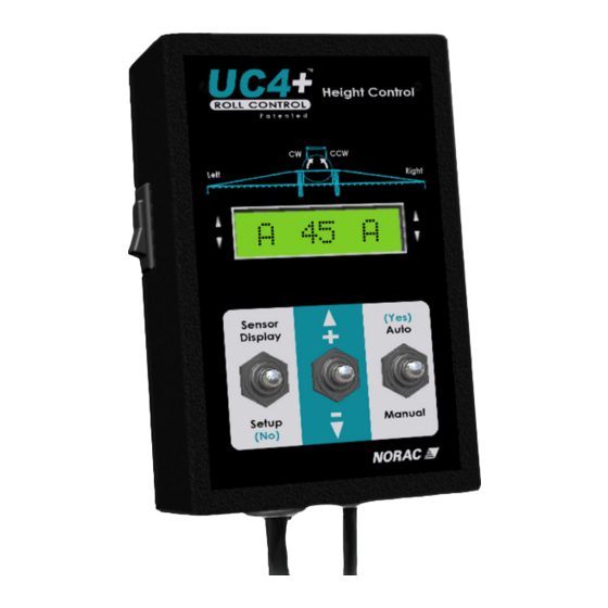
4.7 E LECTRICAL NSTALLATION 1. Install the UC4+ Control Panel (E01) in the cab of the sprayer. Mount the panel where it will be clearly visible and within easy reach of the operator. A good spot to mount the UC4+ control panel is on the right hand side of the cab to the Roll Over Protection Bar. - Page 27 2. Connect the UC4+ power cable (C10) to 5. There is an access hole to the sprayer the UC4+ Control Panel in the sprayer electrical panel on the front right corner. cab. Ensure that both plugs (P16A and Route the free end of C14 to the P4) are connected to the receptacles of electrical panel through this hole.
- Page 28 Figure 29 – Access Panel and Plates Figure 28 – Access Plates Configurations Figure 30 – Cable Configurations: C11, C12, C16 and C03 10. Route C11 to the rear of the sprayer, in Figure 31 illustrates where to tee in the the vicinity of the valve block.
- Page 29 STEP 14. For each connector, the Alternate cabling is available function (e.g. “LEFT UP”) is labeled on from NORAC if the connectors the branch wire of C12. on C12 (and C16) do not match your valve block. Refer to Table 16.
- Page 30 18. Connect the 6-pin Tower on the valve 25. Cable-tie the installed cables every 12 cable (C3) onto the mating connector inches. (S6A) on C11. Figure 33 – Valve Cable Connections Figure 34 – Cable Configurations: C11, 19. As shown in Figure 33, the connectors C02 and C02B are marked RIGHT UP, LEFT UP, RIGHT PORT and LEFT PORT.
-
Page 31: Completing The Installation
Panel using the switch on the side of its chassis. 4. Repeat the Boom Speed Test as described in Section 4.2 Boom Speed Test with the NORAC UC4+ System installed. Record the results for comparison in Table 8. 5. The procedure for the installation of the UC4+ Spray Height Control system is now complete. -
Page 32: Electrical Reference - Cable Drawings
ELECTRICAL REFERENCE – CABLE DRAWINGS 5.1 I C2: 44668 – S ENSOR RANCH ABLE 5.2 I C02B: 44664 – C UC4+ CAN N ABLE... -
Page 33: Item C3: 44656 - Valve Cable (Variable Rate )
5.3 I C3: 44656 – V ALVE ABLE ARIABLE... -
Page 34: Item C10: 44650-39 - Power Cable Generic Self - Proplelled
5.4 I C10: 44650-39 – P OWER ABLE ENERIC PROPLELLED... -
Page 35: Item C11: 44651-03 - Extension Cable Valve Generic
5.5 I C11: 44651-03 – E XTENSION ABLE ALVE ENERIC... -
Page 36: Item C12: 44658-32 - Interface Cable Rogator 854, 1054, 1254
5.6 I C12: 44658-32 – I ROGATOR 854, 1054, 1254 NTERFACE ABLE... -
Page 37: Item C14: 44658-28 - Power Pigtail
5.7 I C14: 44658-28 – P OWER IGTAIL... -
Page 38: Item C15B: 44658-41 - Interface Cable Hand Control Rg4
5.8 I C15B: 44658-41 – I NTERFACE ABLE ONTROL... -
Page 39: Item C16: 44658-33 - Interface Cable Bypass
5.9 I C16: 44658-33 – I NTERFACE ABLE YPASS... -
Page 40: Appendix A - Valve Connector Change
APPENDIX A – VALVE CONNECTOR CHANGE Starting in January 2009, NORAC is changing the connectors on the boom height control valve block. The new style valve block will have 2-pin Deutsch connectors on the coils. The previous models had Hirschman style connectors as shown in Figure 2. - Page 42 Canada NORAC Systems International Inc. CALL TOLL FREE: 1-800-667-3921 (306)664-6711 SHIPPING ADDRESS: 3702 Kinnear Place Saskatoon, SK S7P 0A6 United States Norac, Inc. CALL TOLL FREE: 1-866-306-6722 (763)786-3080 SHIPPING ADDRESS: 1290 Osborne Rd NE, Suite F Fridley, MN 55432-2892...
Need help?
Do you have a question about the UC4+ and is the answer not in the manual?
Questions and answers