Norac UC4+ Operator's Manual
Spray height controller
Hide thumbs
Also See for UC4+:
- Operator's manual (60 pages) ,
- Installation manual (50 pages) ,
- Manual (31 pages)
Table of Contents
Advertisement
Advertisement
Table of Contents

Related Manuals for Norac UC4+


Summary of Contents for Norac UC4+
- Page 1 Spray Height Controller Operator Manual Version 7 Software...
- Page 2 Reorder P/N: 446BC+MAN7 Rev C (UC4+ Operator Manual) NOTICE: NORAC Systems International Inc. reserves the right to improve products and their specifications without notice and without the requirement to update products sold previously. Every effort has been made to ensure the accuracy of the information...
-
Page 3: Table Of Contents
Contents 1 INTRODUCTION ..................... 1 2 SAFETY PRECAUTIONS ................. 2 3 KEY FEATURES ....................3 4 SYSTEM DESCRIPTION .................. 4 4.1 General UC4+ System Layout ..........................4 4.2 Height Sensors ................................5 4.3 Roll Sensors ................................5 4.4 Control Panel ................................5 5 OPERATION ..................... - Page 4 9.6 Minimum Height Mode ............................35 9.7 Changing the Units ..............................35 9.8 Valve and Air Temperature ........................... 35 10 MAINTENANCE ..................... 36 11 TROUBLESHOOTING ................... 37 11.1 General Operation ..............................37 11.2 Sensors ..................................38 11.3 Hydraulics .................................. 40 11.4 Boom Stability ................................
-
Page 5: Introduction
This manual provides a general overview, key features, operating instructions, assistance with system setup, regular maintenance recommendations and troubleshooting. If you have any questions, feedback or comments regarding the NORAC UC4+ Spray Height Control system, please contact any of the numbers below. Phone:... -
Page 6: Safety Precautions
Safety Precautions The UC4+ Spray Height Control system will greatly improve your spraying height accuracy and protect the boom against damage in a wide variety of field conditions. However, under some circumstances performance may be limited. The operator of the sprayer must remain alert at all times and override the automatic control when necessary. -
Page 7: Key Features
This can take the stress out of spraying along obstacles such as fences because you only have to watch the boom along the obstacle, knowing that the UC4+ is maintaining the height on the rest of the boom sections. Smart Sensor Technology: All sensors are designed by NORAC specifically for the agricultural industry. -
Page 8: System Description
System Description 4.1 General UC4+ System Layout Figure 1: General UC4+ System Layout (Self Propelled) -
Page 9: Height Sensors
4.2 Height Sensors Height sensors use an ultrasonic signal to measure distance to the ground or crop canopy. Normally there are three height sensors used, but a system may have as many as 6 sensors. A sensor is mounted to the outer part of each boom tip, and another sensor is mounted to the center section. -
Page 10: Operation
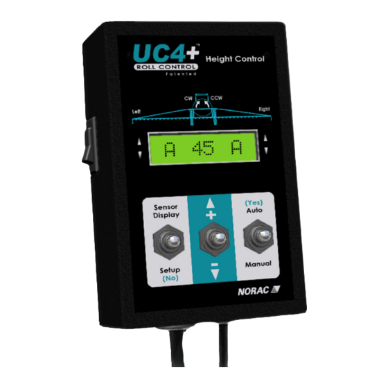
Operation 5.1 Basic UC4+ Operation Upon power-up a sequence of messages are temporarily displayed on the control panel LCD screen. The system is ready for use once the run screen is displayed. To access either the "SENSOR DISPLAY" or "SETUP" menus, ensure you are at the run screen. -
Page 11: Sprayer Switches
Viewing the Sensor or Target Height: When in manual mode the run screen shows the average of all the sensor heights. In automatic mode the number shown on the run screen is the target height. Toggle "SENSOR DISPLAY" to view the actual sensor heights. The left, right, and main (center) sensor heights are each displayed on a separate screen. -
Page 12: Main Menu Settings
5.3 Main Menu Settings Soil / Crop Mode: Soil mode configures the sensors to read the height from the spray nozzles to the ground, where as crop mode will read the height from the spray nozzles to the top of the crop canopy. To change between soil and crop mode, toggle "SETUP"... -
Page 13: Main Menu Map
5.4 Main Menu Map More Sensor Settings Tips Severe Terrain Mode Roll Information 11 () Center Height Right Height Left Height 90 89 Sensor Display Run Screen M 82 M Setup Sensi 5 Sensitivity Soil On Crop or Soil Mode Retune Hydraulics ReTune ? More... -
Page 14: Understanding The Uc4+ System
Understanding the UC4+ System The UC4+ Spray Height Control System will work well in most situations. As with any equipment, it is important that the operator remains alert at all times. There may be some situations and terrain where performance is limited and in these situations the operator must resume manual control of the booms. -
Page 15: Soil Mode And Crop Mode
6.4 Soil Mode and Crop Mode Height sensors use “smart sensor” technology, which take measurements from both the top of the crop canopy and from the soil surface. This allows the user to select either “Crop” or “Soil” mode. In “Soil” mode the target height is measured from the soil to the sprayer nozzle. In “Crop”... -
Page 16: Setup
Setup When the control panel is turned on for the first time, the UC4+ control panel guides the operator through the Automatic System Setup. Normally the UC4+ Spray Height Control System will automatically configure and calibrate itself to the sprayer. If this process does not produce the desired results, perform the Manual System Setup described in Section 7.3. - Page 17 operation. Changing the hydraulic flow controls after or during the system setup will affect the UC4+ performance. 7.1.2 Turn On the UC4+ Control Panel If this is the first setup for the panel, this process will begin automatically. If the panel was previously setup, you need to select "Install?"...
- Page 18 7.1.4 Wiring Test Press Left Up Use the sprayer's manual controls to move the left boom up. If the wrong boom moves or if the direction is incorrect, stop the setup. Consult the UC4+ Installation Manual to check the hydraulic plumbing and electrical wiring of your system.
- Page 19 7.1.5 Sensor Detect Level Booms at 35 inch Height Proceed? Position all boom sections such that the nozzles are 35 inches (90 cm) from the ground. Toggle "AUTO (YES)" to continue. Note: If you cannot get all the booms set to exactly 35 inches (90 cm), you can adjust the sensor height after you have finished the install.
- Page 20 7.1.6 Boom Geometry Tuning Exit Cab push boom tip near to ground & let go Exit the cab and manually push either boom tip down 1 – 3 feet (30 – 90 cm) for a moment and then let go. ...
- Page 21 7.1.8 System Testing M 39 M The run screen is shown above. It shows the system is in manual mode with an average height reading of 39 inches (100 cm). CAUTION In the following procedure, switch the control panel to manual mode immediately if the boom movements are erratic.
-
Page 22: Retune
7.2 Retune From time to time it may be necessary to recalibrate (Retune) the UC4+ electronics to your sprayer’s hydraulics. Examples of such times are: A hydraulic solenoid valve has been changed. The hydraulic pump has been changed or adjusted. ... -
Page 23: Manual Setup
7.3 Manual Setup The UC4+ Spray Height Control System will not operate in automatic mode until the system has been configured. It is recommended that the Automatic System Setup be used, but if necessary a manual system setup may be used. The manual system setup involves setting up each sensor (programming serial numbers and sensor locations) as well as tuning the hydraulic parameters manually. - Page 24 Navigating to the Sensor Menu: Ensure the UC4+ control panel is in manual mode, at the run screen. Navigate to the "More?" menu prompt in the SENSOR DISPLAY menu. Toggle "AUTO (YES)" to confirm. Navigate to the boom section you would like to change. Toggle "AUTO (YES)". The left channel menu prompts are shown below.
- Page 25 Calibrating the Sensor’s Height Reading (Zero Height): Ensure the sprayer boom is unfolded and the sensors are located over bare soil or gravel. Position the boom at a normal working height. Do not conduct this procedure over standing crop or tall grass/weedy areas. ...
- Page 26 7.3.2 Valve Tuning Each valve must be tuned correctly for optimum performance from the UC4+ Spray Height Control System. When setting up the valves, the sprayer booms must have room to move in their full range of motion. Make sure there are no obstructions, such as power lines, that the booms may come into contact with.
- Page 27 Automatic Dead Zone Calibration: Follow Section 7.1.1 (level booms, working RPM, etc.) before proceeding. Ensure the UC4+ control panel is in manual mode, at the run screen. Navigate to the "More?" menu prompt in the SETUP menu. Toggle "AUTO (YES)" to confirm.
- Page 28 Automatic Gain Calibration: Before tuning the gain setting, the dead zone for that function must be tuned. If the dead zone tuning has not been completed, follow the instructions for tuning a dead zone. Follow Section 7.1.1 (level booms, working RPM, etc.) before proceeding. ...
- Page 29 The change in height reading is live as long as you hold the "MANUAL" switch. Wait until the height reading has settled to a stable value and record this reading. This is your boom speed in inches per second (in/s) or mm per second (mm/s). ...
- Page 30 7.3.3 Boom Geometry Tuning (Push Test) If you would like to redo the push test, or if you have manually set up the system and need to calibrate the boom geometry you can manually launch the push test again. To Manually Launch the Boom Geometry Test: ...
- Page 31 7.3.4 Turning Booms Off or On You can turn UC4+ automatic height control off for each individual boom section. In automatic mode, boom sections that are turned off will not automatically adjust, and are indicated with a "D" in the run screen, as shown in Figure 11. This may be useful if you are mounting the main lift sensor directly behind a sprayer tire which can impair the main lift control when operating in crop mode.
-
Page 32: Quick Install
7.4 Quick Install The Quick Install feature of the UC4+ Spray Height Control System is designed to help diagnose problems that cannot be identified during the Automatic Setup. It will instantly setup the system with typical values for hydraulic calibration and sprayer geometry, based on the sprayer type selected. - Page 33 ACTIVE ROLL SYSTEM: Perform the Quick Install for the standard system as previously described. Roll OnA Navigate to the "Roll ?" menu prompt in the SETUP menu. Toggle "AUTO (YES)", and then change it to "Roll OnA" using the " +/- " switch. Toggle "AUTO (YES)" to confirm. ...
-
Page 34: Optional Kits
Optional Kits The kits shown below are optional add on kits for the UC4+ Spray Height Control System. These kits will help improve the performance for certain situations described below. 8.1 Severe Terrain Kit Additional sensors may be added to improve boom protection and system performance. ... -
Page 35: Roll Bias (Active Roll) Kit
8.3 Roll Bias (Active Roll) Kit Available on certain sprayer models (most sprayers with boom roll capability). Full boom roll is controlled actively together with wing tilt functions. Provides active isolation between the boom and sprayer, and increases reaction speed. ... -
Page 36: Options
Options 9.1 Headland Assist Headland Assist is used to raise the wings only or the entire boom at the end of the field for turning. This feature operates when the system is in automatic mode. This feature is enabled for certain sprayer types. The headland mode height can be changed. - Page 37 Setting Remote Switches Headland Assist Trigger Mode Rems Off Disabled Disabled Disabled Disabled Rems On Enabled Disabled Disabled Disabled Disabled Enabled Main Up / Down Main Lift Enabled Enabled Main Up / Down Main Lift Enabled Enabled Remote Auto Main Lift Disabled Enabled Main Up / Down...
-
Page 38: Remote Switches
Data" messages flashing in place of the sensor height readings. 9.4 High Oil Temperature Alarm The High Oil Temperature Alarm will sound if the Norac valve block reaches a temperature of 95° C. This alarm will only sound once and will not repeat. The alarm is re-enabled each time the automatic mode is entered. -
Page 39: Minimum Height Mode
9.6 Minimum Height Mode Minimum height mode is normally used only for systems with five sensors (severe terrain kit). Since the five sensor system has two wing sensors that average the height, it is possible to have a boom tip close to the ground while still maintaining an acceptable average height. The minimum height defines the lowest height in which a single sensor on the wings is allowed to ... -
Page 40: Maintenance
Replace the oil filter in the NORAC hydraulic manifold (PT# 104827) annually. If necessary, contact your NORAC dealer to have the sensors recalibrated or repaired. A typical sensor can operate three to ten years without requiring attention. -
Page 41: Troubleshooting
11 Troubleshooting 11.1 General Operation Boom does not appear to be level after system setup: The sensitivity setting may be too low. Check the sensor height readings, if it differs from the target height then try turning up the sensitivity. The default tolerance for a sensitivity setting of 5 is ±... -
Page 42: Sensors
11.2 Sensors Height or roll sensor appears not to work (displays "NC" or "No Comm"): "NC" or "No Comm" refers to no communication. This may be caused by a damaged or defective CAN-bus cable. Ensure all cables are connected correctly. The connections should be tight and free of corrosion. - Page 43 Sensor Swapping: Swapping Sensors is a useful procedure for determining whether a sensor error message (e.g. "LO NC") is due to the sensor or the wiring to the sensor. Note: A sensor may have power and emit a ticking sound, but have broken communication wire(s), which would cause this error.
-
Page 44: Hydraulics
Boom(s) will not raise or lower: Ensure there is hydraulic oil being supplied at the Norac valve block and that there is pressure at the pressure port. The hydraulics will not work if the pressure and tank lines are reversed. -
Page 45: Boom Stability
11.4 Boom Stability The boom is unstable in automatic mode: Ensure the sprayer’s boom suspension is operating correctly and moving freely. If the suspension is sticking or too loose the boom will be unstable. If the boom is unstable in manual mode, the height control system will not make it more stable. -
Page 46: Setup Messages
11.5 Setup Messages The following are descriptions of messages or problems that may be encountered during the automatic setup or retune. "Timeout": This message may occur if the system is trying to move a boom but does not see any change in the sensor heights. -
Page 47: Operational Messages
11.6 Operational Messages The following messages may appear during normal operation and may not indicate an error with the system. "NR" or "NoRdg": This indicates the sensor is not receiving a good reading. It is normal to see this message occasionally, however if the message is constantly displayed there may be a problem with a sensor. -
Page 48: Statement Of Limited Warranty
NORAC or its authorized dealer to the purchaser. Items include weighing systems, instrumentation, and control systems manufactured by NORAC. Auxiliary components not manufactured by NORAC such as tires, axles, pumps, or rebuilt parts are covered by a 6 month warranty only. -
Page 49: Sprayer Types
Rau Sprayers - Variable Geometry Type (Metric) Fast with Active Roll Rau Sprayers - Fixed Geometry Type (Metric) Fast OEM Style Install 5 Station (Norac Grip) Rogator Sprayer 64 and 74 Series Fast OEM Style Install 6 Station (Norac Grip) -
Page 50: Uc4+ Menu Structure
14 UC4+ Menu Structure... - Page 51 Canada NORAC Systems International Inc. Phone: (+1) 306 664 6711 Toll Free: 1 800 667 3921 Shipping Address: 3702 Kinnear Place Saskatoon, SK S7P 0A6 United States NORAC, Inc. Phone: (+1) 952 224 4142 Toll Free: 1 866 306 6722...
Need help?
Do you have a question about the UC4+ and is the answer not in the manual?
Questions and answers
How do I set roll control left side is lower than right on 100 foot boom
To adjust the roll control on the left side for the Norac UC4+ with a 100-foot boom:
1. Check the boom style:
- If it's a center pivot style boom (common for 100-foot booms), roll values should be around 70 to 120.
- If it's a trapeze style boom, values should be around 20 to 40.
2. Press and hold the "MANUAL" button from the run screen to view the roll values.
3. The left and right roll values should normally be within 10 of each other.
4. Adjust the roll gain settings based on boom speed:
- For example, if the boom speed is 10–15 inch/sec, set roll gain between 225 and a lower value depending on desired response.
Use the gain settings from the roll section:
- Roll speed 1–10 inch/sec: gain 254–225
- Roll speed 10–15 inch/sec: gain 225–...
Adjust the gain as needed to balance left and right roll values and maintain stability.
This answer is automatically generated
Not showing roll come on screen as * roll Then ends with 6 Absent
When the Norac UC4+ displays "* roll" and ends with "6 Absent," it means that the system is not receiving a good signal or reading from Sensor 6. This indicates that Sensor 6 may be disconnected, malfunctioning, or not properly aligned.
This answer is automatically generated