Norac UC4+ Operator's Manual
Spray height controller
Hide thumbs
Also See for UC4+:
- Operator's manual (51 pages) ,
- Installation manual (50 pages) ,
- Manual (31 pages)

Related Manuals for Norac UC4+


Summary of Contents for Norac UC4+
- Page 1 Spray Height Controller Operators Manual Version 6 - 2008 Improving the competitiveness of Industry and Agriculture through Precision Measurement...
- Page 2 Copyright ©2008 NORAC Systems International Inc. Reorder P/N: 446BC+MAN6+1 Revision A NOTICE NORAC Systems International Inc. reserves the right to improve products and their specifications without notice and without the requirement to update products sold previously. Every effort has been made to ensure the accuracy of the information contained in this manual.
-
Page 3: Table Of Contents
TABLE OF CONTENTS INTRODUCTION ....................1 OPERATOR SAFETY.....................2 GENERAL SYSTEM DESCRIPTION..............3 .................... 3 OFTWARE ....................4 ENSORS ....................6 ABLES ................... 6 ONTROL ANEL SYSTEM OPERATION...................7 ................7 OWER EQUENCE ................8 YPICAL PERATION UNDERSTANDING YOUR UC4+ SYSTEM ............13 ........... 13 NDERSTANDING ERFORMANCE SSUES... -
Page 4: Introduction
If you have any questions or comments regarding the operation of the UC4+ Spray Height Control system, please contact NORAC at any of the numbers below. If you require service, phone us or visit our web site for the location of the NORAC Service center nearest to you. -
Page 5: Operator Safety
OPERATOR SAFETY DANGER Always ensure that the UC4+ Spray Height Control system is powered down or in MANUAL mode: • Before leaving the operator’s seat • While the machine is not moving • When transporting the machine Under no circumstances should any service work be performed on the machinery while the UC4+ Spray Height Control system is in the AUTOMATIC mode. -
Page 6: General System Description
Version 1 (all revisions). All UC4+ control panels can have their software upgraded for a nominal fee. It is recommended that all panels with earlier software be updated to the current software version. Contact your local dealer or NORAC for more information. -
Page 7: Ensors
3.2 S ENSORS Three sensors are provided with your UC4+ boom control kit (with the exception of certain kits). The sensors use an ultrasonic signal to measure the distance to the ground, or the top of the crop. Three sensors are required to provide good overall height management of the boom. - Page 8 NORAC ultrasonic sensors are designed to work best in the brackets provided (Figure 2). If you decide to use a different style of sensor mount, you may limit the performance of the sensor and/or void your warranty. Further, it is important to follow the guidelines in the UC4+ Installation Manual for mounting the sensors.
-
Page 9: Cables
3.3 C ABLES The power cable supplies 12 volt D.C. negative ground power to the control panel and sensors. The system will function properly with a supply between 12 and 28 volts and may draw up to 10 amperes during normal operation. The UC4+ control panel contains intelligent valve drive circuitry that helps to protect the sprayer’s system against short circuits and other wiring problems. -
Page 10: System Operation
SYSTEM OPERATION This section outlines the UC4+ Spray Height Control system’s features and controls during field operation. Before you can operate your UC4+ Spray Height Control system in AUTO mode, it needs to be configured either automatically or manually. If your control panel shows the power up sequence below and will allow AUTO mode, it has been configured. -
Page 11: Typical Operation
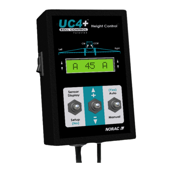
4.2 T YPICAL PERATION 4.2.1 Normal Operating Screen The Normal Operating Screen provides information pertaining to the height and mode of both booms. Figure 6 shows a typical Normal Operating Screen. LEFT BOOM RIGHT BOOM MAIN LIFT TARGET HEIGHT Figure 6 – Normal Operating Screen When a boom is in AUTO mode, indicated by an "A"... - Page 12 Table 3 – Main Menu Structure Navigating past the end of the menu will return the control panel to the Normal Operating Screen Toggle the "AUTO (YES)" switch to edit or view more sensor More ? settings. Displays diagnostics information used by technical staff. 88 () 67 Displays the current main lift height, in the selected units.
- Page 13 4.2.3 Using the Toggle Switches All functions on the UC4+ control panel are activated using its three toggle switches. To access either the SENSOR DISPLAY or SETUP menus, make sure you are at the Normal Operating Screen. To adjust the setting of individual menu items, use the "...
- Page 14 NOTE: The minimum height settings are adjustable. – If you wish to adjust them, please contact NORAC for details. You can also adjust your main boom target height by pressing the sprayer's main lift control switches. Each press of the up switch will increase the target height by one unit.
- Page 15 4.2.7 Changing the Sensitivity of the System The Sensitivity (Sensi) setting (Section 5.1.1) can be adjusted in both MANUAL and AUTO modes. Toggle the "SETUP (NO)" switch to view the current Sensi setting. While viewing this menu, toggle the "+/-" switch to adjust the value.
-
Page 16: Understanding Your Uc4+ System
NORAC as optional equipment. Contact NORAC or your sprayer dealer for more assistance. 5.1.2 Boom Reaction Time There are two key factors that determine how quickly your boom can react to changes in terrain. - Page 17 The second factor is the mechanical design of the sprayer. The Sensi setting does affect the reaction time of your boom – the higher the number the quicker the response. However, how high you can run the Sensi setting is determined to a large extent by mechanical issues related to the boom and sprayer.
- Page 18 Extra foam pieces are shipped with your kit. The transducer is a maintenance item and can be replaced at NORAC service locations. Transducers can last from three to ten years, depending on conditions. Refer to Section 7 on page 36 and the UC4+ Quick Guide for more maintenance information.
-
Page 19: Understanding Crop Mode And Soil Mode
5.2 U NDERSTANDING ODE AND A unique feature of UC4+ sensors is their ability to operate in CROP mode. In this mode the sensor will track the first available sonic target. That is, when positioned over standing crop, the sensor will return the average height of the heads in a circular area below the sensor. - Page 20 5.2.2 Boom Stability in Crop In general the top of the crop is a more inherently variable target than soil. To put it simply, given identical control settings, your height control would be more active when operating in CROP mode than in SOIL mode. To allow for this, many settings are customized automatically when you change modes on the UC4+ control panel.
-
Page 21: System Setup
SYSTEM SETUP Before the UC4+ boom height control system will function properly, some information about the sprayer and connected sensors is necessary. When the control panel is turned on for the first time, the UC4+ control panel guides the operator through the Automatic System Setup. This procedure is described in Section 6.1. - Page 22 WARNING!: • AT POINTS DURING THE SYSTEM SETUP (RETUNE) ALL BOOM SECTIONS NEED TO MOVE. • PERSONNEL AND EQUIPMENT MUST BE CLEAR OF ALL BOOMS. • MAKE SURE ALL BOOMS HAVE ROOM TO LIFT FULLY AND ARE CLEAR OF POWER LINES. 6.1.1 STEP 1: Prepare the Equipment (1) Unfold the sprayer in a location that is relatively level, and where the sensors are over bare soil or gravel.
- Page 23 6.1.4 STEP 4: Turn On the UC4+ Control Panel. If this is the first setup for the panel, this process will begin automatically. If the panel was previously setup, you need to select "Install?" from the SETUP menu to initiate Automatic System Setup.
- Page 24 6.1.6 STEP 6: Wiring Test * ↓ ↓ Press Left Up ⇒ ⇒ • Use the sprayer's manual controls to move the left boom up. • If the wrong boom moves or if the direction is incorrect, stop the setup. Consult the UC4+ Installation Manual to check the hydraulic plumbing and electrical wiring of your system.
- Page 25 6.1.7 STEP 7: Sensor Detect ↓ ↓ ↓ Level booms at 35 inch ⇒ ⇒ ↓ height Proceed? ⇒ ⇒ • If you have main boom roll control, manually level the boom. • Position all other boom sections such that the nozzles are 90 cm (35 inches) from the ground.
- Page 26 6.1.8 STEP 8: Boom Geometry Tuning • Do not activate any hydraulic functions during this step. ↓ ↓ ↓ Release Switch ⇒ • Release the "AUTO (YES)" switch to continue. ↓ ↓ ↓ Exit cab push boom tip ⇒ ⇒ ↓...
- Page 27 ↓ ↓ ↓ Hold AUTO until ⇒ ⇒ ↓ Done ⇒ • Hold the "AUTO (YES)" switch to continue the boom geometry tuning. If "AUTO (YES)" is released before "Done" is displayed, simply toggle and hold again to continue the procedure. •...
- Page 28 6.1.9 STEP 9: Control System Test ↓ M 84 M • Normal Operating Screen is shown above. CAUTION!: IN THE FOLLOWING PROCEDURE, SWITCH THE CONTROL PANEL TO MANUAL MODE IMMEDIATELY IF THE BOOM MOVEMENTS ARE ERRATIC. • Toggle "AUTO (YES)" to start AUTO mode. Observe the behavior of the booms while correcting to the target height.
-
Page 29: R E Tune
6.2 R From time to time it may be necessary to recalibrate (ReTune) the UC4+ electronics to your sprayer’s hydraulics. Examples of such times are: • when a hydraulic solenoid valve is changed • when the hydraulic pump is changed or adjusted •... -
Page 30: Manual System Setup
6.3 M ANUAL YSTEM ETUP The UC4+ control panel will not permit AUTO mode unless the system has been completely configured by either the Automatic System Setup or Manual System Setup. Manual Setup will require setting up each sensor (programming serial numbers and sensor locations) as well as tuning the hydraulic parameters manually. - Page 31 6. Use the "+" switch to toggle through a list of available sensor serial numbers. If you wish to turn this sensor off, toggle "–" switch. 7. When the desired serial number is shown, toggle "AUTO (YES)" switch to confirm. 8.
- Page 32 4. At the "Main On" prompt, toggle the " +/- " switch to change to "Main Off". ↓Main Off↓ 5. Toggle and hold "SETUP (NO)" switch for two seconds to return to the Normal Operational Screen. B. Adjusting the Sensor Offset To compensate for the lack of crop in the “wheel track”, adjust the main lift sensor’s height reading offset (zero height) so that the sensor will read higher to match the average height of your crop.
- Page 33 6.3.2 Setting Up Hydraulic Valves There are two key settings for each valve direction (for example, the left up direction). These settings are valve DeadZone, "DZ", and valve GAIN, "KP". The DeadZone ("DZ") setting represents the size of electrical signal required at the solenoid valve to cause a boom speed of one inch per second.
- Page 34 6.3.3 Valve DeadZone Test 1. Follow the steps, 6.1.1 to 6.1.3 (level booms, working RPM, etc.), before proceeding. 2. Ensure the UC4+ control panel is in MANUAL mode, at the Normal Operating Screen. 3. Navigate to the "More ?" menu prompt in the SETUP menu Toggle the "AUTO (YES)"...
- Page 35 6.3.4 Valve Gain Test 1. Follow the steps, 6.1.1 to 6.1.3 (level booms, working RPM, etc.), before proceeding. 2. Ensure the UC4+ control panel is in MANUAL mode, at the Normal Operating Screen. 3. Navigate to the "More ?" menu prompt in the SETUP menu Toggle the "AUTO (YES)"...
- Page 36 Set the Gain value using the " +/- " switch using the tables • below as a guideline. Right and left Gain settings are polarized for direction as shown in Table 6. NOTE: Gain values depend on many more factors than just speed, and therefore are best set automatically or by an experienced operator.
- Page 37 Remote control of the AUTO and MANUAL modes may be wired to the control panel. This feature allows the operator to control the mode of the UC4+ Spray Height Control system from an external switch or controller. Contact NORAC for further information concerning wiring and enabling Remote Switch control.
-
Page 38: Quick Install
6.4 Q UICK NSTALL The Quick Install feature of the UC4+ Spray Height Control system is designed to help diagnose problems that cannot be identified during the Automatic Setup. It will instantly setup the system with typical values for valve calibration and sprayer geometry, based on the sprayer type selected. Perform the following procedure for a Quick Install ♦... -
Page 39: Maintenance
Figure 9 – Protective Foam Shield At the End of a season: Remove the sensors and store inside. Replace oil filter in the NORAC hydraulic manifold (PT#: 104827) annually. Replace ultrasonic transducer as needed. Over time, performance of the inexpensive transducer element may become degraded from airborne contamination (typical life is 3-10 years). -
Page 40: Troubleshooting
TROUBLESHOOTING • This section discusses common symptoms and suggested solutions when the UC4+ control system is being installed or operated. 8.1 G ENERAL PERATION 8.1.1 • LCD screen does not light up • System resets itself when a boom valve is turned on Possible Cause(s) Suggested Solution(s) a) Inadequate power... - Page 41 NOTE: appropriately for the sprayer ex. IN5408 This is similar to when the for a 3 Amp or smaller coil). operator momentarily presses Contact NORAC for more information. main up/down buttons to increase/decrease the spray height setpoint (Section 4.2.5). 8.1.5 •...
- Page 42 8.1.6 • Boom does not appear to be sufficiently level after System Setup Possible Cause(s) Suggested Solution(s) a-1) Check the average nozzle height on LCD a) Sensitivity (Sensi) screen in MANUAL mode. setting is low a-2) If the displayed heights differ from the target heights (setpoints), check Sensi setting and adjust it, if necessary.
-
Page 43: Ensor Elated Ssues
8.2 S ENSOR ELATED SSUES 8.2.1 • Display stuck at “"Mot’n Dly" or "KP Stp 9" Possible Cause(s) Suggested Solution(s) a) Sensor is too close to a) Move the sensor to a better location. It the boom should be 25cm (9 inches) in front of and 25cm (9 inches) above the spray nozzle. - Page 44 8.2.3 • Invalid sensor measurement: Displaying "NR" Possible Cause(s) Suggested Solution(s) a) Sensor is out of range a-1) Move the boom(s) until sensor(s) is or reading a target between 80 and 150cm (30 and 60 inches) closer than 18cm above the ground. (7 inches) a-2) Check sensor alignment (Section 8.2.7).
- Page 45 8.2.5 • Sensor not working: Displaying "###" or " " (too high or low) Possible Cause(s) Suggested Solution(s) a) Boom section is too a) Lower the boom section. high ("###"). NOTE: The sensor is reporting a reading that has too many digits to display on the LCD screen.
- Page 46 8.2.7 Sensor Alignment Proper sensor alignment is critical in order for UC4+ performance. The majority of problems reported by operators in the field are due to improper sensor mounting. Wing Sensors • When the boom is in its lowest position, the sensor mouth must be 22cm (9 inches or more above the spray nozzles.
-
Page 47: Hydraulic Related Issues
Tank (“T”) in order to create sufficient the check valves in back-pressure to activate the pilot-operated the NORAC valve check valves in the NORAC valve block. block NOTE: Some Single Acting valve systems only d) Poor cable... - Page 48 Some single acting circuits may require pressure to activate orifices to be placed in the “A” lines going the pilot-operated to the tank. check valves in the NORAC valve block 8.3.3 • "Timeout!" error during System Setup Possible Cause(s) Suggested Solution(s)
- Page 49 The boom lower line(s) connect(s) to the “A” port(s) on the NORAC valve block. • The Tank and Pressure lines connect to the Tank (“T”) port and Pressure (“P”) port on the NORAC valve block, respectively. 8.3.5 • Boom(s) creep up or down in MANUAL mode •...
- Page 50 Plumbing single b) Contact NORAC for more information. acting systems as double acting with both A ports orificed may reduce heating...
-
Page 51: Boom Instability And Main Lift
8.4 B NSTABILITY AND 8.4.1 • Erratic or “jumpy” boom behavior (in CROP mode) • Bouncing boom(s) Possible Cause(s) Suggested Solution(s) a) Sensor readings from a) Tune the hydraulic system properly. the crop canopy are NOTE: This symptom occasionally appears on the main lift control. -
Page 52: System Messages
SYSTEM MESSAGES 9.1 S ETUP ESSAGES • During an Install or ReTune if any of the following messages appear on the LCD screen, the system will halt any valve action and wait for operator acknowledgement. • Some of these messages appear after the operator is prompted to "Release"... - Page 53 Required Action Boom moves in the Wiring or hydraulic Follow 8.3.4, 8.3.1 d). wrong direction. plumbing problem. Extremely under-damped Add mechanical damping to boom. the boom and/or consult NORAC. ↓ ↓ ↓ ↓ ↓ ↓ TooHigh! TooLow! Retry ? ⇒...
-
Page 54: Operational Messages
9.2 O PERATIONAL ESSAGES • The following messages are non-critical messages that appear on the LCD screen when scrolling through the SENSOR DISPLAY menu from the Normal Operating Screen. Scrolling through the height display screens is a good place to start when troubleshooting because sensor errors will be displayed here. - Page 55 ↓ Disabled Explanation Possible Causes Required Action Access to System Setup Access to these features was Contact NORAC for instructions to features (Install, enable feature access. disabled by installer to avoid ReTune) have been unintentional system changes. locked out. ↓...
-
Page 56: Statement Of Limited Warranty
NORAC. Auxiliary components not manufactured by NORAC such as tires, axles, pumps, or rebuilt parts are covered by a 6 month warranty only. NORAC will repair free of charge items returned within the warranty period to one of NORAC’s authorized Service Centers. -
Page 57: Sprayer Types
RHS Bestway 1200/1600 with no Main Lift Valve Raptor Spray Coupe 7000 Series Summers Pull-type Sprayer Specialties Top Air Wilmar 8100/8500 Wilmar 8400/8600 Generic Active Roll Type OEM Style ( Norac Grip, Wiring) Generic Active Roll Type Retrofit Table 12 – Sprayer Types... -
Page 58: Menu Structure
MENU STRUCTURE Table 13 – Main Menu Structure Navigating past the end of the menu will return the control panel to the Normal Operating Screen Toggle the "AUTO (YES)" switch to edit or view more sensor More ? settings. Displays diagnostics information used by technical staff. 88 () 67 Displays the current main lift height, in the selected units. - Page 59 Table 14 – Full Menu Structure Section 4.2.5 Units cm Section 6.3.1 Section 6.3.1 Other ? BFh- 215 RIht 30 Roll 2080 MLht 27 3571 Main 3567 ROht 32 Right ? 3570 Section 6.3.1 SENSOR Left DISPLAY LIht 28 3569 More LOht 31 66 () 58...
- Page 60 Canada NORAC Systems International Inc. CALL TOLL FREE: 1-800-667-3921 (306)664-6711 SHIPPING ADDRESS: 3702 Kinnear Place Saskatoon, SK S7P 0A6 United States Norac, Inc. CALL TOLL FREE: 1-866-306-6722 (763)786-3080 SHIPPING ADDRESS: 1290 Osborne Rd NE, Suite F Fridley, MN 55432-2892...
Need help?
Do you have a question about the UC4+ and is the answer not in the manual?
Questions and answers