Norac UC4+ Installation Manual
Spray height controller for rhs bestway 1200/1600
Hide thumbs
Also See for UC4+:
- Operator's manual (60 pages) ,
- Installation manual (50 pages) ,
- Manual (31 pages)

Subscribe to Our Youtube Channel
Related Manuals for Norac UC4+


Summary of Contents for Norac UC4+
- Page 1 Spray Height Controller RHS BestWay 1200/1600 Installation Manual Improving the competitiveness of Industry and Agriculture through Precision Measurement...
- Page 2 Reorder P/N: UC4+BC+RH1-INST Rev B (RHS Bestway) NORAC Systems International Inc. reserves the right to improve products and their specifications without notice and without the requirement to update products sold previously. Every effort has been made to ensure the accuracy of the information contained...
-
Page 3: Table Of Contents
TABLE OF CONTENTS INTRODUCTION...........................1 GENERAL SYSTEM DESCRIPTION ....................2 PARTS LISTS............................3 INSTALLATION PROCEDURE......................7 ........................7 ENSOR NSTALLATION ....................8 ENSOR NSTALLATION ......................10 YDRAULIC NSTALLATION 4.3.1 Valve Mounting ........................10 4.3.2 Hydraulic Plumbing ........................11 ......................12 LECTRICAL NSTALLATION .....................14 OMPLETING THE ACTORY NSTALL END USER INSTALLATION ......................15 ELECTRICAL REFERENCE –... -
Page 4: Introduction
INTRODUCTION Congratulations on your purchase of the NORAC UC4+ Spray Height Controller. This system is manufactured with top quality components and is engineered using the latest technology to provide operating features and reliability unmatched for years to come. When properly used the system can provide protection from sprayer boom damage, improve sprayer efficiency, and ensure chemicals are applied correctly. -
Page 5: General System Description
However, NORAC cannot guarantee all Once hydraulics have been parts fit as intended due to the variations disconnected you must complete the of the sprayer by the manufacturer. -
Page 6: Parts Lists
HYDRAULICS FITTING KIT - RH1 M01A 446BC+MAN6-1 MANUAL UC4+ BOOM CONTROL 2008 OPERATORS SMALL BOOKLET M01B 446BC+MAN6-2 MANUAL UC4+ BOOM CONTROL 2008 QUICK REFERENCE SMALL BOOKLET UC4+BC+RH1-INST MANUAL INSTALLATION UC4+ RHS BESTWAY 1200, 1600 44933S VALVE BLOCK ASSEM UC4-BC 2-STATION CC/LS VARIABLE RATE... - Page 7 Table 2 - 44865-27 - Hydraulics Fittings Kit (Rev B) Item Part Number Name Quantity Picture 101775 FEMALE PIPE THREAD COUPLER - 6FPT 102559 MALE PIPE THREAD ADAPTER - 6MP 6MP 103345 MALE TO FEMALE ADAPTER - 6MB 6FJX90 103312 MALE ADAPTER - 6MB 6MJ 104369 PLUG - 6MBP...
- Page 8 The parts that come with your UC4+ System are shown below in their general installation configuration. Figure 2 – UC4+ Spray Height Controller Components...
- Page 9 Figure 3 – Hydraulic Plumbing Schematic...
-
Page 10: Installation Procedure
INSTALLATION PROCEDURE 4.1 S ENSOR NSTALLATION Avoid mounting sensors in locations where they may read To correctly mount the sensor brackets, from parts of the boom as the bracket mounting adapter will most shown in Figure 5. likely be used. A completely assembled sensor bracket, with mounting adapter is shown in Figure 4. -
Page 11: Main Lift Sensor Installation
The General Mounting Rules for UC4+ Ultrasonic Sensors, from the previous section, must be followed. Ultrasonic Acoustic Cone Figure 6 - Sensor mounting guidlines Figure 8 – Main Lift Sensor Bracket Mounting Position 4.2 M ENSOR NSTALLATION 3. Mount the sensor onto the sensor 1. - Page 12 3 SENSOR SYSTEM 5 SENSOR SYSTEM Figure 10 – Sensor Serial Number Installation Location...
-
Page 13: Hydraulic Installation
4.3 H 5. Mount the NORAC valve (V01) on YDRAULIC NSTALLATION the sprayer using the valve mounting 4.3.1 Valve Mounting bracket (B10). 1. On a clean surface remove all plastic 6. As shown in Figure 13, screw short plugs from the NORAC hydraulic side of the threaded rods into the Valve (V01) (Figure 11). -
Page 14: Hydraulic Plumbing
Figure 3. 2. When plumbing, the “raise” lines must be connected to the “B” ports of the NORAC valve block. There must be a 1/32” orifice inline with each accumulators, as shown in the plumbing schematic (Figure 3). -
Page 15: Electrical Installation
4.4 E LECTRICAL NSTALLATION Figure 14 – Cable Configurations: Rear of the sprayer 1. Route C11 to the rear of the sprayer, in the vicinity of the valve block. Note that the 16-pin AMP plug provides the hitch connection. 2. Connect the 3-pin shroud on the generic interface cable (C13) to the mating 3-pin tower on C11. - Page 16 6. Install the square DIN connectors 7. Connect the sensor branch cable from C03 onto each NORAC valve (C02) to the 4-pin AMP plug on as shown in Figure 15. C11. connectors on the valve cable are 8. Route the sensor branch cable (C02) marked RIGHT UP, LEFT UP, to the wing and main sensors.
-
Page 17: Completing The Factory Install
“YES” to select the RH1 type, hold manufacturer’s boom controls. The the toggle switch towards “YES” NORAC Control Panel (Item E01) (for several seconds) until the word does not need to be powered up for “SENSOR” appears on the UC4+ the original switches to function. -
Page 18: End User Installation
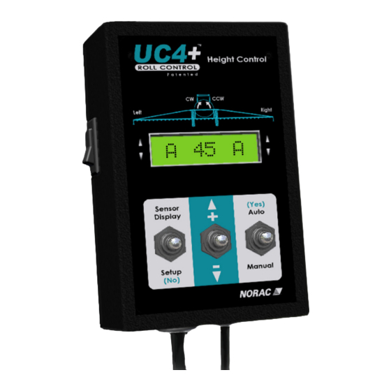
END USER INSTALLATION 1. Install the UC4+ Control Panel (E01) in the cab of the sprayer. Mount the panel where it will be clearly visible and within easy reach of the operator. A good spot to mount the UC4+ control panel is on the right hand side of the cab to the Roll Over Protection Bar. - Page 19 Figure 17 – Cable Configurations: C10, C10A and C11 2. Connect the power cable (C10) to 5. For optimal performance of the the UC4+ Control Panel in the UC4+ Spray Height Control system, sprayer cab. Ensure that both plugs there should be very little play at the (P16A and P4) are connected to the hitch clevis.
-
Page 20: Electrical Reference - Cable Drawings
ELECTRICAL REFERENCE – CABLE DRAWINGS 6.1 I C02: 44668 – S ENSOR RANCH ABLE 6.2 I C03: 44656 – V ALVE ABLE ARIABLE... -
Page 21: Item C10: 44650-39 - Cable Power Generic
6.3 I C10: 44650-39 – C ABLE OWER ENERIC... -
Page 22: Item C10A: 44650-03 Cable Power Version 3 ( Ag - Pull Type )
6.4 I C10A: 44650-03 C ABLE OWER ERSION PULL TYPE... -
Page 23: Item C11: 44651-03 Cable Extension Valve Generic
6.5 I C11: 44651-03 C ABLE XTENSION ALVE ENERIC... -
Page 24: Item C13: 44658-57 Interface Cable Generic Directional Valves
6.6 I C13: 44658-57 I NTERFACE ABLE ENERIC IRECTIONAL ALVES... - Page 25 Canada NORAC Systems International Inc. CALL TOLL FREE: 1-800-667-3921 (306)664-6711 SHIPPING ADDRESS: 3702 Kinnear Place Saskatoon, SK S7P 0A6 United States Norac, Inc. CALL TOLL FREE: 1-866-306-6722 (763)786-3080 SHIPPING ADDRESS: 1290 Osborne Rd NE, Suite F Fridley, MN 55432-2892...
Need help?
Do you have a question about the UC4+ and is the answer not in the manual?
Questions and answers