Norac UC4+ Quick Manual
Spray height controller
Hide thumbs
Also See for UC4+:
- Operator's manual (60 pages) ,
- Installation manual (50 pages) ,
- Manual (31 pages)

Related Manuals for Norac UC4+


Summary of Contents for Norac UC4+
- Page 1 Spray Height Controller Quick Guide Version 6 - 2008 Improving the competitiveness of Industry and Agriculture through Precision Measurement...
- Page 2 Copyright ©2008 NORAC Systems International Inc. Reorder P/N: 446BC+MAN6-2 Revision B NOTICE NORAC Systems International Inc. reserves the right to improve products and their specifications without notice and without the requirement to update products sold previously. Every effort has been made to ensure the accuracy of the information contained in this manual.
-
Page 3: Table Of Contents
TABLE OF CONTENTS INTRODUCTION ....................1 OPERATOR SAFETY.....................2 BASIC UC4+ OPERATION..................3 ................. 4 ............. 5 RESS UNCTIONS .............. 6 ORMAL PERATING CREEN ........7 HANGING TO UTOMATIC OR ANUAL ..............7 DJUSTING THE ETPOINT ..........8 IEWING THE CTUAL EIGHT ........... 9 HANGING THE YSTEM ENSITIVITY... -
Page 4: Introduction
This guide is based on UC4+ software Version 6 Phone: 1-800-667-3921 in Canada (Toll Free) 1-866-306-6722 in the United States (Toll Free) 0-800-404-8389 in the United Kingdom (Toll Free) 1-306-664-6711 all other regions E-mail: service@norac.ca Web Site: www.norac.ca... -
Page 5: Operator Safety
OPERATOR SAFETY DANGER Always ensure that the UC4+ Spray Height Control system is powered down or in MANUAL mode: • Before leaving the operator’s seat • While the machine is not moving • When transporting the machine Under no circumstances should any service work be performed on the machinery while the UC4+ Spray Height Control system is in the AUTOMATIC mode. -
Page 6: Basic Uc4+ Operation
BASIC UC4+ OPERATION • Upon power-up a sequence of messages are temporarily displayed on the control panel LCD screen. If the system is running in metric, METRIC will be displayed briefly on the screen during set up. - The system is ready for use once the Normal Operating Screen (Figure 1) is displayed. -
Page 7: Main Menu Map
3.1 M Sensor Settings (Operator Manual) More ? Diagnostic Information 88 () 67 Center Height (sec. 3.6) Right Height (sec. 3.6) Left Height (sec. 3.6) Main Operating Screen Sensitivity (sec. 3.7) Sensi 5 Crop or Soil Mode (sec. 3.8) Soil ON Retune Hydraulics (sec. -
Page 8: Press -And -Hold Functions
3.2 P RESS UNCTIONS Alarm: Pressing and holding SENSOR DISPLAY will enable/disable the Alrm On alarm. If enabled, the alarm will sound if an ultrasonic sensor has lost a reading. The alarm is defaulted OFF. Main Operating Screen Valve and Air Temperature: Pressing and holding SETUP will cycle the display between the valve block temperature (VT) and the air... -
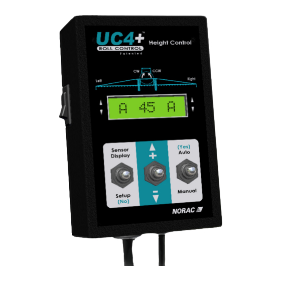
Page 9: Normal Operating Screen
3.3 N ORMAL PERATING CREEN • In AUTOMATIC mode the digits represent average target boom height in the selected units (cm or inches) • In MANUAL mode the digits represent average actual boom height in the selected units Table 1 – Examples of Normal Operating Screens LCD Display Description In AUTO mode, target average height is 89 cm (or inches... -
Page 10: Changing To Automatic Or Manual Mode
3.4 C HANGING TO UTOMATIC OR ANUAL • From the Normal Operating Screen toggle the control panel "AUTO" switch to change between MANUAL and AUTO modes. • In MANUAL mode, the boom may be controlled as usual with the boom control switches on the sprayer’s multifunction handgrip. •... -
Page 11: Iewing The Ctual Oom Eight
3.6 V IEWING THE CTUAL EIGHT • Toggle the "SENSOR DISPLAY" switch to view actual boom heights. • The left, right, and main (center) boom heights are each displayed on a separate screen. If there are 2 sensors on each wing, both sensor heights will be displayed on the same screen. -
Page 12: Hanging The Ystem Ensitivity
3.7 C HANGING THE YSTEM ENSITIVITY A sensitivity setting of 5 (default setting). Sensi • Toggle the "SETUP” switch to view the current Sensi setting. • While viewing this menu, toggle the " +/- " switch to adjust the Sensi value. •... -
Page 13: Performing A R E Tune
3.9 P ERFORMING A NOTE: Sensors are not adjusted or calibrated by performing a ReTune. A retune recalibrates hydraulic valve parameters. 3.9 .1 P e rfo rm a sy ste m R e Tun e whe n: • When a hydraulic solenoid valve is changed. •... -
Page 14: Menu Structure
MENU STRUCTURE Units cm Other ? BFh- 215 RIht 30 Roll 2080 MLht 27 3571 Main 3567 ROht 32 Right ? 3570 SENSOR Left DISPLAY LIht 28 3569 More LOht 31 66 () 58 3568 55 56 55 55 M 55 M Sensi 5 Left Soil On... -
Page 15: Statement Of Limited Warranty
NORAC. Auxiliary components not manufactured by NORAC such as tires, axles, pumps, or rebuilt parts are covered by a 6 month warranty only. NORAC will repair free of charge items returned within the warranty period to one of NORAC’s authorized service centers. - Page 16 Canada NORAC Systems International Inc. CALL TOLL FREE: 1-800-667-3921 (306)664-6711 SHIPPING ADDRESS: 3702 Kinnear Place Saskatoon, SK S7P 0A6 United States Norac, Inc. CALL TOLL FREE: 1-866-306-6722 (763)786-3080 SHIPPING ADDRESS: 1290 Osborne Rd NE, Suite F Fridley, MN 55432-2892...
Need help?
Do you have a question about the UC4+ and is the answer not in the manual?
Questions and answers