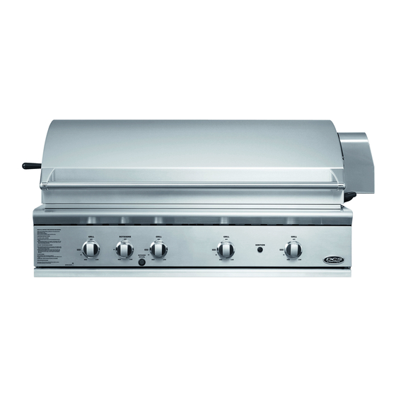
DCS BH1 series Installation And User Manual
Professional grill.
36 & 48 inch
Hide thumbs
Also See for BH1 series:
- Installation manual (2 pages) ,
- Installation manual/user manual (84 pages) ,
- Installation instructions and user manual (80 pages)

Related Manuals for DCS BH1 series


Summary of Contents for DCS BH1 series
- Page 1 PROFESSIONAL GRILL 36 & 48" BH1 models LE GRIL PROFESSIONNEL Modèles 36 et 48" BH1 INSTALLATION GUIDE / USER GUIDE GUIDE D’INSTALLATION / GUIDE D’UTILISATION US CA...
- Page 2 WARNING! If the information in this manual is not followed exactly, a fire or explosion may result causing property damage, personal injury or death. DO NOT SPRAY AEROSOLS IN THE VICINITY OF THIS APPLIANCE WHILE IT IS IN OPERATION. DO NOT USE OR STORE FLAMMABLE MATERIALS IN OR NEAR THIS APPLIANCE.
-
Page 3: Table Of Contents
CONTENTS Safety and warnings Grill models Product dimensions Installation Locating grill / built-in clearances Built-in construction details Gas hook-up Leak testing Burner adjustment Radiant assembly Griddle plate Installer checklist Using the grill Lighting instructions Grilling Using the rotisserie Care & maintenance Troubleshooting Service Warranty... - Page 4 DO NOT discard any packing material (box, pallet, straps) until the unit has been inspected. Inspect the product to verify that there is no shipping damage. If any damage is detected, call the shipper and initiate a damage claim. DCS by Fisher & Paykel is not responsible for shipping damage.
- Page 5 SAFETY AND WARNINGS To reduce the risk of fire, electrical shock, injury to persons, or damage when using the appliance, follow the important safety instructions listed below: WARNING! Hot Surface Hazard Accessible parts may become hot during use. Do not touch surface units or areas near units of the grill. Hood must be opened before lighting the grill.
- Page 6 SAFETY AND WARNINGS IMPORTANT SAFETY INSTRUCTIONS! Do not try lighting this appliance without reading the “LIGHTING INSTRUCTIONS” section of this manual (page 24). This grill must be installed according to these instructions and in compliance with the requirements of the current version of AS/NZS 5601.1, local authority, gas, electricity, and any other statutory regulations.
- Page 7 SAFETY AND WARNINGS IMPORTANT SAFETY INSTRUCTIONS! Keep the area surrounding the grill free from combustible materials, trash, or combustible fluids and vapours such as gasoline or charcoal lighter fluid. Do not obstruct the flow of combustion and ventilation air. ...
-
Page 8: Grill Models
GRILL MODELS BGB48-BQAR BGB48-BQR BGB36-BQAR... -
Page 9: Product Dimensions
PRODUCT DIMENSIONS BGB48-BQAR Model Illustrated BGB 48 BQAR BGB 48 BGB 36 PRODUCT DIMENSIONS Overall height of grill Overall width of grill 1217 1217 Overall depth of grill (excluding handle and dials) Depth of chassis Height of chassis Height of hood Overall width of grill with 1381 1386... -
Page 10: Installation
INSTALLATION Locating Grill/Built-in Clearances IMPORTANT! Tools required: Phillips screwdriver. Before installation, remove shipping brackets from the grill. To do so, loosen the four screws on the bottom sides of the grill which hold the brackets to the grill. Slide the shipping brackets off and retighten the screws. - Page 11 INSTALLATION Locating Built-in Clearances IMPORTANT! Never use the grill in windy conditions. If located in a consistently windy area (oceanfront, mountaintop, etc.) a wind break will be required. Always adhere to the specified clearances as defined in the “INSTALLATION” section of this manual. GRILL EXHAUST EXHAUST EXHAUST...
- Page 12 INSTALLATION Locating Built-in Clearances This appliance shall only be used in an above ground open-air situation with natural ventilation, without stagnant areas, where gas leakage and products of combustion are rapidly dispersed by wind and natural convection. Any outdoor enclosure in which the appliance is used shall comply with one of the following: ...
- Page 13 INSTALLATION Locating Built-in Clearances Clearances to non-combustible construction* A minimum of 76mm clearance from the back of the grill to non-combustible construction is required for the purpose of allowing the hood to open fully. There should be a minimum clearance of 610mm from the top of the grill lid while it is open to allow for exhaustion of heat.
- Page 14 If the grill is to be placed into a combustible enclosure, an approved insulated jacket is necessary. Insulated jackets are available from your dealer. Use only the DCS by Fisher & Paykel insulated jacket which has specifically been designed and tested for this purpose. Review the detail drawing shown (Fig.
-
Page 15: Built-In Construction Details
INSTALLATION Built-in Construction Details Standard layout for non-combustible cavity IMPORTANT! If installing the grill into a non-combustible enclosure, all combustible construction must still be outside the 310mm clearance zone. If your island is made of stucco over the top of wooden studs, the wood cannot be inside the 310mm clearance zone to combustible, even though the stucco is what is touching the grill area. - Page 16 INSTALLATION Built-in Construction Details Standard layout for cavity including insulated jacket Note: 102 x 102mm opening for gas supply line. Opening for access to gas cylinder or shut off valve. Note: vents are to be located at the left, right and rear of the enclosure.
-
Page 17: Gas Hook-Up
The gas fittings and hose assembly are compatible with the gas supply system and is able to deliver the maximum gas rating requirement of the DCS Outdoor Grill. All gas installation works are carried out in accordance the the AS/NZS Gas Installations Standard AS5601 and other applicable Standards. - Page 18 INSTALLATION Gas Hook-up Natural Gas Hook-up IMPORTANT! Where the appliance is intended to be permanently connected to a reticulated supply of gas, the appliance inlet connection shall have a thread in accordance with AS ISO 7.1. For grills mounted on a mobile cart and being connected to a reticulated supply of Natural gas, the installer must ensure that a restraining device that is no longer than 80% of the length of the hose is fitted with an eyebolt within 50mm of an external quick connect device, (as required by the current version of AS/NZS 5601.1) in order to prevent tension on the flexible hose in case the...
- Page 19 INSTALLATION Gas Hook-up LPG Gas Hook-up Grills set for use with LPG gas come equipped with a high capacity hose/regulator assem bly for connection to a standard 9 kg LPG POL cylinder. The LPG cylinder is not included. Connection: 1/2” NPT male with a 3/8” Flare adapter (included). LPG Hose with a POL fitting and fittings are included.
- Page 20 If you intend to operate your built-in grill on LPG gas utilising a minimum 9 kg cylinder, then the built-in LPG cylinder restraint must be installed prior to initial use of the grill. If you do not have one please contact DCS by Fisher & Paykel for information on obtaining one. See section ‘Service’ for contact details.
- Page 21 INSTALLATION Gas Hook-up 1 Place the tank restraint in the island and 2 Once located, secure to the bottom of the locate within the recommended area. island using all eight hole locations provided on the restraint. Wood screws can be used for wooden floors or 1/4 inch diameter anchor screws or bolts may be used if the floor is concrete or masonry.
-
Page 22: Leak Testing
INSTALLATION Leak Testing IMPORTANT! Gas leak testing must be carried out by a qualified technician. Do not use the grill until all connections have been checked and do not leak. Check all gas supply fittings for leaks before each use. Keep a spray bottle of soapy water near the gas supply shut-off valve. -
Page 23: Burner Adjustment
INSTALLATION Burner Adjustment Grill burner air adjustment Each grill burner is tested and adjusted at the factory prior to shipment; however, variations in the local gas supply or a conversion 10mm from one gas to another may make it necessary to adjust the burners. 38mm The flames of the burners (except the rotisserie burner) should be visually checked and compared to that of the drawing in Fig.16. -
Page 24: Radiant Assembly
INSTALLATION Radiant Assembly Installing the grease shields The grease shields (two per burner) help deflect any grease drippings away from the grill burner ports, preventing the ports from getting clogged. They come packed with the other accessories, in a separate bag. Unpack the grease shields and position them on the pins above the grill burners (two per burner), as shown in Fig. -
Page 25: Griddle Plate
INSTALLATION Griddle Plate Note: the griddle plate is not supplied with the grill but may be purchased separately as an optional accessory. To purchase a griddle plate, contact Customer Care. See section ‘Service’ for contact details. IMPORTANT! Griddle plate to be fitted to centre burner positions only. 1 Remove grates from centre 2 Locate rear slots of griddle 3 Sit front of griddle over... -
Page 26: Installer Checklist
INSTALLATION Installer Checklist Specified clearances Each burner lights Unit tested and free of maintained to satisfactorily - individually leaks. combustibles. or with adjacent burner lit. User informed of gas Verified proper enclosure supply shut-off valve Air shutters adjusted. ventilation. location. Low flame setting All radiant trays are All internal packaging... -
Page 27: Using The Grill
USING THE GRILL Lighting Instructions Grill lighting instructions IMPORTANT! Open the grill hood and/or remove the top grate cover from side burner (for 48BQR) before lighting. Turn all knobs to “OFF”. Turn the main gas supply on slowly. If you smell gas, shut off gas supply and call for service. - Page 28 USING THE GRILL Lighting Instructions To light dual side burners (48BQR models only) IMPORTANT! The side burner cover may be hot if the grill burners are in operation. Side burners lighting instructions First remove the burner cover and any cooking utensils from the burner grate.
-
Page 29: Grilling
USING THE GRILL Grilling Grill Each grill section consists of a large stainless steel burner, a series of ceramic rods encased in a stainless steel radiant, grease shield and a stainless steel heat retaining grate. Below the burners there is a stainless steel heat shield which reflects usable heat upward into the cooking area and reduces temperatures of the drip pan below. - Page 30 USING THE GRILL Grilling IMPORTANT! Never cook food with all grill burners on “SEAR” with the grill hood open for more than 30 minutes. 1 Ensure that the drip pan and grease tray are in place. 2 Light the grill burners following the “LIGHTING INSTRUCTIONS”. 3 Once you have verified the burners are lit, preheat for five to 10 minutes.
-
Page 31: Using The Rotisserie
USING THE ROTISSERIE The grill rotisserie system is designed to cook items from the back using infrared heat. The location of the burner allows the placement of the rotisserie basting pan (included) beneath the food to collect juices and drippings for basting and gravy. To flavour the contents of the basting pan, you can add herbs, onion, garlic, or spices. - Page 32 USING THE ROTISSERIE IMPORTANT! Do not use the grill burners when the rotisserie burner is on. It will burn your meat and make it very dry. Use only one section at a time, grill or rotisserie. Do not cover or obstruct the upper or lower vents on the rotisserie motor unit. The motor is air- cooled and blocking these vents may cause the motor to overheat, shortening its lifespan.
- Page 33 USING THE ROTISSERIE To light the rotisserie burner before cooking The location of the rotisserie burner makes it more susceptible to strong wind conditions, more so than the protected grill burners. For this reason you should avoid operating the rotisserie during windy conditions.
- Page 34 USING THE ROTISSERIE Cooking on the rotisserie 1 Place prepared rod into motor, lay across 2 Once placement has been verified, ignite and into the rollers on other side. burner and start rotisserie motor. Keep on “HI” for cooking all meats on the rotisserie. 3 To check temperature of the meat, turn off 4 Once finished, turn the motor and rotisserie motor and turn temperature to low while...
-
Page 35: Care & Maintenance
CARE AND MAINTENANCE General advice Before carrying out any cleaning or maintenance, make sure that all burners are off, and gas to the appliance has been shut off at the cylinder valve or shut-off valve. Beware of hot surfaces. If you clean surfaces while they are still warm, make sure to wear barbecue mitts for protection against heat and steam. - Page 36 CARE AND MAINTENANCE Battery replacement IMPORTANT! Battery condition should be checked at least once a year. 1 Remove drip pan. 2 Open cart door (on cart model only). 3 Pull battery downwards (this may require use of pliers). 4 Re-install upward and push to snap (polarity shown in Fig. 27). Fig.
- Page 37 CARE AND MAINTENANCE Ceramic rods It is not necessary to remove the ceramic rods for cleaning. They burn themselves clean during the next cooking operation. Periodically the trays holding the ceramic rods need to be turned over, and shaken free of debris for a thorough cleaning. How often you use the grill and the amount and type of food cooked will determine when it is necessary to clean the trays.
- Page 38 CARE AND MAINTENANCE Grease tray Most of the grease from grilling, as well as boilovers and spills from the side burners (48BQR models only) are channelled into the small grease tray insert. Clean the grease tray after every use, but only after its contents have had time to cool. If not cleaned, accumulated grease may catch on fire.
- Page 39 CARE AND MAINTENANCE Burner alignment IMPORTANT! Centre the burner onto the orifice properly before lighting the grill to prevent fire hazard or explosion. ” 3⁄ 8 KNOB VALVE CONTROL BURNER PANEL VALVE VENTURI REMOVE DRIP PAN TO VIEW CONNECTION Fig. 32 Fig.
- Page 40 CARE AND MAINTENANCE Stainless steel The grill is made from non-rusting and non-magnetic stainless steel. After initial usage, areas of the grill may discolour from the intense heat given off by the burners, this is normal. There are many different stainless steel cleaners available. Always use the mildest cleaning procedure first, scrubbing in the direction of the grain.
- Page 41 CARE AND MAINTENANCE Side burners (BGB48 BQR model) For proper lighting and performance keep the burners clean. It is necessary to clean the burners if they do not light even though the ignitor clicks, if there has been a severe boil over, or when the Brass ring locating pins flame does not burn blue.
-
Page 42: Troubleshooting
TROUBLESHOOTING Before calling for service If the grill does not function properly, use the following checklist before contacting Customer Care to arrange for service. You may save the cost of a service call. Troubleshooting is for general purposes only. If the problem persists and you feel you require service, contact Customer Care. Only authorised agencies can perform warranty service. -
Page 43: Service
SERVICE How to obtain service For warranty service and to purchase replacement parts, please contact Customer Care. To arrange for service under warranty, please have the following information ready: Model number (can be found on the inside, right side panel behind the drip pan handle. See page 23). ... -
Page 44: Warranty
WARRANTY You receive a two year Manufacturer’s Warranty with this product. Fisher & Paykel Appliances will repair (or at its option replace) any part which is found to be defective within two years from date of purchase, without cost to you for either parts or labour. You also receive an additional 13 year parts only warranty on your stainless steel grill cover, burner box, cooking grates, grill racks (excluding discoloration or surface corrosion). - Page 45 WARRANTY To make a claim under any warranty, Call customer care 1300 650 590 or email aus.customercare@fisherpaykel.com. Service under any warranty must be provided by an authorised Fisher & Paykel Appliances Service provider. Used other than in accordance with the products user guide and other than for normal domestic use may invalidate any warranty.
- Page 46 WWW.DCSAPPLIANCES.COM © Fisher & Paykel Appliances 2018. All rights reserved. The product specifications in this booklet apply to the specific products and models described at the date of issue. Under our policy of continuous product improvement, these specifications may change at any time. You should therefore check with your Dealer to ensure this booklet correctly describes the product currently available.
Need help?
Do you have a question about the BH1 series and is the answer not in the manual?
Questions and answers