Table of Contents
Advertisement
Quick Installation Guide
Installation and Commissioning
Chameleon Stand-alone
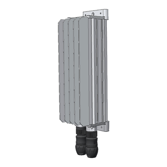
Power Supply Module, 48 VDC, 650W, HE, IP65
Low Power Outdoor Applications
Introduction
Warnings
..................................................................................................................., page 3
Tools & Torque Recommendations
Recommended External AC Fuses
Overview
..................................................................................................................., page 4
Block Diagram Chameleon Stand-alone Power Supply Module ...........................
Dimensions Chameleon Stand-alone Module ..........................................................
Mechanical Installation
Fastening the Chameleon Module to a Surface or Pole
Option 1: Surface Mounting ~ Prepare the Surface ...............................................
Option 1: Surface Mounting ~ Fasten the Chameleon Module ............................
Option 2: Pole Mounting ~ Fasten Half Pole Clamps to the Module ...................
Option 2: Pole Mounting ~ Fasten the Chameleon Module to the Pole .............
Electrical Installation
Location of Terminals & Cable Management
Cable Management ........................................................................................................
Pinout ~ Panel Mount Connectors ...........................................................................
Location of Terminals ~ Cable Connectors ............................................................
Connections ..........................................................................................................
Switch OFF External Fuses ........................................................................................
Connect the AC Input Cable ......................................................................................
Connect the DC Output Cable ..................................................................................
Start-Up
Check Lists ~ Pullout
Commissioning Procedure
....................................................................., page 3
......................................................................, page 3
................................, page 5
..................................................., page 8
356849.103
, page 4
, page 4
, page 5
, page 6
, page 6
, page 7
, page 8
, page 10
, page 10
, page 11
, page 11
, page 12
, page 13
Advertisement
Table of Contents

Related Manuals for Eltek Chameleon Stand-alone


Summary of Contents for Eltek Chameleon Stand-alone
- Page 1 Recommended External AC Fuses .............., page 3 Overview ........................, page 4 , page 4 Block Diagram Chameleon Stand-alone Power Supply Module ......, page 4 Dimensions Chameleon Stand-alone Module ............Mechanical Installation Fastening the Chameleon Module to a Surface or Pole ........, page 5...
-
Page 2: Safety And Environmental Precautions
Always tighten screws and bolts with the torque values recommended in the documentation. For safety reasons, the commissioning and confi guration of the equipment is only to be performed by Eltek’s personnel or by author- Qualifi... -
Page 3: Torque Recommendations
Introduction ••• Warnings WARNING: Hazardous voltages may be present inside the Chameleon module, Part # 241125.155, as long as 10 Electric Shock minutes after it is switched OFF (discharge time) 10 min. WARNING: – If used as PERMANENTLY CONNECTED, a readily accessible disconnect device shall be incorporated external to the equipment –... -
Page 4: Overview
Introduction ••• Overview Block Diagram Chameleon Stand-alone Power Supply Module Chameleon 48V, 650W, HE Stand-alone Module Telecom & Industrial Equipment AC Fuses, external (Load) Alarm Relay C-NO CAN bus AC Input DC Output (230V 1x phase) (48V) Dimensions Chameleon Stand-alone Module... -
Page 5: Mechanical Installation
CAUTION: The wall or support surface or pole must be capable of supporting the equip- ment: 2.8 Kg or 3.6 Kg, ±10%, depending on the Chameleon Stand-alone Module WARNING: Never mount the Chameleon Stand-alone Module in the vicinity of heaters or... -
Page 6: Option 1: Surface Mounting ~ Fasten The Chameleon Module
Mechanical Installation ••• Option 1: Surface Mounting ~ Fasten the Chameleon Module (2x) Suitable acid proof (A4) Screw or Bolt Option 2: Pole Mounting ~ Fasten Half Pole Clamps to the Module M5 (2x) T-PZ2 Pressure Equalization Vent Half Pole Clamp WARNING: Do not open, close or change the Pressure Equalization Vent, which Device... -
Page 7: Option 2: Pole Mounting ~ Fasten The Chameleon Module To The Pole
Both bolts tightening a half pole clamp pair must be screwed almost at the same time and the same length, maintaining the half pole clamps par- alleled while fastening Chameleon Stand-alone Module Chameleon Stand-alone Module (Top View) (Top View) Pole Half Pole Clamp A≠B... -
Page 8: Electrical Installation
Electrical Installation ••• Location of Terminals & Cable Management Power is OFF! Cable Management Insert, male with Coupling Ring Sleeve with Pinch Ring Seal Ring, SR1 Pressing Screw Seal Cable Panel Mount Cable Ring, SR1 Connector, Connector, Connector, Panel Mount Seal female male... -
Page 10: Commissioning Procedure
Software, version No.: AC Input Voltage, measured: Commissioning carried out by, name: Pre-Start Check Power is OFF! CHECK FOLLOWING 1. Chameleon Stand-alone installation is completed; All cabling is securely terminated Device Hazard 2. Site specific parameters are known ... - Page 13 Select the cable connector type that corresponds to your cable outer diameter, ±0.2 mm Cable Connectors Selection Table Cable Type Cable Connector Type Function Outer Diameter Connector Type Eltek’s Part No. Binder’s Part Number Pressing Screw’s Torque Input Cable 12—17 mm Input Connector (SR1) 343665 99-4222-300-04 (3+PE) 1.6 —2.0 Nm...
-
Page 14: Location Of Terminals ~ Cable Connectors
Contacts AL-NO shown with L1/N de-energized coil (Alarm condition) AL-C (not connected) CAN H CAN L Chameleon Stand-alone Module Location of Terminals ~ Cable Connectors Contacts shown with de-energized CAN L coil (Alarm condition) AL-C AC Mains DC Load Input... -
Page 15: Connections
Electrical Installation ••• Connections Power is OFF! Switch OFF External Fuses WARNING: CAUTION: For outdoor applications where the product may be subject Suitable for connection to IT networks to transient overvoltages exceeding those for Overvoltage Current Surge Protection Category II, an AC Overvoltage Protection Device (OVP) complying with IEC 61643-series must be installed on the For installations in USA and Canada only! AC supply. -
Page 16: Connect The Ac Input Cable
Electrical Installation ••• Connect the AC Input Cable AC Mains Cable Cable Connector, female A (Part 343665) Tin wires (3x) AC Mains Cable CAUTION: The rectifier incorporates a Mains fuse in each line. Double Pole / Neutral Fusing L1/N AC Mains Input Terminals Connect AC Mains cable... -
Page 17: Connect The Dc Output Cable
Electrical Installation ••• Connect the DC Output Cable DC Output Cable Cable Connector, male F (Part 343667) Tin wires (7x) DC Output Cable WARNING: — Careful! Use correct polarity! — The DC Load’s wire cross section must be 1.5 mm2 (pin 1 & 2) CAN L —... - Page 18 Electrical Installation ••• Quick Installation Guide • Chameleon 48V, 650W, HE, IP65, Stand-alone Module...
- Page 19 Start-Up ••• Refer to the steps in the pull-out form “Commissioning Procedure” Quick Installation Guide • Chameleon 48V, 650W, HE, IP65, Stand-alone Module...
- Page 20 This product is CE marked and complies with all current requirements for relevant standards and directives. www.eltek.com Headquarters: Eltek Visitor address: Gråterudveien 8, 3036 Drammen, Norway Phone: +47 32 20 32 00 Fax: +47 32 20 32 10...
Need help?
Do you have a question about the Chameleon Stand-alone and is the answer not in the manual?
Questions and answers