Table of Contents
Advertisement
Advertisement
Table of Contents

Related Manuals for Eltek Smartpack


Summary of Contents for Eltek Smartpack
- Page 1 User’s Guide Monitoring and Control Unit Flatpack2 DC Power Supply Systems...
- Page 2 Certificate no: 900005E Safety Precautions The equipment described in this manual must only be operated by Eltek Energy personnel or by persons who have attended a suitable Eltek Energy training course The equipment represents an energy hazard and failure to observe this could cause terminal injury and invalidate our warranty There are hazardous voltages inside the power system.
-
Page 3: Table Of Contents
LCD Display ........................17 Front Keys........................17 Modes of Operation.....................18 Status Mode ........................18 Menu Mode ........................18 Operating Menus, Overview ................18 User Options UO......................19 Service Options SO....................20 Technical Specifications User’s Guide Smartpack Monitoring & Ctrl Unit, 350003.013, v5-2006-11... - Page 4 UO (Mains Info)............. 25 Display Battery Temperature Levels UO (TempLevel Info) ........25 Display Battery Information UO (BatteryInfo)............. 26 About Battery Banks, Strings and Blocks ................26 Battery Symmetry Measurements ⎯ 48V Systems..............27 User’s Guide Smartpack Monitoring & Ctrl Unit, 350003.013, v5-2006-11...
-
Page 5: Welcome
Smartpack-based DC power system. System Diagram ⎯ Flatpack2 Power System In the Flatpack2 PS system shown in Figure 1, the Smartpack controller monitors and controls the whole system, and serves as the local user interface between you and the system. The PowerSuite application is used for remote operation and system configuration. -
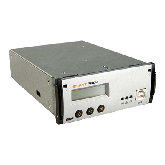
Page 6: The Smartpack Controller
2 The Smartpack Controller 2. The Smartpack Controller The Smartpack controller is a monitoring and control unit used as the vital nerve center of the DC power plant. You operate the system from the elegant front panel, using three front keys and the LCD-display. They represent the main interface between you and the system. -
Page 7: Typical Applications
2 The Smartpack Controller Typical Applications The Smartpack controller employs CAN bus communication with the rectifiers in the Smartpack-based DC power system ⎯ and other bus-connected Smartpack controllers in the system ⎯ thus enabling flexible expansion of system functionality and number of measuring points. -
Page 8: System & Battery Signals ⎯ Internal Connections
2 The Smartpack Controller System & Battery Signals ⎯ Internal Connections In standard Smartpack-based DC power systems, the controller’s internal signals are cabled either directly to the corresponding monitoring or measuring points, or to internal terminals, as shown in Figure 5. See your system’s specific arrangement drawings. -
Page 9: Alarm Relay & Digital Input Signals ⎯ Customer Connections
2 The Smartpack Controller Alarm Relay & Digital Input Signals ⎯ Customer Connections In standard Smartpack-based DC power systems, the controller’s customer alarm relay and digital input signals are cabled to dedicated easy accessible terminals, as shown in Figure 6. See also your system’s specific arrangement drawings. -
Page 10: Can Port Signals ⎯ Internal Connections
CAN bus Addressing Eltek’s CAN bus may address a maximum of 60 nodes. Among them, you may connect a maximum of 8 Smartpack controllers and or 50 rectifiers. Hardware Assignment ⎯ Controllers... -
Page 11: Software Assignment ⎯ Rectifiers
Each rectifier in the Smartpack-based DC power system is automatically configured by the Smartpack controller with a unique CAN bus ID number (software-assignment). When the rectifiers are hot-plugged in the power shelves the first time, the Smartpack controller dynamically assigns the rectifiers with the next available ID number (software- assignment), and automatically increases the number of communicating rectifiers on the CAN bus. -
Page 12: Firmware Upgrade Of The Smartpack Controller
Figure 10 FWLoader dialog box While the firmware is loaded to the Smartpack controller, the FWLoader program displays a progress bar, and the controller’s display shows the currently programmed segment. Once the firmware has loaded, the Smartpack controller will automatically restart. -
Page 13: Module Options
2 The Smartpack Controller Module Options The Smartpack is a scalable controller with modular design. It can be optimized for different requirements by means of plug-in-kits. Various Smartpack controller options are available offering remote control management via modem, Web, e-mail and SNMP. -
Page 14: Smartpack Controller ⎯ Rs232
2 The Smartpack Controller Smartpack Controller ⎯ RS232 The Smartpack controllers – in RS232 option, Art 242100.111 (front access) and Art 242100.112 (rear access) – allow remote system monitoring and control by connecting to the RS232 port either a modem or Eltek’s stand-alone WebPower unit (Ethernet support). -
Page 15: Smartnode Module
Smartnode module Figure 17 The Smartpack controller communicating with the Smartnode module The example in Figure 17 shows schematics of how the Smartpack controller can communicate with external equipment with specific protocols, using the Smartnode as a protocol translator. User’s Guide Smartpack Monitoring & Ctrl Unit,... -
Page 16: Installation Of Smartpack Controller
Mounting and Removing the Controller The Smartpack controller incorporates handles that serve both to lock the module into position and to pull it out of its housing. CAUTION: Do not hand-carry the controller by its handles. Cables are plugged to the controller’s rear panel. -
Page 17: Front Panel Operation
See also chapter “Modes of Operation”, on page 18. Front Keys You can control the whole Smartpack-based DC power system via a network of software menus accessed with the controller’s front keys. Press on the key to change from Status Mode to Menu Mode. -
Page 18: Modes Of Operation
Notice that if no keys are pressed within 30 seconds, the display will automatically switch from Menu Mode and to back to Status Mode. Operating Menus, Overview The Smartpack-based DC power system’s functionality is accessed via a network of software menus and submenus, enabling you to configure and control the whole power system. -
Page 19: User Options Uo
NoOfString Nn BattStringCurr ↓↑ BattStringTemp ↓↑ Battery Info BattBlockVolt ↓↑ For description of the User menu options, read chapter “Functionality Description” page 22. Also, refer to the PowerSuite online Help system. User’s Guide Smartpack Monitoring & Ctrl Unit, 350003.013, v5-2006-11... -
Page 20: Service Options So
↑ RelayTest Alarm Output 2 ↑ Batt Contactor ↑ Load Contactor ↑ Alarm Output nn BattLifeTime Rst For description of the Service menu options, refer to the PowerSuite online Help system. User’s Guide Smartpack Monitoring & Ctrl Unit, 350003.013, v5-2006-11... -
Page 21: Technical Specifications
From an NMS via Ethernet (SNMP) yellow) LED is lit in the front panel, the alarm text appears in the LCD and the corresponding alarm relay With an SNMP agent connected to the Smartpack, the is activated. system can be monitored and controlled from a... -
Page 22: Functionality Description
When Automatic Alarm Reset is enabled (default) ⎯ and the alarm condition no longer exists ⎯ the Smartpack controller will deactivate the alarm lamps and relays to indicate that normal operation is established. When Manual Alarm Reset is enabled ⎯ and the alarm condition no longer exists ⎯ the operator must reset the alarm manually. -
Page 23: Display Controller's Firmware Version Uo (Softwareinfo)
“UserOption>SerialNumber”, via the Smartpack controller’s front keys. The serial numbers are displayed in the format <cc: nnnnnnnnnnnn>. The “cc:” represents the ID or CAN bus address of the Smartpack controller with serial number “nnnnnnnnnnnn”. Press the keys to display the serial numbers of other controllers in the CAN network. -
Page 24: Plug-And-Play Rectifier
6 Functionality Description Plug-and-Play Rectifier When a rectifier is hot plugged in a power shelf for the first time, the Smartpack controller assigns the next available ID number to the rectifier, starting with “01”. This ID number (or CAN bus address) and the rectifier’s serial number are stored in both modules. -
Page 25: Display System Mains Data Uo (Mains Info)
Display System Mains Data UO (Mains Info) You can display information about the power system’s AC feed by selecting “UserOption>Mains Info”, via the Smartpack controller’s front keys. Following data may be displayed selecting the Mains Info sub options (level 3): Option... -
Page 26: Display Battery Information Uo (Batteryinfo)
Low Limit, °C High Limit, °C Hours You can reset the values in the Battery Lifetime Temperature monitor either by selecting “ServiceOption>BattLifeTime Rst”, via the Smartpack controller’s front keys, or using PowerSuite. Display Battery Information UO (BatteryInfo) You can display information about the power system’s battery bank by selecting “UserOption>Battery Info”, via the Smartpack controller’s front keys. -
Page 27: Battery Symmetry Measurements ⎯ 48V Systems
PowerSuite PC program. Double Mid-point Measurement Card, Art. 200576 Symmetry Symmetry Each Smartpack controller is equipped with 8 battery Serial Switches symmetry inputs (on CON4 and CON3), enabling symmetry measurement of: 2 battery strings (block meas. method) 4 battery strings (double mid-point meas. - Page 28 +47 32 20 32 00 +47 32 20 32 10 Americas Eltek Energy, LLC +1 815 459 9100 +1 815 459 9118 Asia/Pacific Eltek Energy Pte Ltd. +65 6 7732326 +65 6 7753602 China Eltek Energy Ltd. +769 22651108 Europe Eltek Energy UK Ltd.
Need help?
Do you have a question about the Smartpack and is the answer not in the manual?
Questions and answers
Após a alteração de um dos módulos Smartpack (módulo retificador) de um retificador Eltek, qual o alarme que será sensibilizado pelo equipamento,