Table of Contents
Advertisement
Quick Start Guide
Installation, Operation, Commissioning and Maintenance
Minipack, PS System
DC Power Supply System
Integrated Applications
356808.103
Introduction
The Smartpack based Product Range
o
Brief System Description ⎯ Minipack
o
Installation
o
o
⎯ Opening or Closing the Minipack Drawer Shelf
⎯ Mounting or Removing Minipack Blind Covers
⎯ Removing or Mounting Load MCBs
⎯ Configuring Priority and Non-Priority Load Circuits (5)
Installation Steps; mechanical, electrical
o
Location Of Components, Ga Drawing; 6 and 4 rectifiers systems
o
o
(10 )
o
o
Operation
Front keys and display
o
Software Menus
(12)
o
Miscellaneous
o
Installing PowerSuite – PC software
o
o
o
Battery Symmetry – Connections
o
Battery Interface Card ~ Terminals & Pin-out,
o
Alarms & Monitoring
Standard Alarm Relays & Digital Inputs
o
Alarm Interface Card ~ Terminals & Pin-out
o
Alarm Interface Card, Extd. ~ Terminals & Pin-out
o
Internal Connections
System Interface Card ~ Terminals & Pin-out
o
o
Drawings
Block Diagram Minipack 48VDC, 3.2kW
o
Block Diagram Minipack 48VDC, 4.8kW
o
Check Lists
o
o
o
o
(2 )
(2 )
( 3)
(4)
(4)
(5)
(6-7)
(9)
(10-11)
(12)
(13)
(13)
(14)
(14)
(15)
( 16)
(17)
(17)
(19)
(19)
(21)
(22)
(8)
(18)
pullout forms
Advertisement
Table of Contents

Related Manuals for Eltek Minipack


Summary of Contents for Eltek Minipack
-
Page 1: Quick Start Guide
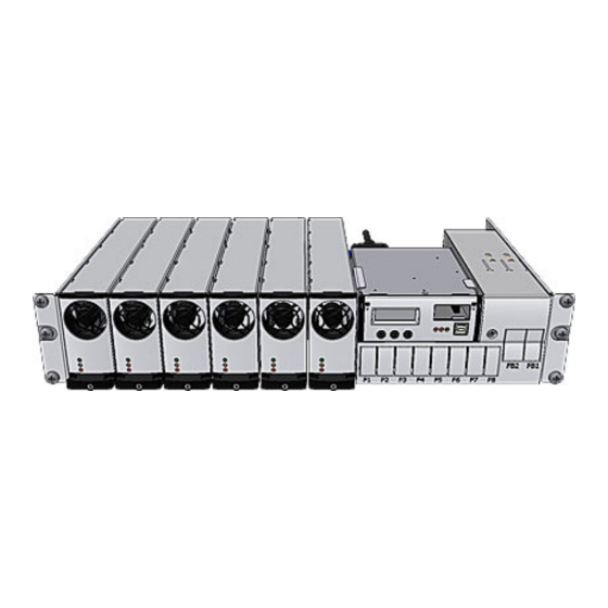
Installing Smartpack and Rectifier Modules ( 3) Installation and Maintenance Details ⎯ Opening or Closing the Minipack Drawer Shelf ⎯ Mounting or Removing Minipack Blind Covers ⎯ Removing or Mounting Load MCBs ⎯ Configuring Priority and Non-Priority Load Circuits (5) Installation steps;... - Page 2 Battery string #1 Example of a typical Minipack PS system for DC power supply of telecom equipment. The system is supplied from an external AC mains supply, and is delivered in one power shelf for integration in existing cabinets (integrated). An external battery bank is to be connected.
- Page 3 Do not relocate already hot-plugged rectifiers to other positions in the power shelf. New rectifiers must be hot-plugged in the power shelf, one at time, starting from the left with position 1, 3, 5 and 2, 4, 6. Mounting or Removing Minipack Rectifier Modules Minipack 1. Unlock the module by...
- Page 4 Installation Details Installation and Maintenance Details Opening or Closing the Minipack Drawer Shelf To access the Minipack distribution area, you have to open the Fastening screws sliding drawer shelf. Do following to open or close the drawer: for the drawer...
- Page 5 Plugs for MCB1 WARNING: Only one screw can be removed at a time. P=Priority Load Circuits NP =Non Priority Load Circuits F3-F10 Screw (Y6) F5-F10 Screw (Y7) F7-F10 Screw (Y24) F9-F10 Screw (Y25) Quick Start Guide Minipack PS System 356808.103, v1-2006-12...
-
Page 6: Installation Steps
Connection terminals are accesses by opening the drawer shelf o Battery shelves (if any) are placed behind the lower panels Position and fasten the subassembly o Minipack is fastened in existing 19” or in ETSI cabinets, using brackets Mount the external batteries on the shelves... - Page 7 (Fb1, Fbx) and the AC supply fuses, in external fuse boards 10 AC Connections Minipack drawer shelf slid out in o Check AC configuration: the external AC supply consists of 3 the maintenance position single phase mains feed and earth (PE) o Connect the AC Earth wires (PE) to the terminals X5:1-2 (PE) o Connect the AC input cables to the terminals X5:3-4, 5-6, 7-8.
- Page 8 Installation Location of Components, GA drawing Refer to the specific drawings included with your Minipack PS system, for information regarding the exact location of components in your system. CAN1 Plastic Protective Cover for CAN bus communication with rectifiers (to Smartpack rear)
- Page 9 Alarm Outputs & Digital Inputs Extended (X2A & X2B) Terminal Circuit Board, Art. 218473 Digital Input 3-6 and Relay Output 3-6 (Not applicable for Smartpack Ethernet option) (See page 18 for pin-out information) Quick Start Guide Minipack PS System 356808.103, v1-2006-12...
- Page 10 After the ”Pre-start Check” is performed, you can begin with stage II. During the stage, you will switch ON the Minipack PSS — while the batteries and load are disconnected ⎯ then measure the output voltage, and adjust it if required. Carry out the following:...
- Page 11 6. Connect the a PC to the PS system (to facilitate operation) o Plug a standard USB A-B cable between the PC and the Smartpack controller o Start PowerSuite on the PC by selecting: Start > All Programs > Eltek > PowerSuite Refer to chapter “...
- Page 12 Smartpack control unit LED Lamp (yellow) Smartpack Control Unit — front keys, display, etc Minipack Rectifier Module — front panel Power LED is OFF (mains unavailable), Flashing Display: is in Status Mode (displays the system’s (controller accessing information) or ON (powered).
- Page 21 4. Start PowerSuite and establish connection Select “Start > All Programs > Eltek > PowerSuite”. On the toolbar, click “Connect” button. On the Connection dialogue box, click the “Connect” button If PowerSuite fails communicating via the standard COM port, find the COMx assigned to Smartpack, by selecting menu option “Tools >...
- Page 22 ID number to the rectifier, starting with “01”. When a previously installed (hot plugged) Minipack rectifier is inserted in a power shelf, the Smartpack controller “recognizes” the module, and assigns the same ID to the rectifier. In other words, the controller and the rectifier “remember”...
-
Page 23: Battery Monitoring
Battery Block, Battery String and Battery Bank Battery Block (12V) Battery String #1 (48V)Batt. — (-48V) Outer Terminal Block1 Block3 Block4 Battery String #2 Intercell Links 48V Battery Bank 0V Outer (48V) Terminal Quick Start Guide Minipack PS System 356808.103, v1-2006-12... - Page 24 (Alternative use of Temp. Sense Kit, instead of connecting to X3: 9-10) Temperature sensor The Temperature Sense Kits may also be connected directly to the Smartpack controller’s CON3 or CON4, if these connectors are unused. Quick Start Guide Minipack PS System 356808.103, v1-2006-12...
- Page 25 Alarms & Monitoring Standard Alarm Relays & Digital Inputs Connections Standard Relays & Digital Inputs Normal Mode The alarm outputs in Minipack systems use the Fail-Safe Relay X (Energized coil) Operation Mode (relay coils energized in the system’s — normal operation mode). When the system is in alarm...
- Page 26 Alarm Circuit 3 Relay 4 Alarm Circuit 4 High Battery Alarm Relay 5 Alarm Circuit 5 Low Battery Alarm Relay 6 Alarm Circuit 6 Rectifier Alarm (Customer Connections) 1.5 mm , max. wire section Quick Start Guide Minipack PS System 356808.103, v1-2006-12...
- Page 27 CON5, on the controller’s rear panel. Using a standard 15 pins D-Sub cable, the signals on CON5 are routed to the Minipack system’s main circuit board. See the figure in this section for an overview of the signals on CON5,...
- Page 28 Quick Start Guide Minipack PS System 356808.103, v1-2006-12...
- Page 31 Quick Start Guide Minipack PS System 356808.103, v1-2006-12...
- Page 32 Head Office Eltek Energy AS Copyright © Eltek Energy AS, Norway 2005 PO Box 2340 Strømsø; N-3003 Drammen; Norway This document may be changed without notice Tel:+47 32 20 32 00 — Fax:+47 32 20 32 10 Art.
Need help?
Do you have a question about the Minipack and is the answer not in the manual?
Questions and answers