
Related Manuals for Ultimate Healthcare Cura II


Summary of Contents for Ultimate Healthcare Cura II
- Page 1 Cura II & Cura II Supreme Community bed frames User Manual Issue 6: 08/11/2018 DRAFT UBEB7002.UBEB7002S.UM-6...
-
Page 2: Table Of Contents
Contents Introduction .......................... 4 Intended Use ........................5 Product Description ......................6 Model variations ....................... 6 Symbols and Statements ..................... 7 Safe Use Guidelines ......................8 5.1 Safety information – nursing personnel, carers and users ........... 8 Safety information – bed assembly ................9 Safety information –... - Page 3 13.4 Attaching telescopic full length side rails to the bed ..........26 13.5 Lifting poles ......................27 13.6 Side rail bumpers ....................27 13.7 Mattress squab ...................... 27 13.8 Mesh full length side rail bumpers ................. 27 13.9 Attaching mesh full length rail bumper extension ..........27 Transport and Storage .......................
-
Page 4: Introduction
Note: Ultimate Healthcare reserves the right to modify the information in this User Manual at any time. The information in this User Manual may vary slightly with respect to the basic design of the product. -
Page 5: Intended Use
2. Intended Use The bed is intended to support patients using the moveable sections as and if required within the following environments; Nursing home Home This bed must not be used for any other purpose than that which it is intended, for example it must not be used as a standing platform. -
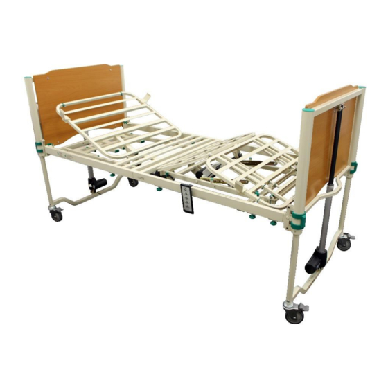
Page 6: Product Description
Maximum user weight 215kg (34 stone) – Safe working load 250kg (39.5 Stone) Accessories – please see Accessories Section 13 in this Manual. Model variations Cura II Cura II Supreme (10-button handset) (10-button handset) Bed raise/lower function Bed raise/lower function... -
Page 7: Symbols And Statements
Symbols used in this manual and on the Cura II and Cura II Supreme community bed: B symbol, indicates this product is according to degree of protection against electric shock for type B equipment. -
Page 8: Safe Use Guidelines
If you have any questions, please contact Ultimate Healthcare (see details on the back cover). Warning: Danger to life and risk of injury due to trapping/pinching/damage! ... -
Page 9: Safety Information - Bed Assembly
Warning: Possible danger to life due to alteration of the patient’s position Always lock (disable) all handset adjustment functions which could cause danger to the patient’s health if adjusted (consult doctor). Always take account of the patient’s condition when locking (disabling) the adjustment options. -
Page 10: Safety Information - Maintenance And Inspection
Immediately remove faulty/defective beds from operation and secure them against unauthorised use. Disconnect the mains plug from the wall socket. Only use original spare parts from Ultimate Healthcare. Always carry out the prescribed maintenance and inspection work at the specified intervals, see Section 16 Maintenance and Inspection. -
Page 11: Environmental Conditions
Altitude range (above mean sea level) 3,000m The IP (liquid and dust ingress) rating for the control module on the Cura II and Cura II Supreme medical beds is IPX6. The Cura II and Cura II Supreme beds are designed for medical purposes only. -
Page 12: Installation And Set-Up
7. Installation and Set-Up Assembling the bed Remove packaging; all cardboard is recyclable; carefully dispose of all plastic packaging to avoid risk of suffocation; recycle plastics where facilities exist. Caution: Read these instructions carefully before attempting to assemble the bed. 1. - Page 13 Figure 4: Foot section attachment Figure 5: Collar locked Figure 6: Head section actuator to bed end Whether choosing the lower or high brackets ensure the bed platform is clipped into the same level of bracket on all four legs. 10.
- Page 14 If when operating the handset the functions operate incorrectly it may be that the cables are located in the wrong actuators. The bed will have to be carefully turned over again and the cables will have to be inserted into the correct actuator points. The bed will then have to be carefully put back onto its wheels and tested again to make sure the handset operates the correct parts of the bedframe.
-
Page 15: Before Using The Bed
Before using the bed 1. Check all locking collars are locked, i.e. the label is covered. 2. Ensure all securing straps are released. Secured tags Released secure tags 3. Check all thumb wheels are tight. 4. Are all cables correctly routed and have sufficient slack to allow for movement of the bed? 5. -
Page 16: Handset Control
8. Handset Control Handset Controls are supplied with 10 buttons. Caution: Ensure that no person, limbs or objects in any way interfere with the desired movement of the bed. 10-button handset Functions on LED Backrest Knee-break Back and knee-break Height Adjustment Trendelenburg Functions can be locked to prevent them being used by the patient. -
Page 17: Bed Adjustments
9. Bed Adjustments Knee-break section adjustment To raise the knee-break section of the bed, press and hold the Up Knee-Break Adjustment Button on the handset to reach the desired position. To lower the knee-break section of the bed, press and hold the Down Knee-Break Adjustment Button on the handset to reach the desired position. -
Page 18: Backrest Section Adjustment
Backrest section adjustment To raise the head section press and hold the Up Backrest Adjustment Button on the handset until it reaches the desired height. To lower press and hold the Down Backrest Adjustment Button on the handset. Bed height adjustment To raise the height of the bed press and hold the Up Height Adjustment Button on the handset until it reaches the desired height. -
Page 19: Trendelenburg And Reverse Trendelenburg
Trendelenburg and Reverse Trendelenburg To tilt the mattress platform into the head down tilt (Trendelenburg) press and hold the Trendelenburg Adjustment Button. To tilt the mattress platform into the foot down tilt (Reverse Trendelenburg) press and hold the Reverse Trendelenburg Adjustment Button. Use of the Trendelenburg or Reverse Trendelenburg function may require the castor brakes to be taken off one end of the bed as this function slightly changes the footprint of the bed. -
Page 20: Selecting A Mattress
11 Selecting a Mattress Ensure the selection of an appropriate mattress depending on whether the bed is set to standard or extended mode. Having placed the mattress on the bed a risk assessment should be performed to identify potential entrapment risks for the user. Warning: if using side rails, the distance from the top of the uncompressed mattress to the top of the side rail should be more than 220mm. - Page 21 ‘Twist and lock’ locking pin ‘Twist and lock’ locking pin on support extension on platform extension Showing extended bed Turning screw (on both sides) frame Figure 17: Extending the bed frame Figure 18: Extending the platform Caution: Ensure that the mattress platform has been fully extended to bed end before use.
-
Page 22: Accessories
Accessories There are a number of accessories available for the bed provided by Ultimate Healthcare and have been tested with this bed. Please refer to the User Manual for the accessory before using it with the bed. Below is a list of the accessories available for the bed. -
Page 23: In Line Grab Rail
When attaching side rails the consideration of safety is paramount. Side rails that have been manufactured by Ultimate Healthcare carrying the product codes UBEB7002-2 have been specifically designed for the Cura range of beds; however you must ensure the following points are adhered to: 1. -
Page 24: Daily Checks On Side Rails
This User Guide is for the installation of UBEB7002FL-2, the full length extending side rails; these side rails have been specifically designed for the Cura II Bed and should not be attached to any other bed. The full length side rails are supplied in pairs. -
Page 25: Operating The Full Length Side Rails
10. Undo and remove the hand screw at the bottom of each fixing channel Hand screw 11. The next section is easier if you extend the bed platform slightly, follow the instructions in section 12 earlier in this manual. 12. Ensure the end of fixing wire is secured into the hole shown on the image below Fixing wire Hole to insert fixing wire 13. -
Page 26: Attaching Telescopic Full Length Side Rails To The Bed
This User Guide is for the installation of the full length extending side rails; these side rails have been specifically designed for the Cura II, Cura II Supreme and Cura Community Bed and should not be attached to any other bed. The full length side rails are supplied in pairs. The bed side rails can be secured when the bed is extended or unextended. -
Page 27: Lifting Poles
13.5 Patient Lifting Pole 1. Insert base section into locating hole at the head end of the bed. 2. Insert the top section of the pole and attach the handle 13.6 Side Rail Bumpers 1. Wrap the side rail bumper UBEB002001 over the side rail and secure the velcro at the bottom of the side rail. - Page 28 The mesh side rail bumpers have been specifically designed for the Cura Community, Cura II and Cura II Supreme beds. 1. Remove bed rail bumpers from the packaging and dispose of the packaging safely.
-
Page 29: Transport And Storage
14. Transport and Storage 14.1 Disconnecting the controller 1. Ensure castor brakes are engaged – these are foot operated only. 2. Ensure the mains lead is disconnected before starting to dismantle the bed for transport or storage. 3. Remove the mattress. 4. -
Page 30: Storing The Bed
14.3 Storing the bed When not in use this bed must be stored in a dry, clean environment. We recommend that storage temperatures are between -5 C and that % Relative Humidity (RH) is between 10~60%. 15. Cleaning and Disinfection Disconnect the bed from the electricity supply before carrying out decontamination procedures 15.1 Cleaning... -
Page 31: Maintenance And Inspection
Maintenance and Inspection Hazards due to electrical and mechanical faults! Immediately remove faulty/defective medical beds from operation and secure them against unauthorised use (disconnect the mains plug). Immediately show any defects to the responsible personnel. It is imperative that you always rectify any faults which could influence the function and safety of the nursing bed immediately. -
Page 32: Trouble Shooting
The table below has been created to assist with resolving faults you may come across; if the instructions here do not resolve the issue or the issue you are experiencing is not listed please contact your supplier or Ultimate Healthcare using the details found on the back cover of this manual. -
Page 33: Reuse
Reuse The Ultimate Healthcare beds are designed for reuse. They must be cleaned and disinfected prior to reuse as per Section 15. Disposal Beds consist of: Metal parts Plastic parts Electronic components Electric cables Rechargeable batteries/batteries Disposal of the individual materials must be carried out in accordance with the valid regional environmental and disposal regulations. -
Page 34: Expected Service Life
Expected Service Life The expected service life of any medical bed is highly dependent on usage, storage conditions and maintenance regime. Providing that usage is not excessive, that the bed is used and stored in ideal conditions and that the routine maintenance is strictly followed, that any damage is repaired immediately then this bed is expected to have a service life in excess of 5 years. -
Page 35: Electrical Data
21.2 Electrical data Do not dispose of in household waste Voltage type - alternating Insulation Class II, Type B The patient is not separated from the Ground and the chassis For indoor use only 100V - 240V Voltage supply 50/60Hz Voltage input frequency 2.5A (control pack) Current drawn by device... -
Page 36: Warranty
Warranty Ultimate Healthcare is committed to selling high-quality products. However for one reason or another there may be a time when you need to exchange or repair a product. Please make sure you check all items carefully on receipt and follow the manufacturer guidelines. It is recommended you keep a receipt or order number to ensure any warranty claim is handled efficiently. -
Page 37: How To Make A Claim
d. any loss suffered as a result of not being able to use the Product, or any loss other than the repair or the replacement cost of the Product. Before agreeing to replace or repair your Product under this Warranty the Company reserves the right to require that it is returned to the Company. - Page 38 Issue: 6: 08/11/2018 Page 38 of 40 DRAFT...
- Page 39 Issue: 6: 08/11/2018 Page 39 of 40 DRAFT...
- Page 40 Ultimate Healthcare Ltd Calmore Industrial Estate, Nutwood Way, Totton Southampton, Hampshire, SO40 3WW Tel: 0333 321 8996 Email: info@ultimatehealthcare.co.uk www.ultimatehealthcare.co.uk Issue: 6: 08/11/2018 Page 40 of 40 DRAFT...
Need help?
Do you have a question about the Cura II and is the answer not in the manual?
Questions and answers