
Related Manuals for Flowserve D30


Summary of Contents for Flowserve D30
- Page 1 USER INSTRUCTIONS Installation D30 Compact Digital Positioner Operation FCD PMENIM0030-01-A5 – 05/18 Maintenance...
-
Page 2: Table Of Contents
D30 Digital Positioner FCD PMENIM0030-01-A5 – 05/18 Contents 1. Introduction 2. Storage 3. Installation 4. Control 5. Maintenance/service 6. Trouble shooting 7. Technical data 8. Dimensions 9. Spare parts... -
Page 3: Introduction
• Two proximity switches • Two inductive sensors The D30 can be equipped with modules for page 12 for more options available limit switches and pressure gauges. Pressure sensors can be installed to offer advanced diagnostics. - Page 4 IIC explosive atmosphere. The cable connection of the Remote Unit with the D30 – unit shall be type A or B in accordance with EN 60079-25. The cable must be adequately mechanically protected in all instances and have a temperature rating for the ambient temperature range at the site.
- Page 5 When upgrading electronically parts inside a PMV positioner approved for installation in Hazardous locations special procedures apply, permission from PMV/Flowserve is required prior to the start of work. Please contact a Flowserve office for information regarding proper procedures www.pmv.nu or infopmv@flowserve.com -Always turn off the air and electrical supplies before starting any work.
-
Page 6: Storage
The red shipping plugs are not intended as a permanent outdoor plug. The unit should be The D30 positioner is a precision instrument. packed with a desiccant (silica gel) in a plastic Therefore it is essential that it is handled and bag or similar, covered with plastic, and not stored in the correct way. -
Page 7: Installation
Now connect the air supply to the contamination to be blown out. Direct the air filter, which is connected to the D30 positioner. jet into a large paper bag to trap any water, oil, or other foreign materials. If this indicates that the air system is contaminated, it should be properly cleaned before continuing. - Page 8 0,354 0,394 0,091 2,30 All versions of the D30 positioner have an ISO F05 footprint. The holes are used to attach the M8x1 0,189 D30 to the mounting bracket B. Please contact 4,80...
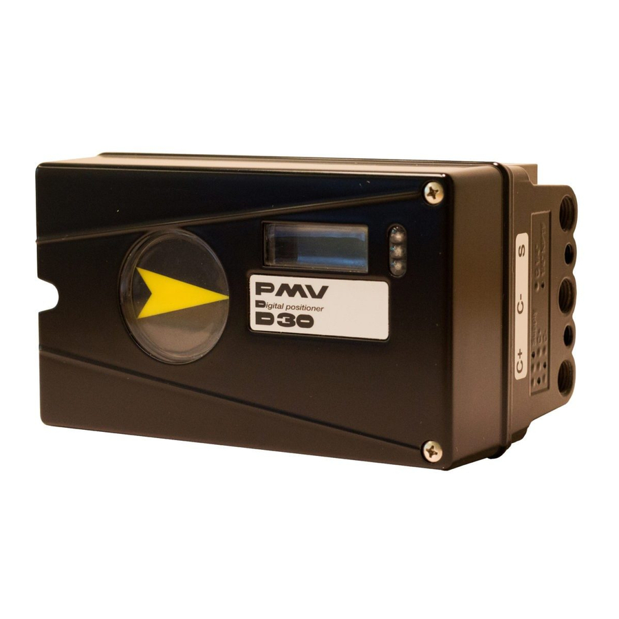
- Page 9 D30 Digital Positioner FCD PMENIM0030-01-A5 – 05/18 Connections Dimensions Air connections: ¼” NPT alt. G ¼” Air: Port S Supply air, 1.4-8 barg (20-115 psi) Electrical connection: M20 x 1.5 alt. NPT ½” Port C+ Connection to actuator, opening Port C-...
- Page 10 D30 Digital Positioner FCD PMENIM0030-01-A5 – 05/18 Single acting positioner, Direct function Actuator with closing spring When the control signal increases, the pressure C+ to the actuator is increased. The valve stem moves upward and rotates the positioner spindle counter- clockwise.
- Page 11 D30 Digital Positioner FCD PMENIM0030-01-A5 – 05/18 Gauge block Gauge blocks are available for D30s with ¼” G or ¼” NPT air connections. To install, ensure seals are aligned, then use 3 Nm (2.2 lb ft) of torque when fastening the gauge block to the positioner using the two screws supplied with the kit.
- Page 12 Optional board INPUT 4-20mA switches or remote SIGNAL The D30 digital positioner has been designed to Option In the event of a severe electrostatic discharge operate correctly in electromagnetic (EM) fields near the positioner, the device should be found in typical industrial environments. Care...
- Page 13 D30 Digital Positioner FCD PMENIM0030-01-A5 – 05/18 Limit switch calibration • Losen screws (1) and adjust cams. • Adjust lower cam first and then upper cam • Tighten screws (1) Aproximat switc DESCRIPTION DESCRIPTION DESCRIPTION DESCRIPTION MATERIAL MATERIAL MATERIAL MATERIAL...
- Page 14 D30 Digital Positioner FCD PMENIM0030-01-A5 – 05/18 Feedback option (cont.) Calibration of the 4-20 mA transmitter Connecting the switches/sensors model code position K model code position B D30 series terminal configuration Min. ATEX IECEx Note SWITCH Type Ci nF Li uH...
- Page 15 D30 Digital Positioner FCD PMENIM0030-01-A5 – 05/18 Type sign example REVISIONS REV. DESCRIPTION DATE APPROVED Area for markings, Ex ratings and associated warnings if applicable Logo type Type and model Input Pressure: Input Signal: Temp Range: Applicable Certificat Special note...
- Page 16 D30 Digital Positioner FCD PMENIM0030-01-A5 – 05/18 D30 Digital Positioner model code Model no D 3 0 Full LCD menu, LED status Approval, Certificate General purpose version ATEX Function High Flow - Single/double acting - Spool valve Connections Air, Electrical 1/4”...
-
Page 17: Control
D30 Digital Positioner FCD PMENIM0030-01-A5 – 05/18 4. Control Menus and pushbuttons BASIC MENU OUT OF SERVICE The positioner is controlled using the five MANUAL pushbuttons and the display, which are MAN/AUTO accessible when the aluminum cover is removed. UNPROTECTED For normal functioning, the display shows the current value. - Page 18 D30 Digital Positioner FCD PMENIM0030-01-A5 – 05/18 Menu indicator FULL MENU There are indicators at both sides of the display window and they indicate as follows: MAN/AUTO Flashing in position Out of service FULL MENU Flashing in position Manual CALIBRATE...
- Page 19 D30 Digital Positioner FCD PMENIM0030-01-A5 – 05/18 Menu system FULL MENU READ BASIC MENU READ FULL MENU MAN/AUTO BASIC MENU MAN/AUTO FULL MENU CALIBRATE BASIC MENU CALIBRATE FULL MENU SHIFT MENU BASIC MENU SHIFT MENU FULL MENU STATUS The menus are described on the following pages.
- Page 20 Expert cal - pot Menu. The calibration sequence must be restarted after the fault is corrected. Tip! Instant quick calibration The D30 can be instantly calibrated by pressing the top + bottom buttons for 5 seconds (see picture). This function is available from any menu position.
- Page 21 The SP has 5 bytes, 4 bytes for the float value 4+1=5 and one status byte. The status byte needs to be 128 (0x80Hex) or higher for the D30 to accept it. READBACK Position The READBACK has 5 bytes, 4 bytes for the 4+1=5 float value and one status byte.
- Page 22 Fieldbus Protocol such as MANUFAC_ID which informs the unique manufacturer id. For Example Flowserve it is 0x464C53. The RB has to be in A typical FF block loop control might look AUTO for the AO-block to be in AUTO.
- Page 23 D30 Digital Positioner FCD PMENIM0030-01-A5 – 05/18 BASIC MENU CALIBRATE The contents of the menu are shown on the next page. The various menu texts are described below. Auto-Cal Auto-tuning and calibration of end positions Start tune Starts the tuning. Questions/commands are displayed during calibration.
- Page 24 D30 Digital Positioner FCD PMENIM0030-01-A5 – 05/18 The menu contents are shown in the figures on the right and the texts are described below: BASIC MENU READ Current values can be read using the Read Menu and some values can be reset.
- Page 25 D30 Digital Positioner FCD PMENIM0030-01-A5 – 05/18 BASIC MENU MAN/AUTO The Man/Auto menu is used to change between manual and automatic modes. The menu contents are shown in the figures on the right and the various texts are described below:...
- Page 26 D30 Digital Positioner FCD PMENIM0030-01-A5 – 05/18 BASIC MENU SHIFT MENU The Shift Menu is used to choose between the basic menu and the full menu. The menu contents are shown in the figures on the right and the various texts are described...
- Page 27 D30 Digital Positioner FCD PMENIM0030-01-A5 – 05/18 FULL MENU SETUP The Setup Menu is used for various settings. The menu contents are shown in the chart on the next page and the various texts are described below: Actuator Type of actuator...
- Page 28 D30 Digital Positioner FCD PMENIM0030-01-A5 – 05/18 TRVL range Setting end positions Start menu Start in Basic menu or 0%=0.0% Select Out of Service. Full menu. Set percentage value for Orient Orientation of text on display. desired end position Par mode Display of control parameters (e.g.
- Page 29 D30 Digital Positioner FCD PMENIM0030-01-A5 – 05/18 FULL MENU TUNING The menu contents are shown in the chart on the next page and the various texts are described below: Close time Minimum time from fully open to closed. Open time Minimum time from closed to fully open.
- Page 30 D30 Digital Positioner FCD PMENIM0030-01-A5 – 05/18 FULL MENU ALARMS The menu contents are shown in the chart on the next page and the various texts are described below: Deviation Alarm generated when deviation occurs On/Off Alarm on/off. Distance Allowed distance before alarm is generated.
- Page 31 D30 Digital Positioner FCD PMENIM0030-01-A5 – 05/18 Temp Alarm based on temperature On/Off Temperature alarm on/off. Low temp Temperature setting. High temp Temperature setting. Hysteresis Allowed hysteresis. Alarm out Select ON/OFF offers output on terminals. Valve act Behavior of valve when alarm is generated.
- Page 32 Pressure LO: Use a supply of 1.4 bar (20 psi) Also see video on www.pmv.nu (or set another value on the display). Press OK. Pressure read out only possible on D30 Full reset: Resets all set values and enters with built in pressure sensor.
- Page 33 D30 Digital Positioner FCD PMENIM0030-01-A5 – 05/18 Replacement for page xx in the D30 IOM for software version 1.2 READ set&pos MAN/AUTO AUT,OK=MAN MAN,OK=AUT set&dev G Highest Pos Graph CALIBRATE AutoCal Supply Pr** n cycles TravelCal C+ & C-** acc travel...
-
Page 34: Maintenance/Service
DO NOT take the valve block apart because its function will be impaired. When working with the D30 positioner, the work place must be equipped with ESD protection before the work is started. Always turn off the air and electrical supplies before starting any work. - Page 35 D30 Digital Positioner FCD PMENIM0030-01-A5 – 05/18 Circuit boards (PCB) Disconnect or switch off the electric power supply before starting any work. • Lift off the display PCB.. • Release the cable connections. • Unscrew the two screws B and lift up the circuit board.
- Page 36 D30 Digital Positioner FCD PMENIM0030-01-A5 – 05/18 Limit Switches When installing the switch card, make sure it is Note! When installing the cam assembly for placed correctly.Secure the PC board with the mechanical switches, retract both switch arms two screws. Make sure the holes are centred first.
- Page 37 D30 Digital Positioner FCD PMENIM0030-01-A5 – 05/18 Valve block Turn off the air and electric power supply before starting any work. • Remove the three screws A and lift out the valve block N.B. Do not disassemble the valve block •...
- Page 38 D30 Digital Positioner FCD PMENIM0030-01-A5 – 05/18 Potentiometer • Turn the spindle shaft clockwise to end position and press OK. Either turn manually 90° spring loaded potentiometer or use the up/down arrows (with supply The spring-loaded potentiometer can be air) to stroke the positioner to turn the shaft...
-
Page 39: Trouble Shooting
D30 Digital Positioner FCD PMENIM0030-01-A5 – 05/18 6. Trouble shooting Symptom Action Input signal change to positioner does not • Check air supply pressure, air cleanliness, affect actuator position. and connection between positioner and actuator. • Out of service, in manual mode. -
Page 40: Technical Data
D30 Digital Positioner FCD PMENIM0030-01-A5 – 05/18 7. Technical data Rotation angle min 25° max 100° Stroke From 5 mm (0.2¨) Input signal 4-20 mA DC Air supply 1.4-8 barg (20-115 psi) DIN/ISO 8573-1 3.2.3 Free from oil, water and moisture. - Page 41 D30 Digital Positioner FCD PMENIM0030-01-A5 – 05/18 Mechanical switches Type SPDT Size Rating 3 A/125 VAC / 2 A/30 VDC Temperature range -40°C to 80°C (–22°F to 180°F) NAMUR sensors (NJ2-V3-N) Type Proximity DIN EN 60947-5-6:2000 Load current 1 mA ≤ I ≤ 3 mA...
-
Page 42: Dimensions
D30 Digital Positioner FCD PMENIM0030-01-A5 – 05/18 8. Dimensions his document must not be copied without our written permission and the contents there of must not be mparted to a third party nor be used for any unauthorized purpose. Contravention will be prosecuted... -
Page 43: Spare Parts
D30 Digital Positioner FCD PMENIM0030-01-A5 – 05/18 9. Spare parts Part no Description D4-SP37PVA Black cover incl. screws and flat indicator D4-SP37FWA White cover incl. screws and flat indicator D4-SP40 Internal cover incl. screws D4-SP1516 External covers SST, 2, incl screws... - Page 44 D30 Digital Positioner FCD PMENIM0030-01-A5 – 05/18...
- Page 46 Flowserve Corporation has established industry leadership in the design and manufacture of its products. When Phone: +86-512-6288-1688 properly selected, this Flowserve product is designed to perform its intended function safely during its useful life. Fax: +86-512-6288-8737 However, the purchaser or user of Flowserve products should be aware that Flowserve products might be used in numerous applications under a wide variety of industrial service conditions.
Need help?
Do you have a question about the D30 and is the answer not in the manual?
Questions and answers