Flowserve D30 User Instructions
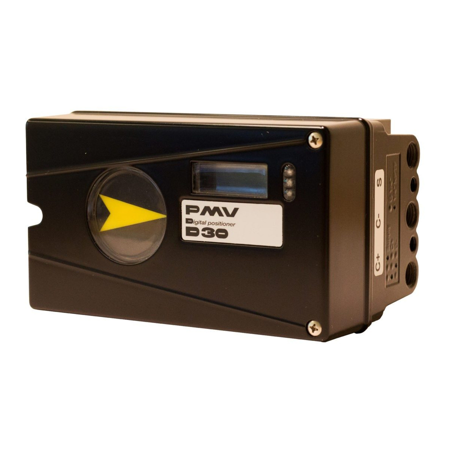
Compact digital positioner
Hide thumbs
Also See for D30:
- Installation, operation & maintenance manual (46 pages) ,
- User instructions (61 pages)

Related Manuals for Flowserve D30


Summary of Contents for Flowserve D30
- Page 1 USER INSTRUCTIONS ® D30 Compact Digital Positioner Installation Operation FCD PMENIM0030-05-A5 - 12/15 Maintenance...
-
Page 2: Table Of Contents
Double action positioner, Direct function .................... Mounting the positioner on ¼ turn actuators ..................Gauge block............................Electrical connections ......................... Type signs ............................D30 Digital Positioner model code ..................... 4. Control ............................... Menus and pushbuttons ........................Other functions ........................... Menu indicator ........................... -
Page 3: Introduction
• Two proximity switches • Two inductive sensors The D30 can be equipped with modules for See page 12 for more options available feedback, limit switches and pressure gauges. Pressure sensors can be installed to offer advanced diagnostics. -
Page 4: Storage
General This is also applicable for long-term storage (more than 1 month) and for long transport The D30 positioner is a precision instrument. by sea. Therefore it is essential that it is handled and stored in the correct way. Always follow the... -
Page 5: Installation
D30 Digital Positioner FCD PMENIM0030-00-A5 12/15 3. Installation Tubing Removal of cover It is recommended to use tubes with a mini- General purpose / Intrinsically safe mum inner diameter of Ø 6 mm (¼”). Remove cover by first loosening the screw 1 and then the two screws 2. -
Page 6: Mounting
Note: If the positioner is installed in a hazardous environment, it must be of a type approved for this purpose. All versions of the D30 positioner have an ISO F05 footprint. The holes are used to attach the D30 to the mounting bracket B. Please contact... -
Page 7: Connections
D30 Digital Positioner FCD PMENIM0030-00-A5 12/15 Connections Air: Port S Supply air, 1.4-8 bar (20-115 psi) Port C+ Connection to actuator, opening Port C- Connection to actuator, closing (only for double action) Plug for single action, see below Electrical connection Must be plugged when converting to See page 10. -
Page 8: Single Action Positioner, Direct Function And Reverse Function
D30 Digital Positioner FCD PMENIM0030-00-A5 12/15 Single acting positioner, Direct function Actuator with closing spring When the control signal increases, the pres- sure C+ to the actuator is increased. The valve stem moves upward and rotates the positioner spindle counter-clockwise. When the control signal drops to zero, C+ is vented and the valve closes. -
Page 9: Mounting The Positioner On ¼ Turn Actuators
Now connect the air supply to the filter, which is connected to the D30 positioner. Gauge block Gauge blocks are available for D30s with ¼” G or ¼” NPT air connections. To install, ensure seals are aligned, then use 3 Nm (2.2 lb ft) of torque when fastening the... -
Page 10: Electrical Connections
The D30 digital positioner has been designed to operate correctly in electromagnetic (EM) An electromagnetic line filter can be used to fields found in typical industrial environments. -
Page 11: Type Signs
D30 Digital Positioner FCD PMENIM0030-00-A5 12/15 Type sign example Type and model Area for logo type Area for switch type and terminals... -
Page 12: D30 Digital Positioner Model Code
D30 Digital Positioner FCD PMENIM0030-00-A5 12/15 D30 Digital Positioner model code Model No. D 30 Full LCD menu, LED status Approvals / Certificate General purpose version Air relay High Flow Spool Valve Connections Threads ¼¨ G air, M20 x 1,5 electrical ¼¨... -
Page 13: Control
D30 Digital Positioner FCD PMENIM0030-00-A5 12/15 4. Control Menus and pushbuttons The positioner is controlled using the five BASIC MENU pushbuttons and the display, which are acces- OUT OF SERVICE MANUAL sible when the aluminum cover is removed. MAN/AUTO For normal functioning, the display shows the current value. -
Page 14: Menu Indicator
D30 Digital Positioner FCD PMENIM0030-00-A5 12/15 Menu indicator There are indicators at both sides of FULL MENU the display window and they indicate as MAN/AUTO follows: Flashing in position Out of service FULL MENU Flashing in position Manual CALIBRATE Displayed in position Unprotected... -
Page 15: Menu System, Basic Vs Full
D30 Digital Positioner FCD PMENIM0030-00-A5 12/15 Menu system BASIC MENU FULL MENU READ READ BASIC MENU FULL MENU MAN/AUTO MAN/AUTO BASIC MENU FULL MENU CALIBRATE CALIBRATE BASIC MENU FULL MENU SHIFT MENU SHIFT MENU FULL MENU STATUS FULL MENU SETUP... -
Page 16: First Start (With Calibration Sequence) Incl. Profibus And Fieldbus
- pot Menu. The calibration sequence must be restarted after the fault is corrected. Tip! Instant quick calibration The D30 can be instantly calibrated by pres- sing the top + bottom buttons for 5 seconds (see picture). This function is available from Instant quick calibration any menu position. - Page 17 The SP has 5 bytes, 4 bytes for the float value 4+1=5 and one status byte. The status byte needs to be 128 (0x80Hex) or higher for the D30 to accept it. READBACK Position The READBACK has 5 bytes, 4 bytes for the 4+1=5 float value and one status byte.
- Page 18 Fieldbus Protocol such as to MODE->Permitted parameter, and then MANUFAC_ID which informs the unique choose MODE->Target to Man. Make sure manufacturer id. For Flowserve it is 0x464C53. that the unit is scheduled. The RB has to be in AUTO for the AO-block Example to be in AUTO.
- Page 19 D30 Digital Positioner FCD PMENIM0030-00-A5 12/15 BASIC MENU CALIBRATE The contents of the menu are shown on the next page. The various menu texts are described below. Auto-Cal Auto-tuning and calibration of end positions Starts the tuning. Questions/commands are displayed during Start tune calibration.
-
Page 20: Feedback Option
D30 Digital Positioner FCD PMENIM0030-00-A5 12/15 Feedback option When installing the transmitter/switch card, make sure it is placed correctly over the connector pins before gently pushing it down until it rests on the supports. Secure the PC board with the two screws. Make sure the holes are centred before tightening the screws. - Page 21 D30 Digital Positioner FCD PMENIM0030-00-A5 12/15 Feedback option (cont.) Calibration of the 4-20 mA transmitter Connecting the switches/sensors Note: Technical data of switches and transmitter – please see page 38...
-
Page 22: Basic Menu Read
D30 Digital Positioner FCD PMENIM0030-00-A5 12/15 The menu contents are shown in the figures on the right and the texts are described below: BASIC MENU READ Current values can be read using the Read Menu and some values can be reset. -
Page 23: Basic Menu Man/Auto
D30 Digital Positioner FCD PMENIM0030-00-A5 12/15 BASIC MENU MAN/AUTO The Man/Auto menu is used to change between manual and automatic modes. The menu contents are shown in the figures AUT, OK=MAN OK MAN, OK=AUT on the right and the various texts are descri-... -
Page 24: Basic Menu Shift, Full Menu Status
D30 Digital Positioner FCD PMENIM0030-00-A5 12/15 BASIC MENU SHIFT MENU The Shift Menu is used to choose between the basic menu and the full menu. Full menu The menu contents are shown in the figures on the right and the various texts are descri-... -
Page 25: Full Menu Setup
D30 Digital Positioner FCD PMENIM0030-00-A5 12/15 FULL MENU SETUP The Setup Menu is used for various settings. The menu contents are shown in the chart on the next page and the various texts are described below: Actuator Type of actuator... - Page 26 D30 Digital Positioner FCD PMENIM0030-00-A5 12/15 Select units. Units TRVL range Setting end positions Def. Display Select value(s) to be Select Out of Service. 0%=0.0% displayed during service. Set percentage value The display reverts to for desired end position this value 10 minutes (e.g.
-
Page 27: Full Menu Tuning
D30 Digital Positioner FCD PMENIM0030-00-A5 12/15 FULL MENU TUNING The menu contents are shown in the chart on the next page and the various texts are des- cribed below: Close time Minimum time from fully open to closed. Minimum time from closed to fully open. -
Page 28: Full Menu Alarms
D30 Digital Positioner FCD PMENIM0030-00-A5 12/15 FULL MENU ALARMS The menu contents are shown in the chart on the next page and the various texts are des- cribed below: Deviation Alarm generated when deviation occurs On/Off Alarm on/off. Allowed distance before alarm is generated. - Page 29 D30 Digital Positioner FCD PMENIM0030-00-A5 12/15 Temp Alarm based on temperature Temperature alarm on/off. On/Off Temperature setting. Low temp Temperature setting. High temp Allowed hysteresis. Hysteresis Select ON/OFF offers output on terminals. Alarm out Valve act Behavior of valve when alarm is generated.
-
Page 30: Expert Calibration And Fact Set
Pot: Potentiometer setting, see section 8. (or set another value on the display). Press OK. Also see video on www.pmv.nu Pressure read out only possible on D30 with built in pressure sensor. Full reset: Resets all set values and enters Factory mode. -
Page 31: Menu Tree - Graphical Overview
D30 Digital Positioner FCD PMENIM0030-00-A5 12/15 READ set&pos n cycles MAN/AUTO AUT,OK=MAN MAN,OK=AUT set&dev acc travel mean dev normal Pos Graph CALIBRATE AutoCal preset G Max Pressure** m. abs dev TravelCal preset F C+ & C-** runtime Balance preset E... -
Page 32: Maintenance/Service
DO NOT take the valve block apart because its function will be impaired. When working with the D30 positioner, the work place must be equipped with ESD protection before the work is started. Always turn off the air and electrical supplies before starting any work. - Page 33 D30 Digital Positioner FCD PMENIM0030-00-A5 12/15 Circuit boards (PCB) Disconnect or switch off the electric power supply before starting any work. To lift off the display PCB, first unscrew the two screws A. Release the cable connections. Unscrew the three screws B and lift up the circuit board.
- Page 34 D30 Digital Positioner FCD PMENIM0030-00-A5 12/15 Valve block Turn off the air and electric power supply before starting any work. • Remove the three screws A and lift out the valve block N.B. Do not disassemble the valve block •...
-
Page 35: Potentiometer
D30 Digital Positioner FCD PMENIM0030-00-A5 12/15 Potentiometer Transmitter boards The equipment for transmitter feedback 90° spring loaded potentiometer consists of a circuit board, cam assembly The spring-loaded potentiometer can be and screws. removed from the gearwheel for calibration General PCB versions: or replacement. -
Page 36: Trouble Shooting
D30 Digital Positioner FCD PMENIM0030-00-A5 12/15 6. Trouble shooting Symptom Action Input signal change to positioner does not • Check air supply pressure, air cleanliness, affect actuator position. and connection between positioner and actuator. • Out of service, in manual mode. -
Page 37: Technical Data
D30 Digital Positioner FCD PMENIM0030-00-A5 12/15 7. Technical data Rotation angle min 2.5° max 100° Stroke From 5 mm (0.2¨) Input signal 4-20 mA DC Air supply 1.4-8 bar (20-115 psi) DIN/ISO 8573-1 3.2.3 Free from oil, water and moisture. - Page 38 D30 Digital Positioner FCD PMENIM0030-00-A5 12/15 Mechanical switches Type SPDT Size Sub miniature Rating 3 A/125 VAC / 2 A/30 VDC Temperature range -30°C to 80°C (–22°F to 180°F) NAMUR sensors (NJ2-V3-N) Type Proximity DIN EN 60947-5-6:2000 Load current 1 mA ≤ I ≤ 3 mA...
-
Page 39: Dimensions
D30 Digital Positioner FCD PMENIM0030-00-A5 12/15 8. Dimensions 80 / 3.150" 65 / 2.559" 50 / .1.968" 35 / .1.378" 20 / .787" 48,3 / 1.902" 28,6 / 1.126" 28,6 / 1.126" 102,5/4.035" 17,7 / .699" 17,7 / .699" Shaft Dimensions S9 Shaft S21 "T"... -
Page 40: Spare Parts
D30 Digital Positioner FCD PMENIM0030-00-A5 12/15 9. Spare parts No Part no Description 1 D4-SP37PVA Black cover incl. screws and flat indicator 1 D4-SP37PVD Black cover incl. screws and dome indicator 1 D4-SP37FWA White cover incl. screws and flat indicator 1 D4-SP37FWD White cover incl. - Page 41 D30 Digital Positioner FCD PMENIM0030-00-A5 12/15...
- Page 42 Flowserve products. The purchaser/ Fax: +86-512-6288-8737 user should read and understand the (D3 Digital Positioner User Instructions) instructions included with the product, and train its employees and contractors in the safe use of Flowserve Flowserve (China) products in connection with the specific application.
Need help?
Do you have a question about the D30 and is the answer not in the manual?
Questions and answers