
Related Manuals for Flowserve Logix 520MD Series


Summary of Contents for Flowserve Logix 520MD Series
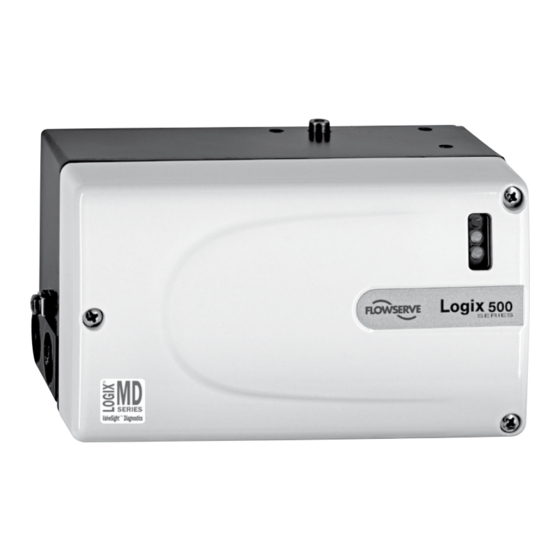
- Page 1 User Instructions Logix 520MD - LGENIM0520-01 11/09 USER INSTRUCTIONS ® Installation Logix 520MD Series Digital Positioner Operation Maintenance FCD LGENIM0520-01 11/09 Experience In Motion...
-
Page 2: Table Of Contents
Trouble Shooting ................15 Protective clothing Limit switches .................. 16 Spare parts ..................17 FLOWSERVE products are often used in problematic Dimensions ..................18 applications (e.g. extremely high pressures, danger- ous, toxic or corrosive mediums). In particular valves with bellows seals point to such applications. When... -
Page 3: Unpacking
FLOWSERVE for repair or service FLOWSERVE must STOP! be provided with a certificate which confirms that the product has been decontaminated and is clean. FLOWSERVE will not accept deliveries if a certificate has not been provided (a form can be obtained from FLOWSERVE). Storage In most cases FLOWSERVE products are manufactured from stainless steel. -
Page 4: Logix 520Md Overview
User Instructions Logix 520MD - LGENIM0520-01 11/09 ® LOgix 520MD OVERViEW Since the positioner is insensitive to supply pressure The Logix 520MD is a two-wire, 4-20 mA input digital valve changes and can handle supply pressures from 1,5 to 6 barg positioner with HART communication. -
Page 5: Principle Of Operation
User Instructions Logix 520MD - LGENIM0520-01 11/09 ® Filter / Regulator for Supply Air 2 Electro-pneumatic Converter Module 1.5 – 6.0 bar (22 – 87 psi) Air Supply Pressure Regulator 1 Digital Control Circuit Inner Loop Piezo Control Inner Loop Position Feedback 4 –... -
Page 6: Tubing
User Instructions Logix 520MD - LGENIM0520-01 11/09 ® Table 10: Connection Table Connection Description Input+ 4..20 mA Input- 4..20 mA +31* Output+ 4..20 mA -32* Output– 4..20 mA Limit switch 1 - separate board 4-20 mA Signal Limit switch 2 - separate board Internal Housing EARTH Terminal Y (0⇒) -
Page 7: Cable Requirements
User Instructions Logix 520MD - LGENIM0520-01 11/09 ® Compliance Controller Voltage 520MD Voltage Figure 3: Compliance Voltage CAUTiOn: Never connect a voltage source directly across rating will allow longer cable runs. In addition to cable the positioner terminals. This could cause permanent capacitance, the network resistance also affects the circuit board damage. -
Page 8: Startup
“Configuration” and “Cal” boxes to the desired control An electromagnetic line filter can be used to further options. eliminate noise (FLOWSERVE Part Number 10156843). nOTE: The switch settings in the Configuration box are activated only by pressing the Quick-Cal button or by... -
Page 9: Calibrations Switches
If the rotary Gain selector switch is set to E with 9.4 Quick-Cal Operation the Auto Tune switch On, a Flowserve nominal The Quick-Cal button is used to locally initiate a response tuning set will be calculated and used. -
Page 10: Factory Reset
User Instructions Logix 520MD - LGENIM0520-01 11/09 ® WARning: When operating using local control of the This option can also be retrofitted in the field. The 4-20 mA valve, the valve will not respond to external commands. analog output board is wired in series with a 12.5 to 40 VDC STOP! Notify proper personnel that the valve will not respond power supply (see Figure 5). -
Page 11: User Instructions Logix 520Md - Lgenim0520-01
User Instructions Logix 520MD - LGENIM0520-01 11/09 ® 4 - 20 IN 4 - 20 OUT 12 VDC – Position Feedback to 40 VDC Current Loop Spannungs- (Logix Output) quelle – Position Command 4 to 20 mA Current Loop Current Source (Logix Input) CAUTION: Isolated Power Sources Required. -
Page 12: Error Codes
User Instructions Logix 520MD - LGENIM0520-01 11/09 ® 11 LiMiT SWiTCH UniT 11.4 Adjusting switches CAUTiOn: The installation of hazardous location electrical equipment must comply with the procedures contained in Use the following procedure to adjust the switches the certificates of conformance. Country specific regulations may apply. - Page 13 This indicator can be disabled. YGGY SignATURE in PROgRESS MODE indicates that a test has been Signatures can only be canceled by Flowserve supplied software. See DTM initiated by Flowserve supplied software screen: Diagnostics. YGGR iniTiALiZing MODE displays a blink sequence 3 times when the Wait for power up to complete.
- Page 14 User Instructions Logix 520MD - LGENIM0520-01 11/09 ® Blink Description Recommendations Code YYYG SUPPLY PRESSURE LOW WARning (user set) indicates that the Regulate the supply pressure at the positioner above 30 PSI (2.1 bar). Reca- supply pressure is below the user set warning limit. Low supply librate pressure sensors.
- Page 15 User Instructions Logix 520MD - LGENIM0520-01 11/09 ® blink Description Recommendations Code RGYY nO MOTiOn TiME OUT ALARM indicates that during calibration, Check linkages and air supply to make sure the system is properly connected. If the time out occurred because the actuator is very large then simply retry the there was no motion of the actuator based on the current stroke Quick cal and the positioner will automatically adjust for a larger actuator by time configuration.
-
Page 16: Trouble Shooting
5. Current source stripping (filtering) 5. Use the HART filter (VHF) available from HART signal Flowserve (FLS part-No. 10156843) Alternatively a 250Ω and a 22 µF capacitor, installed according to the following schematic drawing can be used to establish communication 250Ω... -
Page 17: Spare Parts
Mounting Kits Description Part-no. – IEC 534 part 6 (FloTop, Kämmer KA, Kämmer KP, and standard NAMUR linear valves) 213619.999.000 – Rotary VDI/VDE 3845 (DIN ISO 5211) 188151.999.000 – Flowserve direct mounting 214004.999.000 – Linear VDI / VDE 3847 255242.999.000... -
Page 18: Dimensions
64.10 (VDI/VDE 3845, NAMUR) 2.52 28.60 28.60 1.13 1.13 53.00 2.09 100.00 57.20 35.40 3.94 2.25 1.39 17.70 17.70 M8X1,25 OR 5/16"-18UNC 35.40 1.39 BACK VIEW INCH 57.20 2.25 Figure 10: Dimensional Drawing for the Logix 520MD Series Digital Positioner... - Page 19 User Instructions Logix 520MD - LGENIM0520-01 11/09 FIG. 6 - DIMENSIONAL DRAWING FOR OPTIONS ® SINGLE PRESSURE GAUGE 1/4" NPT 100.00 3.94 216.18 8.51 AUXILIARY OPTIONS - “GA” (GAUGE ADAPTER) TWO PRESSURE GAUGES 100.00 3.94 1/4" NPT 216.87 8.54 AUXILIARY OPTIONS - “GM” (GAUGE MANIFOLD) 47.63 DOMED 1.88...
Need help?
Do you have a question about the Logix 520MD Series and is the answer not in the manual?
Questions and answers