Table of Contents
Advertisement
T h e B e s t W a y
T o G o
A b o u t Y o u r
B u s i n e s s
WARNING
READ THE OPERATOR'S MANUAL BEFORE OPERATING
THIS VEHICLE.
The operator's manual contains important information
regarding the safe operation of this vehicle.
D
Service and Replacement
Parts Manual
Model Numbers:
SS-025-34
SS-025-36
SS-025-46
MX-026-00
Ending Serial Number: See Introduction Chapter
MANUAL MS-534-13
Starting Serial Number: 201627
Advertisement
Chapters
Table of Contents

Related Manuals for Taylor-Dunn SS-025-34


Summary of Contents for Taylor-Dunn SS-025-34
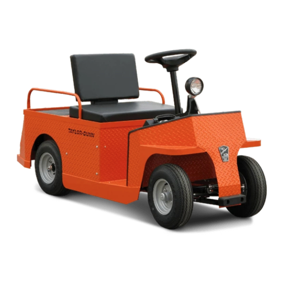
- Page 1 Service and Replacement Parts Manual MANUAL MS-534-13 Model Numbers: SS-025-34 SS-025-36 SS-025-46 MX-026-00 T h e B e s t W a y T o G o A b o u t Y o u r B u s i n e s s WARNING READ THE OPERATOR’S MANUAL BEFORE OPERATING...
- Page 2 Service Advisor at your local dealership. Taylor-Dunn has a worldwide dealer and distribution network to provide replacement parts and service for our vehicles. Refer to our web site, www.taylor-dunn.com, for a dealer lookup application. Originally 3/31/2016 Revision D, 7/13/2018, contents subject to change without notice ®...
- Page 3 Taylor-Dunn Contact information Service, Parts, Sales: Taylor-Dunn has a network of dealers distributed around the globe to support our vehicles. Information regarding vehicle sales, replacement parts, or service should be obtained through your local dealer. A dealer locator can be found on the Taylor-Dunn website at www.taylor-dunn.com.
- Page 4 Decades of experience are an invaluable asset, and it is an asset we cherish and protect. Our guiding principle is to provide application- specific solutions, which are reliable, efficient, and economical. Our domestic and international network of quality Taylor-Dunn Dealers and Parts & Service Support keeps our customers moving. Tiger Tractor: Tiger manufacturing has become a leading manufacturer of internal combustion industrial tractors and ground support equipment.
-
Page 5: Table Of Contents
Master Table of Contents Note: Each section title page contains a section table of contents Introduction ............7 Service/Maintenance Guidelines....13 Special Tool List ..........19 Tool List ..............20 Lubrication ............23 Preventative Maintenance ......27 Front Axle ............31 Steering ............37 Drive Axle-D1 ...........45 Brakes...............53 Drive Motor ............59 Motor Controller ..........67 Charger .............71... - Page 7 Table of Contents Introduction About this manual ...........8 Who Should Read This Manual ......8 How To Use This Manual ........8 Conventions ............9 Signal Words and Their Definitions: ......9 Responsibilities ..........10 How to Identify Your Vehicle ......11 Web Site Registration ........11 WARNING This section is one section of a complete service manual.
-
Page 8: Introduction
Taylor-Dunn is not to be held liable for errors in this manual or any consequential damage that results from the use of this manual. -
Page 9: Introduction
Introduction SS and MX Models, DC System Conventions Symbols and/or words used to define Dangers, Warnings, Cautions, and Notices are found throughout this manual. The “Words” in this context will be referred to as “Signal words.” The words defined here as “signal words” may be used elsewhere in the text of this document without being a signal word. -
Page 10: Responsibilities
Of the Service Personnel... WARNING The only personnel authorized to repair, modify, or adjust any part of this or any Taylor-Dunn vehicle is a factory authorized service technician. Repairs made by unauthorized personnel may result in damage to the vehicles systems which could lead to an unsafe condition resulting in severe bodily injury and/or property damage. -
Page 11: How To Identify Your Vehicle
WEB SITE REGISTRATION Registering on the Taylor-Dunn web site will give you access to a wealth of information about your vehicle and the entire Taylor- Dunn line of vehicles. Your contact information will remain confidential and will not be shared outside of the Taylor-Dunn corporation. - Page 12 Notes Introduction SS and MX Models, DC System Page-12 MS-534-13...
- Page 13 Table of Contents Service/Maintenance Guidelines READ ME FIRST-Maintenance Guidelines and General instructions .........14 Vehicle Modifications ........15 Replacement Parts ..........16 Using Non-OEM Replacement Components ...16 PM Checklist, SS-536, SS546, MX-600 ...17 PM Checklist, SS-534 ........18...
-
Page 14: Service/Maintenance Guidelines
BEFORE STARTING ANY REPAIRS The only personnel authorized to repair, modify, or adjust any part of this or any Taylor-Dunn vehicle is 1) Make sure the Start switch is in the “OFF” position, a factory authorized service technician. Repairs made then remove the key. -
Page 15: Service/Maintenance Guidelines
Contact the factory for information regarding available alternate program settings. Taylor-Dunn will only authorize the use of settings obtained from the factory for a specific vehicle. Any other alterations to the programming ARE NOT AUTHORIZED and is at your own risk. -
Page 16: Replacement Parts
To maintain peak performance, always use original Taylor-Dunn replacement parts intended for use on your vehicle. Taylor-Dunn components are designed and tested for use on specific Taylor-Dunn model vehicles. Only use the correct Taylor-Dunn replacement components for your Taylor-Dunn vehicle. -
Page 17: Pm Checklist, Ss-536, Ss546, Mx-600
Service/Maintenance Guidelines SS and MX Models, DC System PM CHECKLIST, SS-536, SS546, MX-600 Taylor-Dunn Preventative Maintenance Schedule for SS-536, SS-546, MX-600 Date: ________________________ Model #: ________________ Hour Meter: _______________ Inspected By: ________________________ Serial #: ________________ Serviced By: ________________________ Unit ID#: ________________... -
Page 18: Pm Checklist, Ss-534
Service/Maintenance Guidelines SS and MX Models, DC System PM CHECKLIST, SS-534 Taylor-Dunn Preventative Maintenance Schedule for SS-534 Date: ________________________ Model #: ________________ Hour Meter: _______________ Inspected By: ________________________ Serial #: ________________ Serviced By: ________________________ Unit ID#: ________________ Interval Service Service... - Page 19 Table of Contents Special Tool List Tool List ............20 Controller Programming: .........20 Troubleshooting Guide ........22...
-
Page 20: Tool List
Tool List SS and MX Models, DC System TOOL LIST The tools shown here are generic for servicing Taylor-Dunn vehicles. Not all tools will be required for servicing this vehicle. 62-027-32: Throttle Module Analyzer 75-089-00: Throttle Module Test Harness Tests the throttle module in or out of the... - Page 21 Removes 0.062 diameter pins from Molex Removes 0.093 diameter pins from Molex rectangular harness connectors. Not rectangular harness connectors. Not available from Taylor-Dunn. Purchase from available from Taylor-Dunn. Purchase from any local electronics distributor. any local electronics distributor. MS-534-13...
- Page 22 Tool List SS and MX Models, DC System TROUBLESHOOTING GUIDE This is a general troubleshooting guide for various mechanical faults. Refer to the electrical troubleshooting chapter for checking the electronic motor control system. This list is provided as a guide only. It is not all inclusive of causes that may result in a specific symptom. Symptom Suspect Component or System Action...
- Page 23 Table of Contents Lubrication Lubrication and Fluids Chart ......24 Hazardous Waste Disposal ......24 Lubrication Diagram ........25...
- Page 24 Lubrication SS and MX Models, DC System LUBRICATION AND FLUIDS CHART Assembly Item # Component Capacity Lubricant Front Axle: King Pin (SS-546) NLGI Grade 2 lithium multi-purpose grease Axle Pivot (SS-546) NLGI Grade 2 lithium high temp Bearing Grease Wheel Bearing 1 or 2 NLGI Grade 2 lithium multi-purpose grease Fork Spindle Bearing...
-
Page 25: Lubrication
Lubrication SS and MX Models, DC System LUBRICATION DIAGRAM SS-534 from Rear (#9 on top) SS-536, SS-546, MX from Bottom MS-534-13 Page 25... - Page 26 Notes Lubrication SS and MX Models, DC System Page 26 MS-534-13...
- Page 27 Table of Contents Preventative Maintenance Daily Visual Inspection ........28 Pre-Operation Inspection ........28 Maintenance Schedule ........29 Maintenance Guidelines for Severe Duty Applications .............29 WARNING This section is one section of a complete service manual. Before starting any procedure, read all warnings and instructions that are located in the Service Guidelines chapter.
-
Page 28: Daily Visual Inspection
PM Schedule SS and MX Models, DC System DAILY VISUAL INSPECTION PRE-OPERATION INSPECTION WARNING WARNING This section is one section of a complete service This section is one section of a complete service manual. Before starting any procedure, read all manual. -
Page 29: Maintenance Schedule
PM Schedule SS and MX Models, DC System MAINTENANCE SCHEDULE A PM Check List is available and included on the documentation CD provided with your vehicle. The document numbers are: • PM-0017: Models SS-536, 546, and MX-600 • PM-0018: Model SS-534 First 25 hours of Operation Every 6 Months or 1,000 hours) Re-torque wheel nuts. - Page 30 Notes PM Schedule SS and MX Models, DC System Page 30 MS-534-13...
- Page 31 Table of Contents Front Axle Inspect Front Wheel Bearings (3-wheel) ..32 Inspect Front Wheel Bearings (4-Wheel) ..32 Adjust Front Wheel Bearings (3-wheel) ..33 Adjust Front Wheel Bearings (4-wheel) ..33 Replace Front Wheel Bearings (3-wheel) ..34 Replace Front Wheel Bearings (4-Wheel) ..34 Axle Shaft, Remove/Install (3-wheel) .....35 Axle Assembly, Remove/Install (4-wheel) ..35 Remove ..............35...
-
Page 32: Front Axle
Front Axle SS and MX Models, DC System INSPECT FRONT WHEEL INSPECT FRONT WHEEL BEARINGS (3-WHEEL) BEARINGS (4-WHEEL) WARNING WARNING This section is one section of a complete service This section is one section of a complete service manual. Before starting any procedure, read all manual. -
Page 33: Adjust Front Wheel Bearings (3-Wheel)
Front Axle SS and MX Models, DC System ADJUST FRONT WHEEL BEARINGS ADJUST FRONT WHEEL BEARINGS (3-WHEEL) (4-WHEEL) WARNING WARNING This section is one section of a complete service This section is one section of a complete service manual. Before starting any procedure, read all manual. -
Page 34: Front Axle
Front Axle SS and MX Models, DC System REPLACE FRONT WHEEL REPLACE FRONT WHEEL BEARINGS (3-WHEEL) BEARINGS (4-WHEEL) WARNING WARNING This section is one section of a complete service This section is one section of a complete service manual. Before starting any procedure, read all manual. -
Page 35: Axle Shaft, Remove/Install (3-Wheel)
Front Axle SS and MX Models, DC System AXLE SHAFT, REMOVE/INSTALL AXLE ASSEMBLY, REMOVE/ (3-WHEEL) INSTALL (4-WHEEL) WARNING WARNING This section is one section of a complete service This section is one section of a complete service manual. Before starting any procedure, read all manual. -
Page 36: Hardware Torque
Front Axle SS and MX Models, DC System HARDWARE TORQUE Notes Description Foot Pounds Newton Meters Ball Joint Clamp 28-32 37.9-43.4 Rod End Stud Nut 20-25 27.1-33.9 Rod End Jam Nut 20-25 27.1-33.9 Page 36 MS-534-13... - Page 37 Table of Contents Steering Inspect Rod Ends ..........38 Replace Rod End ..........38 Front End Alignment, SS-546 ......39 Front End Alignment, SS-534, SS-536, MX-600 ............39 Replace Steering Tiller ........40 Replace Steering Wheel ........40 Replace Steering Gear, SS-534 ......41 Replace Steering Gear, SS-536, SS-546, MX-600 ......41 Front Fork ............43 Installation ...............43...
-
Page 38: Inspect Rod Ends
Steering SS and MX Models, DC System INSPECT ROD ENDS REPLACE ROD END WARNING WARNING This section is one section of a complete service This section is one section of a complete service manual. Before starting any procedure, read all manual. -
Page 39: Front End Alignment, Ss-546
Steering SS and MX Models, DC System FRONT END ALIGNMENT, SS-546 FRONT END ALIGNMENT, SS-534, WARNING SS-536, MX-600 There are no alignment adjustement to the 3-wheel This section is one section of a complete service steering. manual. Before starting any procedure, read all If the vehicle pulls to the left or right then the fork or warnings and instructions that are located in the frame is bent. -
Page 40: Replace Steering Tiller
Steering SS and MX Models, DC System REPLACE STEERING TILLER REPLACE STEERING WHEEL WARNING WARNING This section is one section of a complete service This section is one section of a complete service manual. Before starting any procedure, read all manual. -
Page 41: Replace Steering Gear, Ss-534
Steering SS and MX Models, DC System REPLACE STEERING GEAR, SS-534 REPLACE STEERING GEAR, WARNING SS-536, SS-546, MX-600 WARNING This section is one section of a complete service manual. Before starting any procedure, read all This section is one section of a complete service warnings and instructions that are located in the manual. - Page 42 Steering SS and MX Models, DC System STEERING GEAR, SS-536, SS-546, MX-600 WARNING This section is one section of a complete service manual. Before starting any procedure, read all warnings and instructions that are located in the Service Guidelines chapter. 1: Remove the steering gear from the vehicle.
-
Page 43: Front Fork
Steering SS and MX Models, DC System FRONT FORK WARNING This section is one section of a complete service manual. Before starting any procedure, read all warnings and instructions that are located in the Service Guidelines chapter. Installation Note: It is recommended to replace the grease seal any time the fork is removed from the vehicle. -
Page 44: Hardware Torque
Steering SS and MX Models, DC System HARDWARE TORQUE Description Foot Pounds Newton Meters Notes Ball Joint Clamp 28-32 37.9-43.4 Rod End Stud Nut 20-25 27.1-33.9 Rod End Jam Nut 20-25 27.1-33.9 Ball Joint Castle Nut 40-45 54.2-64.2 Tiller Pinch Bolt 40-43 54.2-61.4 Steering Wheel Nut... - Page 45 Table of Contents Drive Axle-D1 Check Oil Level ..........46 Change Oil ............46 Axle Shaft ............47 Remove ..............47 Install ...............47 Axle Bearings...........47 Remove/Install ............47 Drive Motor ............48 Remove ..............48 Install ...............48 Differential Case ..........49 Disassemble ............49 Assemble ..............51 Hardware Torque ..........52 WARNING This section is one section of a complete service manual.
-
Page 46: Drive Axle-D1
Drive Axle SS and MX Models, DC System CHECK OIL LEVEL CHANGE OIL WARNING WARNING This section is one section of a complete service This section is one section of a complete service manual. Before starting any procedure, read all manual. -
Page 47: Drive Axle-D1
Drive Axle SS and MX Models, DC System AXLE SHAFT AXLE BEARINGS Note: The axle must be removed from the WARNING transmission for this procedure. Refer to Remove and Install Axle for information regarding removing the rear axle. This section is one section of a complete service WARNING manual. -
Page 48: Drive Motor
Drive Axle SS and MX Models, DC System DRIVE MOTOR WARNING This section is one section of a complete service manual. Before starting any procedure, read all warnings and instructions that are located in the Service Guidelines chapter. Remove Note: In some vehicle configurations the transmission assembly will have to be removed to allow clearance to remove the motor. -
Page 49: Differential Case
Drive Axle SS and MX Models, DC System DIFFERENTIAL CASE Disassemble 1: Remove the transmission from the vehicle. Refer to Transmission-Remove section for information on removing the transmission. 2: Thoroughly clean the transmission assembly before disassembly. 3: Remove the left and right axles from the transmission assembly. Refer to Rear Axle section for information on removing the axles. - Page 50 Drive Axle SS and MX Models, DC System 12: Using a soft metal or hard wood dowel, drive 16: Remove the circlip from the input shaft. the intermediate shaft through the bearing just 17: Remove the input shaft from the housing. enough to allow clearance for an ID bearing 18: Press the bearings off of the input shaft.
-
Page 51: Assemble
Drive Axle SS and MX Models, DC System Assemble Notes: When pressing bearings, do not press against or support the outer race as this will damage the bearing. All snap rings should fit tightly into their grooves. If a snap ring is loose, then it must be replaced. Do not hit any shaft or component with a hard metal hammer or punch. Pre-lube all bearings, seals and o-rings before assembly. -
Page 52: Hardware Torque
Drive Axle SS and MX Models, DC System HARDWARE TORQUE If hardware is not listed here, refer to standard torque values in the appendix. Description Foot Pounds Newton Meters Motor terminals 7.5-9.1 10.2-12.4 Motor Mounting Bolts 8-10.5 Final Drive Gear Nuts 35-45 48-61 Differential Bearing Cap Bolts... - Page 53 Table of Contents Brakes General Guidelines and Safety.......54 Rear Drum Brake ..........55 Auto-Adjust Brake Mechanism ........55 Inspecting the Auto-Adjust Brake Mechanism ..55 Service Limits ............56 Inspection ..............56 Replace Shoes ............56 Rebuild Disc Brake Body ........57 Brake Adjustment ..........58 Service Brake ............58 Adjust the Service Brake Linkage ......58 Parking Brake ............58 Service Limits ..........58...
-
Page 54: General Guidelines And Safety
SS and MX Models, DC System GENERAL GUIDELINES AND SAFETY WARNING WARNING Taylor-Dunn does not currently supply asbestos This section is one section of a complete service fiber-brake pads/shoes with any vehicle. However, manual. Before starting any procedure, read all... -
Page 55: Rear Drum Brake
Brakes SS and MX Models, DC System REAR DRUM BRAKE WARNING This section is one section of a complete service manual. Before starting any procedure, read all warnings and instructions that are located in the Service Guidelines chapter. Auto-Adjust Brake Mechanism Theory of Operation The auto-adjust mechanism is located on the bottom of the brake assembly. -
Page 56: Service Limits
Brakes SS and MX Models, DC System Service Limits Refer to the table at the end of this section WARNING Inspection 1: Raise the rear of the vehicle and support with jack This section is one section of a complete service stands. -
Page 57: Rebuild Disc Brake Body
Brakes SS and MX Models, DC System REBUILD DISC BRAKE BODY WARNING This section is one section of a complete service manual. Before starting any procedure, read all warnings and instructions that are located in the Service Guidelines chapter. This procedure assumes that the component has been removed from the vehicle. -
Page 58: Brake Adjustment
Brakes SS and MX Models, DC System BRAKE ADJUSTMENT WARNING This section is one section of a complete service manual. Before starting any procedure, read all warnings and instructions that are located in the Service Guidelines chapter. Note: This vehicle is equipped with self-adjusting brakes. - Page 59 Table of Contents Drive Motor Motor Removal and Installation .....60 Disassemble.............60 Assemble............61 Inspection ............62 Brushes ..............62 Armature ..............62 Bearings ..............63 Commutator .............63 Repair ...............64 Brushes ..............64 Commutator .............64 Service Limits ..........65 WARNING This section is one section of a complete service manual.
-
Page 60: Drive Motor
Drive Motor SS and MX Models, DC System MOTOR REMOVAL AND INSTALLATION See the Transmission section for information on removing or installing the motor. DISASSEMBLE WARNING This section is one section of a complete service manual. Before starting any procedure, read all warnings and instructions that are located in the Service Guidelines chapter. -
Page 61: Drive Motor
Drive Motor SS and MX Models, DC System ASSEMBLE WARNING This section is one section of a complete service manual. Before starting any procedure, read all warnings and instructions that are located in the Service Guidelines chapter. 1: Press new bearings into the motor housings and install the circlips. -
Page 62: Inspection
Drive Motor SS and MX Models, DC System INSPECTION Armature WARNING 1: Visually inspect the armature windings for burnt insulation. Burnt insulation is a direct result of motor overheating and could lead to a shorted This section is one section of a complete service armature. -
Page 63: Bearings
Drive Motor SS and MX Models, DC System Bearings Pressing the armature out of the bearings is likely to damage the bearings. Once removed the bearings should be replaced. Commutator 1: Measure the outside diameter of the commutator. • If the commutator is less than the minimum diameter specified in section Service Limits, then the motor must be replaced. -
Page 64: Repair
Drive Motor SS and MX Models, DC System REPAIR WARNING This section is one section of a complete service manual. Before starting any procedure, read all warnings and instructions that are located in the Service Guidelines chapter. Brushes Note: It is recommended that all four brushes be replaced as a set. -
Page 65: Service Limits
Drive Motor SS and MX Models, DC System SERVICE LIMITS WARNING This section is one section of a complete service manual. Before starting any procedure, read all warnings and instructions that are located in the Service Guidelines chapter. Commutator Brush Length Resistance Undercut Depth Motor Specification... - Page 66 Notes Drive Motor SS and MX Models, DC System Page 66 MS-534-13...
- Page 67 Table of Contents Motor Controller Remove/Install ..........68 Inspect ..............68 Troubleshooting ..........68 Repair/Adjustments.........69 Adjustments .............69 Hardware Torque ..........70 WARNING This section is one section of a complete service manual. Before starting any procedure, read all warnings and instructions that are located in the Service Guidelines chapter.
- Page 68 1: Thoroughly clean the controller base and vehicle documentation CD. A replacement CD or hard mounting plate. copy can be purchased from your authorized Taylor-Dunn 2: Install the controller to the mounting plate. distributor or can be downloaded from the Taylor-Dunn 3: Attach the wires to the studs and, using a backup web site.
-
Page 69: Motor Controller
Motor Controller SS and MX Models, DC System REPAIR/ADJUSTMENTS WARNING This section is one section of a complete service manual. Before starting any procedure, read all warnings and instructions that are located in the Service Guidelines chapter. Repairs There are no internally serviceable components in the motor speed controller. - Page 70 Motor Controller SS and MX Models, DC System HARDWARE TORQUE If hardware is not listed here, refer to standard torque values in the appendix. Notes Description Inch Pounds Newton Meters Terminal hardware 8.13 Adjustment plugs 0.90 Page 70 MS-534-13...
- Page 71 Table of Contents Charger Remove/Install ..........72 Troubleshooting ..........72 WARNING This section is one section of a complete service manual. Before starting any procedure, read all warnings and instructions that are located in the Service Guidelines chapter.
- Page 72 The manual part number is M7-001-69 and was provided on the original vehicle CD. A hard copy can be purchased WARNING from your authorized Taylor-Dunn distributor or can be downloaded from the Taylor-Dunn web site. HIGH VOLTAGE. Disconnect the batteries and make sure that the AC power cord has been unplugged before disconnecting any wires or removing the cover of the charger.
- Page 73 Table of Contents Tires & Wheels Inflation .............74 Air pressure .............74 Tread Wear ............75 Rotation ............75 Changing Tire/Wheel Assembly .....76 Replace the Tire (pneumatic) ......76 Repair the Tire (pneumatic) ......76 Hardware Torque ..........77 WARNING This section is one section of a complete service manual.
-
Page 74: Tires & Wheels
Tires & Wheels SS and MX Models, DC System INFLATION WARNING WARNING Incorrect tire inflation can result in sudden failure of This section is one section of a complete service the tire and/or braking / steering problems leading manual. Before starting any procedure, read all to loss of control of the vehicle. -
Page 75: Tread Wear
Tires & Wheels SS and MX Models, DC System TREAD WEAR WARNING WARNING This section is one section of a complete service DO NOT operate a vehicle if the cord is manual. Before starting any procedure, read all visible on any tire (see illustration). A tire warnings and instructions that are located in the in this conditions may suddenly fail at Service Guidelines chapter. -
Page 76: Changing Tire/Wheel Assembly
Tires & Wheels SS and MX Models, DC System CHANGING TIRE/WHEEL REPLACE THE TIRE (PNEUMATIC) WARNING ASSEMBLY WARNING This section is one section of a complete service manual. Before starting any procedure, read all warnings and instructions that are located in the This section is one section of a complete service Service Guidelines chapter. -
Page 77: Hardware Torque
Tires & Wheels SS and MX Models, DC System HARDWARE TORQUE If hardware is not listed here, refer to standard torque values in the appendix. Description Foot Pounds Newton Meters Wheel nut MS-534-13 Page 77... - Page 78 Notes Tires & Wheels SS and MX Models, DC System Page 78 MS-534-13...
- Page 79 Table of Contents Batteries General Guidelines and Safety.......80 Cleaning ............81 Charging ............81 Watering ............81 Testing ..............82 Specific Gravity ............82 Storing ..............82 Storage ..............82 Returning to Service ..........82 Remove/Install ..........83 Industrial Battery or Lift Out Battery Pack ....83 Individual Batteries ..........83 Hardware Torque ..........84 WARNING This section is one section of a complete service...
-
Page 80: General Guidelines And Safety
Batteries SS and MX Models, DC System GENERAL GUIDELINES AND SAFETY WARNING NOTICE Battery electrolyte will stain and corrode most This section is one section of a complete service surfaces. Immediately and thoroughly clean any manual. Before starting any procedure, read all surface outside of the battery that the battery warnings and instructions that are located in the electrolyte comes in contact with. -
Page 81: Cleaning
Batteries SS and MX Models, DC System CLEANING WATERING WARNING WARNING This section is one section of a complete service This section is one section of a complete service manual. Before starting any procedure, read all manual. Before starting any procedure, read all warnings and instructions that are located in the warnings and instructions that are located in the Service Guidelines chapter and beginning of this... -
Page 82: Testing
Batteries SS and MX Models, DC System TESTING STORING WARNING WARNING This section is one section of a complete service This section is one section of a complete service manual. Before starting any procedure, read all manual. Before starting any procedure, read all warnings and instructions that are located in the warnings and instructions that are located in the Service Guidelines chapter and beginning of this... -
Page 83: Remove/Install
Batteries SS and MX Models, DC System REMOVE/INSTALL WARNING WARNING This section is one section of a complete service Do not allow the loose battery cables to contact any manual. Before starting any procedure, read all other parts of the vehicle as this could cause in a warnings and instructions that are located in the short circuit resulting severe bodily injury or damage Service Guidelines chapter and beginning of this... -
Page 84: Hardware Torque
Batteries SS and MX Models, DC System HARDWARE TORQUE If hardware is not listed here, refer to standard torque values in the appendix. Description Inch Pounds Newton Meters Battery terminal, Trojan bolt 95-105 11-12 Notes Battery terminal, Trojan stud 95-105 11-12 Battery terminal, T/D bolt Page 84... - Page 85 Table of Contents Suspension Rear Coil Spring and Shock, SS-534 .....86 Remove/Install ............86 Rear Coil Springs, SS-536, SS-546 ............86 Remove/Install ............86 Raising the Rear of the Vehicle ......87 Front Fork Springs ..........87 WARNING This section is one section of a complete service manual.
- Page 86 Suspension SS and MX Models, DC System REAR COIL SPRING AND SHOCK, REAR COIL SPRINGS, SS-536, SS-534 SS-546 WARNING WARNING This section is one section of a complete service This section is one section of a complete service manual. Before starting any procedure, read all manual.
- Page 87 Suspension SS and MX Models, DC System FRONT FORK SPRINGS RAISING THE REAR OF THE VEHICLE The front fork springs are an integral part of the front WARNING fork assembly. If the springs require replacement then the fork NEVER lift both rear wheels off of the ground using assembly should be replaced.
- Page 88 Notes Suspension SS and MX Models, DC System Page 88 MS-534-13...
- Page 89 Table of Contents Wire Diagram Diagram Part Numbers........90 WARNING This section is one section of a complete service manual. Before starting any procedure, read all warnings and instructions that are located in the Service Guidelines chapter.
- Page 90 Vehicle Documentation CD provided with the vehicle. The diagram #’s for there vehicles: • SCH-00072: SS-534, SS-536, SS-546 • SCH-00032: MX-600 This vehicle diagrams as well as other Taylor-Dunn vehicle diagrams can be downloaded from the Taylor-Dunn web site at www.taylor-dunn.com. Page 90 MS-534-13...
- Page 91 Table of Contents Hardware Information Torque Guidelines for Standard hardware ..92 Hardware Identification ..........92 Hex Nuts ..............93 Hex Lock Nuts (stover) ..........93 Other Nuts ...............93 Generic Torque Values ..........94 Replacing Hardware ........96 WARNING This section is one section of a complete service manual.
-
Page 92: Torque Guidelines For Standard Hardware
Hardware SS and MX Models, DC System TORQUE GUIDELINES FOR STANDARD HARDWARE Note: Torque values specified are for clean dry threads. Note: Torque value used should be for lowest grade of hardware used. If a grade 2 nut is used on a grade 8 bolt, use grade 2 torque value. Hardware Identification Hex Head Bolts and Screws The grade of SAE bolts and screws are identified by markings on the head... -
Page 93: Hex Nuts
‘2’ hex nuts, Grade ‘B’ as Grade ‘5’ and Grade ‘C’ as Grade ‘8’. NOTE: Nuts with no markings are to be treated as S.A.E. Grade A S.A.E. Grade B S.A.E. Grade C Grade L’9 Other Nuts Other nuts used by Taylor-Dunn ® should be treated as S.A.E. grade A MS-534-13 Page 93... -
Page 94: Generic Torque Values
Hardware SS and MX Models, DC System Generic Torque Values All torque values are for clean dry zinc plated threads in noncritical steel assemblies of the same hardness specification. Reduce torque approximately 10-15% for lubricated threads. Refer to the service section assembly procedure for critical torque values. Imperial (inch), Foot Pounds Imperial (inch), Newton Meters Grade, SAE... - Page 95 Hardware SS and MX Models, DC System All torque values are for clean dry zinc plated threads in noncritical steel assemblies of the same hardess specification. Reduce torque approximately 10-15% for lubricated threads. Refer to the service section assembly procedure for critical torque values. Metric, Newton Meters Metric, Foot Pounds Grade, N-m...
-
Page 96: Replacing Hardware
Hardware SS and MX Models, DC System REPLACING HARDWARE WARNING This section is one section of a complete service manual. Before starting any procedure, read all warnings and instructions that are located in the Service Guidelines chapter. WARNING Failure to follow the following guidelines may result in failure of the hardware resulting in severe bodily injury or property damage: •... - Page 97 TABLE OF CONTENTS Replacement Parts Ordering Parts for Your Vehicle .....98 Taylor-Dunn Web Site Information ....98 Identifying your vehicle ........99 Axle Assembly, Front ........100 Axle Shaft Assembly, Rear ......102 Axle Assembly, Rear 3rd Member, SS-534 ..104 Axle Assembly, Belt Drive, SS-534....105 TransAxle Assembly, SS-536, SS-346, MX600 ............106...
-
Page 98: Replacement Parts
ORDERING PARTS FOR YOUR VEHICLE WARNING The only personnel authorized to repair, modify, or adjust any part of this or any Taylor-Dunn vehicle is a factory authorized service technician. Repairs made by unauthorized personnel may result in damage to the vehicles systems which could lead to an unsafe condition resulting in severe bodily injury and/or property damage. -
Page 99: Replacement Parts
Replacement Parts SS and MX Models, DC System My Vehicle information Serial Number: Date Purchased: Date Delivered: Dealer Purchased From: Salesman Name: My local Parts Dealer: IDENTIFYING YOUR VEHICLE Whenever necessary the model of the vehicle is identified with the parts that are specific to that model. If a model identification is not specified in the diagram heading or within the parts table, then the part can is used in all models. -
Page 100: Axle Assembly, Front
Replacement Parts SS and MX Models, DC System AXLE ASSEMBLY, FRONT SS-534, SS-536, MX-600 SS-546 Page 100 MS-534-13... - Page 101 Replacement Parts SS and MX Models, DC System Axle Assembly, Front (SS-534, SS-536, MX-600) Item No. Part No. Description 16-206-00 Spacer 45-308-00 Oil Seal 80-105-00 Bearing Race 80-015-00 Tapered Roller Bearing 15-010-10 Front Axle 85-140-10 Spring 14-079-20 Fork 97-100-00 Woodruff Key 88-229-81 3/4”...
-
Page 102: Axle Shaft Assembly, Rear
Replacement Parts SS and MX Models, DC System AXLE SHAFT ASSEMBLY, REAR SS-536, SS-546, MX-600 Page 102 MS-534-13... - Page 103 Replacement Parts SS and MX Models, DC System Axle Assembly, Rear SS-534 Item No. Part No. Description 85-140-00 2-7/16” X 6-1/4” Spring 96-240-00 1/2” X 4” Bolt 98-601-00 Rubber Grommet, 1/2” ID 88-149-81 1/2”NC Locknut 45-045-00 Rear Axle Bearing Gasket 45-301-00 Oil Seal 32-515-00...
-
Page 104: Axle Assembly, Rear 3Rd Member, Ss-534
Replacement Parts SS and MX Models, DC System AXLE ASSEMBLY, REAR 3RD MEMBER, SS-534 Page 104 MS-534-13... -
Page 105: Axle Assembly, Belt Drive, Ss-534
Replacement Parts SS and MX Models, DC System Axle Assembly, 3rd Member, SS-534 Item No. Part No. Description 3rd member Housing (1.784 ID Carrier Bearing) 88-119-80 3/8” NF Nut Differential Assembly 80-128-00 Carrier Bearing Race 80-512-00 Carrier Bearing 31-234-50 Ring and Pinion Gear Set , 3.00 ratio 0 or 1 31-239-00 Ring and Pinion Gear Set , 5.43 ratio... -
Page 106: Transaxle Assembly, Ss-536, Ss-346, Mx600
Replacement Parts SS and MX Models, DC System TRANSAXLE ASSEMBLY, SS-536, SS-346, MX600 Page 106 MS-534-13... - Page 107 Replacement Parts SS and MX Models, DC System Axle Assembly, Transaxle, SS-536, SS-546, MX-600 Spec # 012AJ311-1 Item No. Part No. Description 4S-150-10 Complete transmission assembly 41-280-10 Differential Housing Assy 80-480-10 Pinion Bearing 31-265-00 Gear Set 80-480-15 Shaft Bearing 88-840-12 Snap Ring 80-715-10 O-Ring...
-
Page 108: Battery
Replacement Parts SS and MX Models, DC System BATTERY Item No. Part No. Description 75-237-00 Battery jumper 77-043-00 Battery, T-605 0 or 4 77-042-00 Battery, T-105 0 or 4 77-047-00 Battery, T-145 0 or 4 50-243-10 Battery rod 1 or 2 50-250-00 Battery hold down 1 or 2... -
Page 109: Brakes, Linkage Ss-534
Replacement Parts SS and MX Models, DC System BRAKES, LINKAGE SS-534 Item No. Part No. Description 88-140-14 1/2” NC X 1-1/2” Hex Head Cap Screw 98-200-00 Brake Pedal Pad, Rubber 88-089-81 1/2” NC Locknut 01-534-67 Brake Pedal Arm 88-140-14 1/2” NC X 1-1/2” Hex Head Cap Screw 96-772-00 3/8”... -
Page 110: Brakes, Linkage Ss-536, Ss-546, Mx-600
Replacement Parts SS and MX Models, DC System BRAKES, LINKAGE SS-536, SS-546, MX-600 Item No. Part No. Description 88-140-13 1/2” X 1/4” NC Bolt 02-536-09 Pedal Lock 98-200-00 Pedal Pad 88-149-81 1/2” NC Locknut 88-527-11 1/8” X 1” Cotter Pin 96-762-00 Clevis 88-119-81... -
Page 111: Brakes, Ss-534
Replacement Parts SS and MX Models, DC System BRAKES, SS-534 Item No. Part No. Description 41-660-60 Kit, Brake Band 41-532-00 Brake drum 41-380-10 Bracket 88-080-11 5/16NC x 1 Bolt 88-089-81 5/16 Lock Nut 85-270-00 Spring See pedal linkage Link MS-534-13 * Not available at time of printing Page 111... -
Page 112: Brakes, Ss-536, 546, Mx-600
Replacement Parts SS and MX Models, DC System BRAKES, SS-536, 546, MX-600 Item No. Part No. Description 85-344-60 Spring Kit 41-634-00 Brake Shoes (Shows 1 Set) 41-344-98 Complete Brake Assembly, Left 41-344-99 Complete Brake Assembly, Right Page 112 MS-534-13... -
Page 113: Charger, Signet
Replacement Parts SS and MX Models, DC System CHARGER, SIGNET Note: The harness connectors and AC plug are not included with the charger. Model HBS Charger PART # DESCRIPTION 79-302-20 24 volt Flooded Batteries (WET, FLA) Note: There are no user serviceable components inside the charger Note: The charger AC cord is an integral part of the charger. - Page 114 Replacement Parts SS and MX Models, DC System Model 14400-31 7105-01 12750 9513-31 13760 22730 Part Number 79-302-50 79-300-50 79-300-55E 79-302-10 79-302-15 79-303-05 Type 24LC40-8ET 24LC25-8ET 24LC25-8ET 24LC40-8ET 24LC40-8ET 24LC25-8ET AC Voltage/Hz/Amps 230/50/7 230/50/4 230/50/4 115/60/13 115/60/13 115/60/8 DC Voltage/Amps 24/40 24/25 24/25...
-
Page 115: Control System, Motor Speed Control
Replacement Parts SS and MX Models, DC System CONTROL SYSTEM, MOTOR SPEED CONTROL Item No. Part No. Description 88-838-06 #14 X 1/2” Pan Head Screw 62-204-00 Motor Controller 72-501-43 Direction Control Solenoids 61-838-41 5/8” X 1-1/2” Bus Bar 88-088-62 5/16” Lock washer 88-099-91 5/16”... -
Page 116: Control System, Instrument Panel
Replacement Parts SS and MX Models, DC System CONTROL SYSTEM, INSTRUMENT PANEL SS-534, SS-536, SS-546 MX-600 Item No. Part No. Description 71-122-20 Horn Switch 71-120-10 Start Switch 71-039-11 Light Switch, SS models 71-100-00 Light Switch, MX model 74--009-10 Battery Status Gauge 71-039-11 Auxiliary Swtich, SS models 71-100-00... -
Page 117: Decals
Replacement Parts SS and MX Models, DC System DECALS Item No. Part No. Description 94-384-00 How to apply park brake 94-309-50 Park Brake Warning 94-313-20 Safety warning 94-301-43 Arms and Legs, SS-534, SS-536, MX-600 94-301-42 Arms and Legs SS-546 94-384-01 Not a Motor Vehicle 94-384-14 When Leaving Vehicle... -
Page 118: Electrical, Miscellaneous
Replacement Parts SS and MX Models, DC System ELECTRICAL, MISCELLANEOUS Electrical Item No. Part No. Description 96-624-00 Clamp, 1/4 Jiffy Clip 96-625-00 Clamp, 5/16 Jiffy Clip 96-626-00 Clamp, 7/8 Jiffy Clip 96-640-00 Clamp, 3/16 Push Mount 96-642-00 Wire harness Clip, push mount 96-650-01 Wire Harness Clip, stick on 96-629-80 (not shown) Clamp, Rubber Lined 3/16 ID... -
Page 119: Frame And Body, Deckboards
Replacement Parts SS and MX Models, DC System FRAME AND BODY, DECKBOARDS Item No. Part No. Description 90-408-10 Deck, SS-536, SS-546 90-409-00 Deck, SS-534 94-025-51 Deck Trim, SS-534 50-112-00 Deck Prop Rod, SS-534 88-587-90 Retainer, Prop Rod 91-809-00 Mount, Prop Rod 90-408-20 Deck, MX-600 97-840-00... -
Page 120: Frame And Body, Toolbox, Mx-600
Replacement Parts SS and MX Models, DC System FRAME AND BODY, TOOLBOX, MX-600 Item No. Part No. Description 91-340-25 Tool Chest 00-300-02 Trim 94-400-32 Double Sided Tape 3 ft 88-140-11 1/2”NC X 1” Hex Head Bolt 88-148-61 1/2” SAE Washer 88-159-84 1/2”NC Locknut Not Shown 91-340-21... -
Page 121: Hitches
Replacement Parts SS and MX Models, DC System HITCHES WARNING DO NOT install a trailer hitch unless the vehicle was configured for towing from the factory. Field kits are not available. DO NOT transport passengers when towing a trailer; The passenger may be severely injured if contacted by the trailer tongue. -
Page 122: Lights
Replacement Parts SS and MX Models, DC System LIGHTS Item No. Part No. Description 72-005-00 Headlight 71-505-05 Headlight Mount, geared steering option 75-166-35 Harness, MX 6-00 72-022-00 Tail light, 4” Round 72-025-00 Tail Light, Oval 71-111-00 Brake light switch 0 or 1 72-022-51 Round Rubber Grommet 72-025-51... -
Page 123: Motor
Replacement Parts SS and MX Models, DC System MOTOR Motor Item No. Part No. Description 70-049-05 Motor assembly, SS-536, SS-546, MX-600 70-049-00 Motor assembly, SS-534 Field assembly Armature 70-180-00 Brush holder PKIT-00022 Brush springs (four) PKIT-00064 Brush pair (two) 70-417-00 Bearing retainer 80-212-00 Bearing, rear... -
Page 124: Motor Mount
Replacement Parts SS and MX Models, DC System MOTOR MOUNT Motor Mount, SS-534 Item No. Part No. Description 00-380-96 Motor mount 88-100-11 Bolt See belt drive Pulley 30-117-00 70-422-00 Strap, motor mount 88-109-87 97-100-00 Woodruf key Motor Mount, SS-536-SS-546, MX-600 Item No. -
Page 125: Seats
Replacement Parts SS and MX Models, DC System SEATS Item No. Part No. Description 93-004-00 Seat back, SS-536, SS-546 90-144-00 Seat Back, SS-534 (optional) 90-144-00 Seat Back, MX-600 93-005-00 Seat Cushion, SS-536, SS-546 90-166-00 Seat Cushion, SS-534 96-006-00 Seat Cushion, MX-600 90-109-50 **Seat Frame, Back, Fold down SS-534 (optional) 90-109-50... -
Page 126: Steering, Tiller
Replacement Parts SS and MX Models, DC System STEERING, TILLER Steering Linkage, Tiller Item No. Part No. Description 97-100-00 Woodruff Key 45-307-00 Oil Seal 80-011-10 1-1/4” Tapered Roller Bearing 80-102-00 Bearing Race 80-102-00 Bearing Race 80-011-10 1-1/4” Tapered Roller Bearing 45-307-00 Oil Seal 16-409-00... -
Page 127: Steering, Gear Ss-534
Replacement Parts SS and MX Models, DC System STEERING, GEAR SS-534 Steering Linkage Item No. Part No. Description 95-915-20 Cap, Black Plastic 88-199-82 5/8” Jam Nut 19-007-20 Steering Wheel 18-309-00 Gear Box Only,(With Bolts, Bushings, and Zerk Fittings.) 88-068-27 1/4” X 4-1/2”NC HEX Cap Screw 88-060-22 1/4”... -
Page 128: Steering, Gear Ss-536, Ss-546, Mx-600
Replacement Parts SS and MX Models, DC System STEERING, GEAR SS-536, SS-546, MX-600 Item No. Part No. Description 19-011-25 Cover 88-199-82 5/8” NF Jam Nut 19-011-20 Steering Wheel 18-309-13 Plate and Sleeve 32-203-00 3/4”ID X 7/8”OD Bronze Bushing 71-505-05 Head Light mounting Bracket 88-068-82 1/4”... -
Page 129: Suspension, Rear, Ss-536, Ss-546
Replacement Parts SS and MX Models, DC System SUSPENSION, REAR, SS-536, SS-546 Item No. Part No. Description 98-601-00 Rubber Grommet, 1/2” ID 88-149-81 1/2” Locknut 88-100-15 1/2” X 1-3/4” Bolt 88-108-62 3/8”” Lock washer 85-141-00 Spring Clip 88-100-11 3/8” NC X 1” Bolt 00-536-01 Drive Frame 88-149-81... -
Page 130: Suspension, Rear, Ss-534
Replacement Parts SS and MX Models, DC System SUSPENSION, REAR, SS-534 Item No. Part No. Description 88-189-81 88-188-61 Washer 86-602-00 Shock 88-180-18 Bolt, 5/8 88-180-18 Bolt, 5/8 88-188-61 Washer 85-140-00 Spring 88-149-81 98-601-00 Bushing 96-240-00 Bolt Page 130 MS-534-13... -
Page 131: Wheels And Tires
Replacement Parts SS and MX Models, DC System WHEELS AND TIRES 4-Hole | 5-Hole Part No. Description All tire/wheel sizes are 4.80 x 8 unless otherwise specified 10-075-00 Tire, Pneumatic, Load Range B 10-076-00 Tire, Pneumatic, Load Range C 10-074-00 Tire, Man-Toter. Rib 10-074-10 Tire, Man-Toter, Rib, Non-Marking Tire, Man-Toter, Lug 12-012-00 Wheel, tubeless 13-001-00... - Page 132 Notes: Replacement Parts SS and MX Models, DC System Page 132 MS-534-13...
- Page 134 For more information go to www.P65Warnings.ca.gov/passenger- vehicle. Taylor-Dunn® Manufacturing. 2114 West Ball Road. Anaheim, CA 92804 (800)-688-8680 (714) 956-4040 FAX: (714) 956-0504 Visit our Website: www.taylor-dunn.com...
Need help?
Do you have a question about the SS-025-34 and is the answer not in the manual?
Questions and answers