Table of Contents
Advertisement
Quick Links
Service and Replacement
Parts Manual
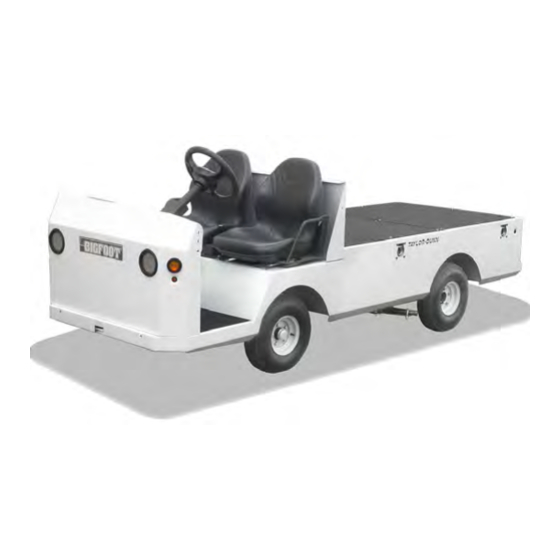
MANUAL: MB-440-10
Bigfoot G-1500
Model Numbers:
B5-440-GAS
T h e B e s t W a y
T o G o
A b o u t Y o u r
B u s i n e s s
WARNING
READ THE OPERATOR'S MANUAL BEFORE OPERATING
THIS VEHICLE.
The operator's manual contains important information
regarding the safe operation of this vehicle.
Starting Serial Number: 204278
Ending Serial Number: See Introduction Chapter
H
Advertisement
Chapters
Table of Contents

Subscribe to Our Youtube Channel
Related Manuals for Taylor-Dunn Bigfoot G-1500


Summary of Contents for Taylor-Dunn Bigfoot G-1500
- Page 1 Service and Replacement Parts Manual MANUAL: MB-440-10 Bigfoot G-1500 Model Numbers: B5-440-GAS T h e B e s t W a y T o G o A b o u t Y o u r B u s i n e s s WARNING READ THE OPERATOR’S MANUAL BEFORE OPERATING...
- Page 2 Service Advisor at your local dealership. Taylor-Dunn has a worldwide dealer and distribution network to provide replacement parts and service for our vehicles. Refer to our web site, www.taylor-dunn.com, for a dealer lookup application. Originally Published 5/1/2017 Revision H, 10/17/2018, contents subject to change without notice ®...
- Page 3 Taylor-Dunn Contact information Service, Parts, Sales: Taylor-Dunn has a network of dealers distributed around the globe to support our vehicles. Information regarding vehicle sales, replacement parts, or service should be obtained through your local dealer. A dealer locator can be found on the Taylor-Dunn website at www.taylor-dunn.com.
- Page 4 Decades of experience are an invaluable asset, and it is an asset we cherish and protect. Our guiding principle is to provide application- specific solutions, which are reliable, efficient, and economical. Our domestic and international network of quality Taylor-Dunn Dealers and Parts & Service Support keeps our customers moving. Tiger Tractor: Tiger manufacturing has become a leading manufacturer of internal combustion industrial tractors and ground support equipment.
-
Page 5: Table Of Contents
Master Table of Contents Note: Each section title page contains a section table of contents Introduction ............7 Service/Maintenance Guidelines....13 Preventative Maintenance ......17 Lubrication ............21 Front Axle ............25 Steering ............33 Engine ...............41 Transaxle ............45 CVT Transmission ...........49 Brakes...............53 Throttle Cables ..........61 Shift Linkage ............63 Tires &... - Page 7 Table of Contents Introduction About this manual ...........8 Who Should Read This Manual ......8 How To Use This Manual ........8 Conventions ............9 Signal Words and Their Definitions: ......9 Responsibilities ..........10 How to Identify Your Vehicle ......11 Web Site Registration ........11 WARNING This section is one section of a complete service manual.
-
Page 8: Introduction
Taylor-Dunn is not to be held liable for errors in this HOW TO USE THIS MANUAL manual or any consequential damage that results from the use of this manual. -
Page 9: Introduction
Introduction Bigfoot G-1500 Conventions Symbols and/or words used to define Dangers, Warnings, Cautions, and Notices are found throughout this manual. The “Words” in this context will be referred to as “Signal words.” The words defined here as “signal words” may be used elsewhere in the text of this document without being a signal word. -
Page 10: Responsibilities
Of the Service Personnel... WARNING The only personnel authorized to repair, modify, or adjust any part of this or any Taylor-Dunn vehicle is a factory authorized service technician. Repairs made by unauthorized personnel may result in damage to the vehicles systems which could lead to an unsafe condition resulting in severe bodily injury and/or property damage. -
Page 11: How To Identify Your Vehicle
WEB SITE REGISTRATION Registering on the Taylor-Dunn web site will give you access to a wealth of information about your vehicle and the entire Taylor- Dunn line of vehicles. Your contact information will remain confidential and will not be shared outside of the Taylor-Dunn corporation. - Page 12 Notes Introduction Bigfoot G-1500 Page-12 MB-440-10...
- Page 13 Table of Contents Service/Maintenance Guidelines READ ME FIRST-Maintenance Guidelines and General instructions .........14 Vehicle Modifications ........15 Replacement Parts ..........16 Using Non-OEM Replacement Components ...16...
-
Page 14: Service/Maintenance Guidelines
WARNING BEFORE STARTING ANY REPAIRS The only personnel authorized to repair, modify, or adjust any part of this or any Taylor-Dunn vehicle is 1) Make sure the ignition switch is in the “OFF” a factory authorized service technician. Repairs made position, then remove the key. -
Page 15: Service/Maintenance Guidelines
Service/Maintenance Guidelines Bigfoot G-1500 VEHICLE MODIFICATIONS Taylor-Dunn vehicles are designed and manufactured in accordance with ANSI/ITSDF and OSHA regulations. Per ANSI/ITSDF and OHSA, modifications to the vehicle must be approved by the manufacturer. Listed below are the specific regulations: ANSI/ITSDF 56.8-2006 Personnel and Burden Carriers Paragraph 8.2q:... -
Page 16: Replacement Parts
To maintain peak performance, always use original Taylor-Dunn replacement parts intended for use on your vehicle. Taylor-Dunn components are designed and tested for use on specific Taylor-Dunn model vehicles. Only use the correct Taylor-Dunn replacement components for your Taylor-Dunn vehicle. - Page 17 Table of Contents Preventative Maintenance Daily Visual Inspection ........18 Pre-Operation Inspection ........18 Maintenance Schedule ........18 Maintenance Guidelines for Severe Duty Applications ....Maintenance Schedule ..........19 WARNING This section is one section of a complete service manual. Before starting any procedure, read all warnings and instructions that are located in the Service Guidelines chapter.
-
Page 18: Daily Visual Inspection
PM Schedule Bigfoot G-1500 DAILY VISUAL INSPECTION PRE-OPERATION INSPECTION WARNING WARNING This section is one section of a complete service This section is one section of a complete service manual. Before starting any procedure, read all manual. Before starting any procedure, read all... -
Page 19: Preventative Maintenance
PM Schedule Bigfoot G-1500 Maintenance Schedule Every 200 hours Most of these items shall only be performed by a qualified • All 100 hour items plus the following: technician. Refer to the vehicle, engine, or transmission • Change oil filter. - Page 20 Notes PM Schedule Bigfoot G-1500 Page 20 MB-440-10...
- Page 21 Table of Contents Lubrication Lubrication and Fluids Chart ......22 Lubrication Diagram ........23 Hazardous Waste Disposal ......23...
- Page 22 Lubrication Bigfoot G-1500 LUBRICATION AND FLUIDS CHART Assembly Component # of Locations Capacity Lubricant Front Axle: 3: Wheel Bearings NLGI Grade 2 lithium high temp Bearing Grease 4: King Pin NLGI Grade 2 lithium multi-purpose grease Suspension: Steering: 1: Steering Rack NLGI Grade 2 lithium multi-purpose grease 2: 90°...
-
Page 23: Lubrication
Lubrication Bigfoot G-1500 LUBRICATION DIAGRAM Drive Axle Front Axle / Steering HAZARDOUS WASTE DISPOSAL This vehicle contains various components and/or fluids that may be classified as hazardous waste. This includes but is not limited to Lead, Acid, Oil, Grease. The brake linings originally installed by the factory do not contain asbestos. However, since it is possible that asbestos brake linings were installed as replacement parts, brake linings should be handled as hazardous waste. - Page 24 Notes Lubrication Bigfoot G-1500 Page 24 MB-440-10...
- Page 25 Table of Contents Front Axle Remove.............26 Install ..............26 Assemble Complete Axle ........27 Inspect Front Wheel Bearings ......28 Adjust Front Wheel Bearings ......28 Front Wheel Alignment ........29 Replace Steering Knuckle ......30 Replace King Pin/Bushings ......31 Replace Front Wheel Bearings.......31 Service Limits and Specifications ....32 King Pin Bushings ...........32 Toe In ...............32 Hardware Torque ..........32...
-
Page 26: Front Axle
Front Axle Bigfoot G-1500 REMOVE WARNING NOTICE This section is one section of a complete service manual. Before starting any procedure, read all If vehicle is equipped with front brakes, you will warnings and instructions that are located in the need to disconnect the front brakes and bleed the Service Guidelines chapter. -
Page 27: Front Axle
Front Axle Bigfoot G-1500 ASSEMBLE COMPLETE AXLE WARNING This section is one section of a complete service manual. Before starting any procedure, read all warnings and instructions that are located in the Service Guidelines chapter. Note: Thrust bearings should be packed with grease before assembly. -
Page 28: Inspect Front Wheel Bearings
Front Axle Bigfoot G-1500 INSPECT FRONT WHEEL ADJUST FRONT WHEEL BEARINGS WARNING BEARINGS WARNING This section is one section of a complete service manual. Before starting any procedure, read all This section is one section of a complete service warnings and instructions that are located in the manual. -
Page 29: Front Wheel Alignment
Front Axle Bigfoot G-1500 FRONT WHEEL ALIGNMENT WARNING This section is one section of a complete service manual. Before starting any procedure, read all warnings and instructions that are located in the Service Guidelines chapter. Note: Only Toe In can be set. Both Caster and Camber are not adjustable. -
Page 30: Replace Steering Knuckle
Front Axle Bigfoot G-1500 REPLACE STEERING KNUCKLE WARNING This section is one section of a complete service manual. Before starting any procedure, read all warnings and instructions that are located in the Service Guidelines chapter. Remove 1: Raise the front of the vehicle and support with jack stands. -
Page 31: Replace King Pin/Bushings
Front Axle Bigfoot G-1500 REPLACE KING PIN/BUSHINGS REPLACE FRONT WHEEL WARNING BEARINGS WARNING This section is one section of a complete service manual. Before starting any procedure, read all This section is one section of a complete service warnings and instructions that are located in the manual. -
Page 32: Service Limits And Specifications
Front Axle Bigfoot G-1500 SERVICE LIMITS AND SPECIFICATIONS HARDWARE TORQUE Description Foot Pounds Newton Meters King Pin Bushings Ball Joint Lock Nut 43-47 58-63 Ream or broach to 0.8755-0.08765 inches Steering link Jam Nut 20-30 27-40 (22.2377-22.2631 mm) Steering pinch bolt... - Page 33 Table of Contents Steering Inspect Ball Joints ...........34 Front Wheel Alignment ........34 Replace Ball Joint..........34 Replace Upper Steering Shaft ......35 Remove ..............35 Install ...............35 Replace Lower Steering Shaft ......36 Inspect ..............36 Remove ..............36 Install ...............36 Replace Boot ............36 Replace 90° Steering Gear ......37 Inspect ..............37 Remove ..............37 Install ...............37...
-
Page 34: Inspect Ball Joints
Steering Bigfoot G-1500 INSPECT BALL JOINTS REPLACE BALL JOINT WARNING WARNING This section is one section of a complete service This section is one section of a complete service manual. Before starting any procedure, read all manual. Before starting any procedure, read all... -
Page 35: Steering
Steering Bigfoot G-1500 REPLACE UPPER STEERING SHAFT WARNING WARNING This section is one section of a complete service Do not use the original pinch bolt and nut. Failure to manual. Before starting any procedure, read all replace the pinch bolt and nut may result in failure of warnings and instructions that are located in the the steering causing loss of control of the vehicle. -
Page 36: Replace Lower Steering Shaft
Steering Bigfoot G-1500 REPLACE LOWER STEERING SHAFT WARNING Install 1: Thoroughly clean the couplers and shafts. This section is one section of a complete service 2: Position the front wheels in the straight ahead manual. Before starting any procedure, read all position. -
Page 37: Replace 90° Steering Gear
Steering Bigfoot G-1500 REPLACE 90° STEERING GEAR WARNING This section is one section of a complete service manual. Before starting any procedure, read all warnings and instructions that are located in the Service Guidelines chapter. There are no internal components available for the 90° steering gear. If worn out it must be replaced. -
Page 38: Replace Steering Rack
Steering Bigfoot G-1500 REPLACE STEERING RACK WARNING This section is one section of a complete service manual. Before starting any procedure, read all warnings and instructions that are located in the Service Guidelines chapter. There are no internal components available for the steering rack. If worn out it must be replaced. -
Page 39: Replace Steering Wheel
Steering Bigfoot G-1500 REPLACE STEERING WHEEL WARNING This section is one section of a complete service manual. Before starting any procedure, read all warnings and instructions that are located in the Service Guidelines chapter. Note: The steering wheel is on a tapered shaft and may be damaged when it is removed. -
Page 40: Hardware Torque
Steering Bigfoot G-1500 HARDWARE TORQUE Description Foot Pounds Newton Meters Ball Joint Jam Nut 20-30 27-40 Ball Joint Lock Nut 43-47 58-63 Notes Coupler Pinch Bolt 30-35 40-47 Coupler Pinch Bolt Jam Nut 25-30 34-40 Steering Wheel Nut 28-32 38-43... - Page 41 Table of Contents Engine Check Oil Level ..........42 Change Oil ............42 Air Filter Service ..........43 Spark Plug Service ..........43 Only basic engine maintenance information is included in this manual. For engine repair refer to the complete Kohler en- gine service manual that can be downloaded from the Kohler web site at www.kohlerengines.com The model number of the engine will be required...
- Page 42 Refer to Oil Type and Capacities on this page 1: Park the vehicle on a level surface. Taylor-Dunn does not recommend the use of oil additives. 2: The engine should be warm. Before checking engine oil level: Turn engine off and wait 3: Place an oil drain pan underneath the drain a couple of minutes to allow oil to return to the crankcase.
-
Page 43: Engine
Engine Bigfoot G-1500 AIR FILTER SERVICE SPARK PLUG SERVICE WARNING WARNING This section is one section of a complete service This section is one section of a complete service manual. Before starting any procedure, read all manual. Before starting any procedure, read all... - Page 44 Notes Engine Bigfoot G-1500 Page 44 MB-440-10...
- Page 45 Table of Contents Transaxle Disassemble.............46 Assemble............47 Differential ............48 Axle Shaft ............48 Remove ..............48 Install ...............48 Replace Axle Bearing ..........48 WARNING This section is one section of a complete service manual. Before starting any procedure, read all warnings and instructions that are located in the Service Guidelines chapter.
-
Page 46: Disassemble
Transmission Bigfoot G-1500 DISASSEMBLE WARNING This section is one section of a complete service manual. Before starting any procedure, read all warnings and instructions that are located in the Service Guidelines chapter. Notes: The brakes and axle shafts DO NOT need to be removed from the axle tube unless the axle or brakes require servicing. -
Page 47: Transaxle
Transmission Bigfoot G-1500 ASSEMBLE WARNING This section is one section of a complete service manual. Before starting any procedure, read all warnings and instructions that are located in the Service Guidelines chapter. • Thoroughly clean all components and cases. • Inspect all components for indications of wear or damage and replace as needed. -
Page 48: Differential
Transmission Bigfoot G-1500 DIFFERENTIAL WARNING This section is one section of a complete service manual. Before starting any procedure, read all warnings and instructions that are located in the Service Guidelines chapter. Note: All hardware and bearings must be replaced if they are removed from the differential /ring gear assembly. - Page 49 Table of Contents CVT Transmission Operation ............50 Driver Pulley.............51 Remove ..............51 Install ...............51 Driven Pulley ............51 Remove ..............51 Inspect ..............51 Install ...............51 Repair ..............51 Drive Belt ............52 Remove ..............52 Inspect ..............52 Install ...............52 WARNING This section is one section of a complete service manual.
- Page 50 Bigfoot G-1500 OPERATION WARNING This section is one section of a complete service manual. Before starting any procedure, read all warnings and instructions that are located in the Service Guidelines chapter. A CVT is a Continuously Variable Transmission and functions to keep the engine RPM constant in the area of maximum torque and/or efficiency.
-
Page 51: Cvt Transmission
Bigfoot G-1500 DRIVER PULLEY WARNING This section is one section of a complete service manual. Before starting any procedure, read all warnings and instructions that are located in the Service Guidelines chapter. The driver pulley has no serviceable components. If not functioning correctly then it must be replaced as an assembly. - Page 52 Bigfoot G-1500 DRIVE BELT WARNING This section is one section of a complete service manual. Before starting any procedure, read all warnings and instructions that are located in the Service Guidelines chapter and beginning of this section.. Note: The ramp shoes should be inspected any time the belt is serviced.
- Page 53 Table of Contents Brakes General Guidelines and Safety.......54 Front Disc Brake ..........55 Service Limits ............55 Inspection ..............55 Replace Pads ............55 Brake Adjustment ..........56 Service Brake ............56 Parking Brake ............56 Master Cylinder..........56 Add Fluid ..............56 Push Rod Adjustment ..........56 Rear Brake, Inspect/Replace ......57 Service Limits ............57 Inspection ..............57 Replace ..............57...
-
Page 54: General Guidelines And Safety
Bigfoot G-1500 GENERAL GUIDELINES AND SAFETY WARNING WARNING Taylor-Dunn does not currently supply asbestos This section is one section of a complete service fiber-brake pads/shoes with any vehicle. However, manual. Before starting any procedure, read all there is the possibility that the original brake pads/... -
Page 55: Brakes
Brakes Bigfoot G-1500 FRONT DISC BRAKE WARNING This section is one section of a complete service manual. Before starting any procedure, read all warnings and instructions that are located in the Service Guidelines chapter. Service Limits Refer to the table at the end of this section... -
Page 56: Brake Adjustment
Brakes Bigfoot G-1500 BRAKE ADJUSTMENT MASTER CYLINDER WARNING WARNING This section is one section of a complete service This section is one section of a complete service manual. Before starting any procedure, read all manual. Before starting any procedure, read all... -
Page 57: Rear Brake, Inspect/Replace
Brakes Bigfoot G-1500 Replace REAR BRAKE, INSPECT/REPLACE 1: Release the park brake. WARNING 2: Raise the rear wheels off of the ground and support with jack stands. 3: Remove the tire/wheel assembly. Refer to This section is one section of a complete service Tires manual. -
Page 58: Rebuild Disc Brake Body
Brakes Bigfoot G-1500 REBUILD DISC BRAKE BODY WARNING This section is one section of a complete service manual. Before starting any procedure, read all warnings and instructions that are located in the Service Guidelines chapter. This procedure assumes that the component has been removed from the vehicle. -
Page 59: Bleed System
Brakes Bigfoot G-1500 FLUSH SYSTEM BLEED SYSTEM 1: Raise the rear wheels off of the ground and WARNING support with jack stands. 2: If equipped with front brakes, raise the front wheels off of the ground and support with jack This section is one section of a complete service stands. -
Page 60: Service Limits
Brakes Bigfoot G-1500 HARDWARE TORQUE SERVICE LIMITS Description Imperial Metric If hardware is not listed here, refer to standard torque values in the appendix. Disc pad lining minimum thickness 00625 inch 1.58 mm Description Foot Pounds Newton Meters Front rotor minimum thickness 0.200 inch... - Page 61 Table of Contents Throttle Cables Adjust, Throttle / Choke ........62 WARNING This section is one section of a complete service manual. Before starting any procedure, read all warnings and instructions that are located in the Service Guidelines chapter.
- Page 62 Batteries Bigfoot G-1500 ADJUST, THROTTLE / CHOKE WARNING This section is one section of a complete service manual. Before starting any procedure, read all warnings and instructions that are located in the Service Guidelines chapter. NOTICE The maximum engine RPM is controlled by the engine governor.
-
Page 63: Throttle Cables
Table of Contents Shift Linkage Adjustment ............64 WARNING This section is one section of a complete service manual. Before starting any procedure, read all warnings and instructions that are located in the Service Guidelines chapter. - Page 64 Batteries Bigfoot G-1500 ADJUSTMENT WARNING This section is one section of a complete service manual. Before starting any procedure, read all warnings and instructions that are located in the Service Guidelines chapter. NOTICE Do not modify the stainless steel shift cable mounting plate at the transmission.
-
Page 65: Shift Linkage
Table of Contents Tires & Wheels Inflation .............66 Air pressure .............66 Tread Wear ............67 Rotation ............67 Changing Tire/Wheel Assembly .....68 Replace the Tire (pneumatic) ......68 Repair the Tire (pneumatic) ......68 Hardware Torque ..........69 WARNING This section is one section of a complete service manual. -
Page 66: Tires & Wheels
Tires & Wheels Bigfoot G-1500 INFLATION WARNING WARNING Incorrect tire inflation can result in sudden failure of This section is one section of a complete service the tire and/or braking / steering problems leading manual. Before starting any procedure, read all to loss of control of the vehicle. -
Page 67: Tires & Wheels
Tires & Wheels Bigfoot G-1500 TREAD WEAR WARNING WARNING This section is one section of a complete service DO NOT operate a vehicle if the cord is manual. Before starting any procedure, read all visible on any tire (see illustration). A tire... -
Page 68: Changing Tire/Wheel Assembly
Tires & Wheels Bigfoot G-1500 CHANGING TIRE/WHEEL REPLACE THE TIRE (PNEUMATIC) WARNING ASSEMBLY WARNING This section is one section of a complete service manual. Before starting any procedure, read all warnings and instructions that are located in the This section is one section of a complete service Service Guidelines chapter. -
Page 69: Hardware Torque
Tires & Wheels Bigfoot G-1500 HARDWARE TORQUE If hardware is not listed here, refer to standard torque values in the appendix. Description Foot Pounds Newton Meters Wheel nut MB-440-10 Page 69... - Page 70 Notes Tires & Wheels Bigfoot G-1500 Page 70 MB-440-10...
- Page 71 Table of Contents Suspension Front Springs ...........72 Remove ..............72 Install ...............72 Rear Springs ............72 Remove ..............72 Install ...............72 WARNING This section is one section of a complete service manual. Before starting any procedure, read all warnings and instructions that are located in the Service Guidelines chapter.
- Page 72 Suspension Bigfoot G-1500 FRONT SPRINGS REAR SPRINGS WARNING Remove WARNING This section is one section of a complete service manual. Before starting any procedure, read all DO NOT attempt to remove the springs until the warnings and instructions that are located in the vehicle is firmly supported on jack stands.
-
Page 73: Suspension
Table of Contents Battery General Guidelines and Safety.......74 Cleaning ............75 Watering ............75 Testing ..............76 Specific Gravity ............76 Storing ..............76 Storage ..............76 Returning to Service ..........76 Remove/Install ..........77 Hardware Torque ..........78 WARNING This section is one section of a complete service manual. -
Page 74: General Guidelines And Safety
Batteries Bigfoot G-1500 GENERAL GUIDELINES AND SAFETY WARNING NOTICE Battery electrolyte will stain and corrode most This section is one section of a complete service surfaces. Immediately and thoroughly clean any manual. Before starting any procedure, read all surface outside of the battery that the battery warnings and instructions that are located in the electrolyte comes in contact with. -
Page 75: Battery
Batteries Bigfoot G-1500 CLEANING WATERING WARNING WARNING This section is one section of a complete service This section is one section of a complete service manual. Before starting any procedure, read all manual. Before starting any procedure, read all warnings and instructions that are located in the... -
Page 76: Testing
Batteries Bigfoot G-1500 TESTING STORING WARNING WARNING This section is one section of a complete service This section is one section of a complete service manual. Before starting any procedure, read all manual. Before starting any procedure, read all warnings and instructions that are located in the... -
Page 77: Remove/Install
Batteries Bigfoot G-1500 REMOVE/INSTALL WARNING This section is one section of a complete service manual. Before starting any procedure, read all warnings and instructions that are located in the Service Guidelines chapter and beginning of this section.. 1: Turn the engine off and set the park brake. -
Page 78: Hardware Torque
Batteries Bigfoot G-1500 HARDWARE TORQUE If hardware is not listed here, refer to standard torque values in the appendix. Description Inch Pounds Newton Meters Battery terminal, Clamp 48-60 5.4-6.7 Battery terminal, Stud 120-130 13.5-14.5 Page 78 MB-440-10... - Page 79 The wire diagram for this vehicle is included on the Vehicle Documentation CD provided with the vehicle. The diagram #’s for this vehicle are: SCH-00105 This vehicle diagram as well as other Taylor-Dunn vehicle diagrams can be downloaded from the Taylor-Dunn web site at www.taylor-dunn.com.
- Page 80 Wire Diagram Bigfoot G-1500 DIAGRAM BATT Green Blue Page 80 Bigfoot G-1500...
-
Page 81: Wire Diagram
Table of Contents Hardware Information Torque Guidelines for Standard hardware ..82 Hardware Identification ..........82 Hex Nuts ..............83 Hex Lock Nuts (stover) ..........83 Other Nuts ...............83 Generic Torque Values ..........84 Replacing Hardware ........86 WARNING This section is one section of a complete service manual. -
Page 82: Torque Guidelines For Standard Hardware
Hardware Bigfoot G-1500 TORQUE GUIDELINES FOR STANDARD HARDWARE Note: Torque values specified are for clean dry threads. Note: Torque value used should be for lowest grade of hardware used. If a grade 2 nut is used on a grade 8 bolt, use grade 2 torque value. -
Page 83: Hardware Information
‘2’ hex nuts, Grade ‘B’ as Grade ‘5’ and Grade ‘C’ as Grade ‘8’. NOTE: Nuts with no markings are to be treated as S.A.E. Grade A S.A.E. Grade B S.A.E. Grade C Grade L’9 Other Nuts Other nuts used by Taylor-Dunn ® should be treated as S.A.E. grade A MB-440-10 Page 83... -
Page 84: Generic Torque Values
Hardware Bigfoot G-1500 Generic Torque Values All torque values are for clean dry zinc plated threads in noncritical steel assemblies of the same hardness specification. Reduce torque approximately 10-15% for lubricated threads. Refer to the service section assembly procedure for critical torque values. - Page 85 Hardware Bigfoot G-1500 All torque values are for clean dry zinc plated threads in noncritical steel assemblies of the same hardess specification. Reduce torque approximately 10-15% for lubricated threads. Refer to the service section assembly procedure for critical torque values.
-
Page 86: Replacing Hardware
Hardware Bigfoot G-1500 REPLACING HARDWARE WARNING This section is one section of a complete service manual. Before starting any procedure, read all warnings and instructions that are located in the Service Guidelines chapter. WARNING Failure to follow the following guidelines may result in failure of the hardware resulting in severe bodily injury or property damage: •... - Page 87 TABLE OF CONTENTS Replacement Parts Ordering Parts for Your Vehicle .....88 Taylor-Dunn Web Site Information ....88 Axle Assembly, Front ........90 Axle Assembly, Rear ........92 Brakes, Brake Lines ........94 Brakes, Front Axle ...........96 Brakes, Rear Axle ..........97 Decals ...............98 Electrical, Miscellaneous ........100 Engine / Exhaust..........102...
-
Page 88: Replacement Parts
ORDERING PARTS FOR YOUR VEHICLE WARNING The only personnel authorized to repair, modify, or adjust any part of this or any Taylor-Dunn vehicle is a factory authorized service technician. Repairs made by unauthorized personnel may result in damage to the vehicles systems which could lead to an unsafe condition resulting in severe bodily injury and/or property damage. -
Page 89: Replacement Parts
Replacement Parts Bigfoot G-1500 My Vehicle information Serial Number: Date Purchased: Date Delivered: Dealer Purchased From: Salesman Name: Notes My local Parts Dealer: MB-440-10 * Not available at time of printing Page 89... -
Page 90: Axle Assembly, Front
Replacement Parts Bigfoot G-1500 AXLE ASSEMBLY, FRONT Page 90 MB-440-10... - Page 91 Replacement Parts Bigfoot G-1500 Axle Assembly, Front Item No. Part No. Description 12-115-15 Hub (includes 4, 6) 92-105-00 Dust Cap 80-011-10 Bearing 80-102-00 Race 80-011-10 Bearing 80-102-00 Race 45-307-00 Seal 14-010-19 Steering Knuckle, Right 14-010-20 Steering Knuckle, Left 9 / 10...
-
Page 92: Axle Assembly, Rear
Replacement Parts Bigfoot G-1500 AXLE ASSEMBLY, REAR Item No. Part No. Description 4C-610-40 Axle Assembly, Complete (012AJ389-1) Housing, w/idler shaft Case 66-610-82 Detent kit 66-610-29 Seal 66-611-20 Shift actuator assembly 66-611-19 Shift rod assembly 45-303-30 Seal 66-610-75 Axle tube 66-610-76... - Page 93 Replacement Parts Bigfoot G-1500 Item No. Part No. Description 41-516-00 Brake drum 66-610-65 Flange head screw 66-610-69 Lock nut 66-610-59 Rubber plug Vent Dowel pin 80-480-02 Bearing Input shaft 66-610-88 Shim kit 66-610-35 Bearing 80-480-01 Bearing Spacer Shim Thrust washer...
-
Page 94: Brakes, Brake Lines
Replacement Parts Bigfoot G-1500 BRAKES, BRAKE LINES Page 94 MB-440-10... - Page 95 Replacement Parts Bigfoot G-1500 Brake Lines Item No. Part No. Description 99-607-12 Brake Line 99-607-14 Brake Line 99-607-13 Brake Line 99-601-10 Brake Line 99-606-51 Brake Line 99-605-84 Brake Line 99-605-83 Brake Line 99-606-05 Brake Line 99-606-06 Brake Line 99-559-00 T-Fitting...
-
Page 96: Brakes, Front Axle
Replacement Parts Bigfoot G-1500 BRAKES, FRONT AXLE Item No. Part No. Description 41-351-35 Complete Brake Assembly 88-067-29 Bolt 41-350-91 Plate, Secondary 41-348-58 Spacer 32-208-01 Bushing (included in rebuild kit) Brake Body (all parts on this list) 99-588-01 Bleeder adaptor 99-588-00... -
Page 97: Brakes, Rear Axle
Replacement Parts Bigfoot G-1500 BRAKES, REAR AXLE Item No. Part No. Description 41-347-15 Parking Brake Actuator 41-347-00 Backing Plate 41-347-36 Spider, w/Wheel Cylinder 85-411-10 Torsion Spring 41-635-00 Brake Shoes 85-215-00 Spring 41-347-33 Adjustment Body 41-347-31 Star Wheel Adjuster 41-347-30 Socket... -
Page 98: Decals
Replacement Parts Bigfoot G-1500 DECALS Page 98 MB-440-10... - Page 99 Replacement Parts Bigfoot G-1500 Decals Item No. Part No. Description 94-301-41 DOT 3 BRAKE FLUID 94-301-42 ARMS/LEGS 94-301-65 BIGFOOT 94-306-01 FUEL/OIL CHECK 94-306-02 SPEED WARNING 94-306-03 HEAT WARNING 94-306-04 ROTATING PARTS WARNING 94-306-05 OIL TYPE 94-306-06 DIPSTICK WARNING 94-306-07 PUSH TO SHIFT...
-
Page 100: Electrical, Miscellaneous
Replacement Parts Bigfoot G-1500 ELECTRICAL, MISCELLANEOUS Page 100 MB-440-10... - Page 101 Replacement Parts Bigfoot G-1500 Electrical Item No. Part No. Description 96-624-00 Clamp, 1/4 Jiffy Clip 96-625-00 Clamp, 5/16 Jiffy Clip 96-626-00 Clamp, 7/8 Jiffy Clip 96-640-00 Clamp, 3/16 Push Mount 96-642-00 Wire harness Clip, push mount 96-650-01 Wire Harness Clip, stick on...
-
Page 102: Engine / Exhaust
Replacement Parts Bigfoot G-1500 ENGINE / EXHAUST Item No. Part No. Description 67-000-53-16 Engine Assembly, 2016 year model (S/N 204278 only) 0 or 1 67-000-53-17 Engine Assembly, 2017 year model (after S/N 204278) 0 or 1 67-000-53-18 Engine Assembly, 2017 year model (after S/N 209616) -
Page 103: Frame And Body (Cabs)
Replacement Parts Bigfoot G-1500 FRAME AND BODY (CABS) Economy Cab Item No. Part No. Description 00-500-15 Cab (unpainted) 90-852-30 Windshield 98-310-00 Gasket per foot 90-850-10 Rear window 98-310-00 Gasket per foot 90-924-90 Door Frame, Left 90-924-91 Door, Frame Right 90-923-30... -
Page 104: Frame, Deck
Replacement Parts Bigfoot G-1500 FRAME, DECK Deck Item No. Part No. Description 90-472-03 Deckboard, Rear 90-471-02 Deckboard, Front 90-441-37 Steel cover, Black, Rear 90-441-36 Steel cover, Black, Front 88-607-09 Rivet 05-210-90 Heat shield, Rear deck 05-210-94 Heat shield, Front deck... -
Page 105: Hitches
Replacement Parts Bigfoot G-1500 HITCHES Mounting Hardware Item No. Part No. Description 97-811-00 1-7/8 inch Ball 97-821-00 2-inch Ball 88-140-14 1/2NC x 1-1/2 Hex bolt 88-149-80 1/2NC Hex nut 88-148-62 1/2 Split lock washer MB-440-10 * Not available at time of printing... -
Page 106: Instrument Panel
Replacement Parts Bigfoot G-1500 INSTRUMENT PANEL Instrument Panel Item No. Part No. Description 71-120-01 Switch, Ignition 71-120-80 Key (PK556) 74-009-20 Fuel Gauge 74-000-00 Hour Meter 71-039-11 Switch, Lights 71-039-11 Switch, Wiper 0 or 1 71-039-11 Switch, Strobe Light 0 or 1... -
Page 107: Linkage, Park Brake
Replacement Parts Bigfoot G-1500 LINKAGE, PARK BRAKE Item No. Part No. Description 51-340-30 Handle, park Brake 96-813-00 Cable, Park Brake (handle to equalizer) 96-826-12 Cable, Park Brake (equalizer to brake) 96-826-09 Cable lock 88-847-08 Retaining ring 85-126-00 Spring, Compression, 3 inch... -
Page 108: Linkage, Throttle
Replacement Parts Bigfoot G-1500 LINKAGE, THROTTLE Item No. Part No. Description 62-033-25 Mounting bracket 85-352-34 Spring, Pedal Torsion 62-033-18 Bushing 96-860-01 Cable, Choke 00-640-61 Pedal, Throttle 32-215-50 Bushing 85-209-09 Spring, Pedal Extension 96-872-08 Cable. Throttle 88-060-11 Bolt 88-069-81 88-068-61 Washer... -
Page 109: Seats
Replacement Parts Bigfoot G-1500 SEATS Seats Item No. Part No. Description 90-160-96 Seat assembly 90-160-97 Hip restraint, Driver 90-160-98 Hip restraint, Passenger 88-088-61 Flat washer 88-089-81 Lock nut 94-430-07 Thread Lock (50ml) 90-160-95 Operator presence switch (driver seat only) MB-440-10... -
Page 110: Steering Linkage
Replacement Parts Bigfoot G-1500 STEERING LINKAGE Page 110 MB-440-10... - Page 111 Replacement Parts Bigfoot G-1500 Steering Linkage Item No. Part No. Description 19-011-30 Steering Wheel 19-011-35 Steering Wheel Cover 88-199-82 5/8 NF Hex Head Jam Nut GR 2 18-058-92 Steering Shaft Assembly 32-248-20 Steering Bushing 89-080035K-C-00 Bolt 89-0800000-A-07 M8, Lock Washer,Split Ring 89-080000K-C-04 M8x1.25 Metal Locknut, 10.9...
-
Page 112: Suspension, Front
Replacement Parts Bigfoot G-1500 SUSPENSION, FRONT Front Suspension Item No. Part No. Description 96-240-00 Spring Bolt 32-214-50 Bushing 16-871-04 Spring Hanger 88-149-81 1/2 NC LOCK NUT GR5 85-498-00T Leaf Spring 14-010-07 Spring plate Not Shown 98-753-15 Bump Stop 86-602-01 Shock (optional) -
Page 113: Suspension, Rear
Replacement Parts Bigfoot G-1500 SUSPENSION, REAR Item No. Part No. Description 86-602-01 Shock 85-142-00 Spring 86-521-98 Rod end, LH 86-521-99 Rod end, RH 86-523-99 Rod end (front swing arm mount) 88-120-17 Bolt 88-129-81 88-121-19 Bolt 88-121-19 Bolt 88-188-61 Flat washer... -
Page 114: Transmission, Cvt
Replacement Parts Bigfoot G-1500 TRANSMISSION, CVT Item No. Part No. Description 30-181-00 Pulley, Engine 97-030-20 88-111-22 Bolt 88-128-62 Lock washer 88-159-61 Flat washer, Heavy 30-182-00 Pulley, Drive axle 97-030-10 30-180-51 Ramp shoe (plastic) 98-601-51 Flat washer, 1/2 88-148-62 Lock washer... -
Page 115: Wheels And Tires
Replacement Parts Bigfoot G-1500 WHEELS AND TIRES Item No. Part No. Description 13-742-13 Tire/Wheel assembly, 5.70 x 8 LRC 10-083-00 Tire, 5.70 x 8 LRC 11-040-00 Tube 97-236-00 Wheel Nut 13-989-00 Valve stem, tubeless tire only MB-440-10 * Not available at time of printing... - Page 116 Notes: Replacement Parts Bigfoot G-1500 Page 116 MB-440-10...
- Page 117 WARNING Operating, servicing and maintaining a passenger vehicle or off- highway motor vehicle can expose you to chemicals including engine exhaust, carbon monoxide, phthalates, and lead, which are known to the State of California to cause cancer and birth defects or other reproductive harm.
- Page 118 Taylor-Dunn® Manufacturing. 2114 West Ball Road. Anaheim, CA 92804 (800)-688-8680 (714) 956-4040 FAX: (714) 956-0504 Visit our Website: www.taylor-dunn.com...
Need help?
Do you have a question about the Bigfoot G-1500 and is the answer not in the manual?
Questions and answers