Table of Contents
Advertisement
Quick Links
Operator's Manual
WARNING
READ THIS MANUAL BEFORE OPERATION
OR PERFORMING MAINTENANCE.
This manual contains important information
regarding the safe operation and maintenance of
this vehicle. This manual should be kept with the
vehicle.
D
The best way to go about your business
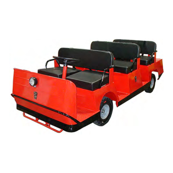
BT-280 Tram
Use with Model Numbers:
BT-280-36 (36 volt)
BT-280-48 (48-volt)
Serial Number Range:
Starting: 205963
Ending: See Introduction Chapter
MB-280-02
Advertisement
Table of Contents

Subscribe to Our Youtube Channel
Related Manuals for Taylor-Dunn BT-280 Series


Summary of Contents for Taylor-Dunn BT-280 Series
- Page 1 The best way to go about your business Operator’s Manual BT-280 Tram Use with Model Numbers: BT-280-36 (36 volt) BT-280-48 (48-volt) WARNING READ THIS MANUAL BEFORE OPERATION Serial Number Range: OR PERFORMING MAINTENANCE. Starting: 205963 This manual contains important information Ending: See Introduction Chapter regarding the safe operation and maintenance of this vehicle.
- Page 2 Representative or Service Advisor at your local dealership. Taylor-Dunn has a worldwide dealer and distribution network to provide replacement parts and service for our vehicles. Refer to our web site, www.taylor-dunn.com, for a dealer lookup application. Originally Published: 12/14/2017 Revision D, 8/13/2018...
- Page 3 Taylor-Dunn Contact Information Service, Parts, Sales: Taylor-Dunn has a network of dealers distributed around the globe to support our vehicles. Information regarding vehicle sales, replacement parts, or service should be obtained through your local dealer. A dealer locator can be found on the Taylor-Dunn website at www.taylor-dunn.com.
-
Page 4: The Taylor-Dunn Corporation
As with all Taylor-Dunn vehicles; quality, service, support and reliability are built into all Tiger Tractor products. Shown below is just a small sample of what Taylor-Dunn has to offer to keep your business moving:... -
Page 5: Table Of Contents
Table of Contents The Taylor-Dunn Corporation: ..4 Parking Brake, Automatic ..... 18 Seat Adjustment ........18 Introduction Seat Interlock Switch ......19 Park Brake ........... 19 Who Should Read This Manual ... 7 Charger Interlock ......... 19 About This Manual ....... 7 Trailer Brake Module ...... - Page 6 Vehicle Maintenance Daily Inspection ........41 Pre-Operation Inspection ..... 41 Interlock Switch Inspection ...42 Start Switch ......... 42 Operator Presence Switch ....42 Parking Brake Switch: ......42 Brake Interlock Switch ......43 Charger Interlock Switch ...... 43 Maintenance Schedule ......44 Maintenance Guidelines for Severe Duty Applications ..........
-
Page 7: Introduction
Taylor-Dunn web site. A place to record your vehicle information is provided on the inside front cover This manual is subject to change without notice. Updates are available through your dealer or the Taylor-Dunn web site at www.taylor-dunn.com. -
Page 8: Glossary Of Terms
MB-280-02 GLOSSARY OF TERMS There are a number of words and phrases used in this document that may have a different, special, or specific definition when use in the context of this document. A p p r o v e d O p e r a t o r The operator shall be seated in the operator seat with back up against Position the operator seat back cushion. -
Page 9: Web Site Registration
Warning (signal word): WEB SITE REGISTRATION Registering on the Taylor-Dunn web site will give you access to a wealth of information about your vehicle and the entire Taylor- Dunn line of vehicles. Your contact information will remain confidential and will not be shared outside of the Taylor-Dunn corporation. -
Page 10: Responsibilities
RESPONSIBILITIES Of the Owner... The owner of this or any Taylor-Dunn vehicle is responsible for the overall maintenance and repairs of the vehicle, as well as the training of operators. The owner is responsible for operator training. Refer to Driver Training section for details. -
Page 11: Conventions
MB-280-02 CONVENTIONS Symbols and/or words used to define Dangers, Warnings, Cautions, and Notices are found throughout this manual. The “Words” in this context will be referred to as “Signal words.” The words defined here as “signal words” may be used elsewhere in the text of this document without being a signal word. -
Page 12: Vehicle Modifications
Contact the factory for information regarding available alternate program settings. Taylor-Dunn will only authorize the use of settings obtained from the factory for a specific vehicle. Any other alterations to the programming ARE NOT AUTHORIZED and is at your own risk. -
Page 13: About Your Vehicle
MB-280-02 About Your Vehicle The purchase of your Taylor-Dunn vehicle shows a belief in high quality products manufactured in the USA. Your new vehicle operates entirely on electric battery power. It is an emissions free vehicle. Taylor-Dunn, a leading manufacturer of electric burden and personnel carriers since 1949, wants to be sure this vehicle provides years of reliable service. -
Page 14: How To Identify Your Vehicle
MB-280-02 HOW TO IDENTIFY YOUR VEHICLE Data Plate The vehicle data plate includes information about your vehicle and is located as shown in the illustration below: Frame Serial Number The serial number is also attached to the frame located as shown in the illustration below: Operator Manual Page 14... -
Page 15: Taking Delivery Of Your Vehicle
Immediately contact your dealer and report the problem. The report must be made within 24 hours of receiving the vehicle and its accessories. The only personnel authorized to repair, modify, or adjust any part of this or any Taylor-Dunn vehicle is a factory authorized service technician. -
Page 16: Operator Training
• Understand all safety rules and guidelines as presented in this manual. • Know how to properly load and unload cargo. • Know how to properly park this vehicle. • Recognize an improperly maintained vehicle. • Demonstrate the ability to handle this vehicle in all conditions. www.taylor-dunn.com Operator Manual Page 16... -
Page 17: Vehicle Controls
MB-280-02 Vehicle Controls DASH Note: Your vehicle may not include all switches identified. Some of the switches in photo are optional. 1) Headlight Switch 6) Smart View Display Push the top of the switch to turn the lights The gauge on the dash has many functions. on. Push the bottom of the switch to turn the Detailed operation is provided later in this lights off. -
Page 18: Parking Brake, Automatic
MB-280-02 WARNING The park brake should be disabled for servicing or towing procedures only. Do not operate the vehicle while the automatic park brake is disabled. Operating the vehicle with the automatic park brake disabled could lead to severe bodily injury and/or property damage. -
Page 19: Seat Interlock Switch
MB-280-02 Seat Interlock Switch A switch located under the driver’s seat disables the power to the vehicle when the driver leaves the seat. The driver must be seated for the vehicle to operate. Whenever the driver leaves the vehicle, the driver should turn the key-switch off, place the forward-off-reverse switch in the center “OFF”... -
Page 20: Trailer Brake Module
MB-280-02 Trailer Brake Module (Optional) The trailer brake module controls the braking functions of a trailer equipped with electric brakes. There have been many styles of brake modules used. All of the brake modules that have been used function the same. However, the location of the manual adjustment controls may vary. The brake module will be located under the dash tray to the left of the steering column. -
Page 21: Smart View Display
MB-280-02 Smart View Display The Smart View Display (SVD) functions as a Battery Status Indicator (BSI), Hour Meter (HM), speed controller status monitor, and as an optional maintenance monitor feature. The operation of each of these functions is described below. BSI: A bar graph representing the current state Depending on the revision level of the... - Page 22 MB-280-02 System Fault Monitor The display will indicate a fault code whenever the control system logic detects a problem with the control system. A fault code is being displayed whenever the Fault Code Indicator (the letter ‘F’) is visible at the left of the numeric display. Refer to the fault code table in this section for a summery description of the fault codes.
-
Page 23: Fault Codes
MB-280-02 Fault Codes Note: Most faults are a result of a fault in the control system that will require service by a qualified technician. These faults are shown here for reference only. Operator correctable faults are shown in bold and underlined. Level 1 Faults Code Description What to do F01000 P/S Motor Overheated Stop the vehicle and allow the system to cool down. F01001 Motor Brush Fault Refer to service technician... -
Page 24: Vehicle Operation
MB-280-02 Vehicle Operation General Safety Guidelines WARNING Your ability to operate a motor vehicle can be seriously impaired with blood alcohol levels far below the legal minimum. If you have been drinking alcohol, don’t drive. Ride with a designated non-drinking driver, call a cab, or use public transportation. WARNING The advanced technology built into the vehicle motor control has many systems to monitor the condition and operation of the vehicle to maintain safe operation. - Page 25 MB-280-02 • Stop and sound horn at all intersections regardless if it is posted with a stop sign. • Do not operate this vehicle in areas at risk to falling objects. • Do not drive over loose objects, holes, or bumps. •...
-
Page 26: Starting
MB-280-02 Starting Before operating this vehicle: Refer to General Safety Guidelines at the beginning of this chapter. Note: This vehicle is equipped with a charger interlock switch which is designed to disable the vehicle from being driven while the AC charger cord is plugged into a functioning power source. -
Page 27: Driving
MB-280-02 Driving Before operating this vehicle: • Perform all daily and pre-operation checks as defined in the Vehicle Maintenance section. • Refer to General Safety Guidelines at the beginning of this section. WARNING DO NOT exceed the maximum rated speed for your vehicle, locally imposed speed limits, or the safe operating speed for conditions. -
Page 28: Collisions Or Accidents
MB-280-02 Emergency Stop Switch CAUTION This vehicle may be equipped with an Emergency Stop Switch. The Emergency Stop Unless in an emergency, do not activate Switch should be used if the vehicle starts to operate in an unexpected manner or if there the Emergency Stop Switch while the is an odor or sound that may indicate an vehicle is in motion. -
Page 29: Transporting Pets
Cargo placed in the front passenger area may interfere with the driver causing loss of control of the vehicle and result in a collision or accident with severe injury. • Use only Taylor-Dunn approved rear cargo WARNING accessories. -
Page 30: Towing
• Do not exceed the DBP towing capacity of the vehicle. See Specifications and DBP definition. • Only use Taylor-Dunn approved trailer hitches. • Do not exceed the capacity of the trailer hitch installed on the vehicle. • Do not exceed the load capacity of the trailer. Refer to documentation supplied with your trailer for information regarding load capacity of the trailer. -
Page 31: Towing The Vehicle
MB-280-02 Towing the Vehicle To tow this vehicle, attach a tow strap to the front bumper tow-bar. Note: This vehicle is equipped with the automatic electric park brake. The brake must be bypassed or removed before towing the vehicle. Use another driver to steer this vehicle while it is being towed. Be sure the driver uses the brakes when the towing vehicle slows or stops. -
Page 32: Seat Belts
SEAT BELTS Note: Based on the recommendation of seat belt manufacturers and other available information, seat belts should only be used on these vehicles in conjunction with properly installed overhead protection such as a steel cab. A standard Taylor-Dunn fiberglass cab does not constitute overhead protection. Seat Belts (optional) Your vehicle may be equipped with safety seat belts. The requirement for the use of safety seat belts is to be determined by the application where the vehicle is operated. -
Page 33: All Seat Belt Types
Taylor-Dunn recommends that all safety belt assemblies used in vehicles involved in a collision be replaced. However, if the collision was minor and a qualified technician finds that the belts do not show damage and continue to operate properly, they do not need to be replaced. -
Page 34: Charging Your Vehicle
MB-280-02 Charging Your Vehicle GENERIC SAFETY GUIDELINES DANGER The charger must be connected to a properly grounded AC receptacle. Improper connection will increase the risk of electric shock and can cause severe personal injury or death. WARNING • Explosive mixtures of Hydrogen gas are present within battery cells at all times. Do not work with or charge a battery in an area where open flames (including gas furnace or water heater pilots), sparks, cigarettes, or any other sources of combustion are present. -
Page 35: Charging Time
The United States Federal, State or local regulations may require the use of a Ground Fault Interrupter (GFI) cable or AC outlet equipped with a GFI for charging your vehicle. A charger cord with an integral GFI is available through your Taylor-Dunn dealer. Operator Manual... -
Page 36: Signet Model Hbs Charger
MB-280-02 Signet Model HBS Charger NOTICE This charger is rated for 115 VAC or 230 VAC operation (nominal). When switching from one input voltage to the other, wait until all LED’s are off. Switching voltage when any of the LED’s are on will result in damage to the charger. NOTICE Sealed Lead Acid batteries (SLA) must be charged with a charger configured for SLA batteries. - Page 37 MB-280-02 Charging with the Signet Charger WARNING Note: O p p o r t u n i t y c h a r g i n g i s n o t recommended. For maximum battery life, it is recommended that the batteries This charger requires a 15 Amp AC be discharged a minimum of 30% (7 bars electrical circuit.
-
Page 38: Lester Summit Charger
MB-280-02 Lester Summit Charger Description of Operation The Summit charger is designed as an automatic charger. It is available with charging profiles for SLA and FLA batteries. Refer to the spec plate on the charger for the type of battery it is configured for. - Page 39 MB-280-02 Charging with the Summit Charger The Charge Status lamp (yellow) will indicate the active charging phase as follows: WARNING • Slow flash: Charge cycle is ON and is in constant current mode. Refer to grouped safety warnings and • Rapid flash: Charge cycle is ON and is information at the start of this chapter.
-
Page 40: Storing And Returning To Service
MB-280-02 Storing and Returning to Service Both storing your vehicle and returning it to service should only be performed by authorized personnel. NOTICE Storing Your Vehicle • Clean the batteries, then fill and charge before Storing batteries that are putting the vehicle in storage. Do not store batteries discharged or allowing stored in a discharged condition. -
Page 41: Vehicle Maintenance
MB-280-02 Vehicle Maintenance Daily Inspection The following items should be inspected once every day before the vehicle is put into service: • External frame damage (body). • Operation of all lights, warning alarms. • Smooth and proper operation of seat belts (if equipped). •... -
Page 42: Interlock Switch Inspection
MB-280-02 INTERLOCK SWITCH INSPECTION The interlock switches should disable vehicle operation when activated. Perform the following to confirm proper operation. If any one test fails, then immediately remove the vehicle from service and refer repair to a qualified technician. WARNING These procedures may result in unexpected vehicle movement. -
Page 43: Brake Interlock Switch
MB-280-02 Brake Interlock Switch Sit in the operator position, turn the start switch ON, select a direction, and slowly press the throttle pedal. • The vehicle should operate normally. While operating at a slow speed; press the brake pedal with your left foot. •... -
Page 44: Maintenance Schedule
MB-280-02 Maintenance Schedule Most of these items should only be performed by a qualified technician. Details regarding the service procedures can be found in the vehicle service manual. Any problems found during an inspection should be repaired before the vehicle is put back into service. -
Page 45: Battery Maintenance
MB-280-02 BATTERY MAINTENANCE WARNING High Voltage is present in the battery compartment. DO NOT touch the battery terminals during servicing of the battery as this may result in severe electric shock and/or death. DANGER • Battery electrolyte is poisonous and corrosive. It contains sulfuric acid. Avoid contact with skin, eyes, or clothing. -
Page 46: Cleaning
MB-280-02 Cleaning WARNING 1) Refer to battery warnings at the start of this chapter. 2) Place the Direction Control switch in the center “OFF” position (neutral). 3) Turn the Start switch OFF. 4) Place blocks under the front or rear wheels to prevent vehicle movement. 5) Disconnect the battery main positive and negative cables or disconnect the main battery plug. -
Page 47: Removable Batteries
MB-280-02 REMOVABLE BATTERIES Removable batteries can consist of a single large industrial battery or a pack of smaller batteries assembled on a removable tray. The removable battery may be one of a few different types. One that slides or rolls out of the side of the vehicle (ROBB) or lifted out of the vehicle from above (LOBB). -
Page 48: Tires
MB-280-02 TIRES WARNING Incorrect tire inflation can result in sudden failure of the tire and/or braking / steering problems leading to loss of control of the vehicle. Never exceed the maximum pressure as indicated on the side wall of the tire. Exceeding the maximum pressure may cause explosive failure of the tire resulting in severe bodily injury. -
Page 49: Changing A Tire/Wheel Assembly
MB-280-02 Changing a Tire/Wheel assembly WARNING If you have a flat tire while driving your vehicle, it is highly recommended that you slowly and carefully drive the vehicle off of any main road or highway before attempting to change the tire. Attempting to change a tire on a main road or highway exposes you to extreme danger of being run over by other vehicles. -
Page 50: Replacing A Tire
Never mix tire types, tire sizes, speed ratings, or load capacity. Only use the tire types and sizes approved for use on this model. Contact your authorized Taylor-Dunn dealer to confirm approved tire types and sizes. Mixing tires or installing a tire that is not approved may: •... -
Page 51: Brake Fluid Level
MB-280-02 BRAKE FLUID LEVEL WARNING • Only use DOT 3 brake fluid from a new sealed container. • DOT 3 brake fluid is corrosive and will damage paint finishes. • Dispose of brake fluid in accordance with local state and federal regulations. •... -
Page 52: Cleaning
MB-280-02 CLEANING Glass Battery Charger The front, rear, and hard door windows are made The battery charger gets hot during normal operation and it is important that the cooling fins of standard automotive glass and can be cleaned with any standard household glass cleaner. or vents are not caked with mud or dirt. -
Page 53: Standard Specifications
MB-280-02 Standard Specifications ITEM SPECIFICATION Occupancy 1 Driver, 7 Passengers Max occupant weight 250 pounds each (113 kg) Dimensions 130 L x 50 W x 44 H Inches 330 L x 127 W x 112 H Millimeters Turning Radius 160 Inches (406 Millimeters) Weight 1,110 pounds (542 kg) less batteries Maximum Load... -
Page 54: Index
Driver seat Returning to Service Driving Driving in Forward Driving in Reverse Warning icons Web site Web Site Web site, Taylor-Dunn Electric parking brake Emergency Stop Switch Extension cords Fault Codes 22, 23 Fault Monitor Find your dealer Foot brake pedal... - Page 55 Index 55...
- Page 56 For more information go to www.P65Warnings.ca.gov/passenger- vehicle. ® Taylor-Dunn Mfg. 2114 W. Ball Rd. Anaheim, CA 92804 (800)-688-8680 (714) 956-4040 (FAX) (714) 956-0504 Visit our Web site: www.taylor-dunn.com...
Need help?
Do you have a question about the BT-280 Series and is the answer not in the manual?
Questions and answers