Advertisement
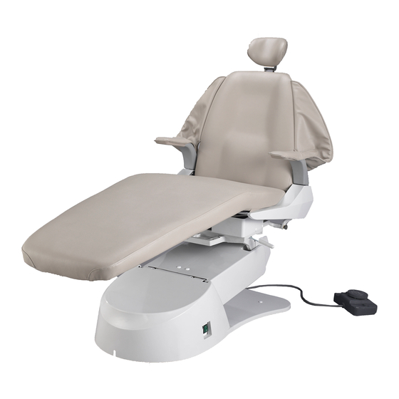
BEL-20+ CHAIR
This manual provides installation instructions for the BEL-20+ Chair.
The instructions contained in this booklet should be thoroughly read and understood
before installation of the chair.
After the installation has been completed, keep this manual in a safe place.
Series
(Plus)
Installation
Instructions
IMPORTANT
R
1E0079A0
Advertisement

Related Manuals for Belmont X-Calibur Series


Summary of Contents for Belmont X-Calibur Series
- Page 1 Series BEL-20+ CHAIR (Plus) Installation Instructions IMPORTANT This manual provides installation instructions for the BEL-20+ Chair. The instructions contained in this booklet should be thoroughly read and understood before installation of the chair. After the installation has been completed, keep this manual in a safe place. 1E0079A0...
-
Page 2: Table Of Contents
Table of Contents 1. Overview and major components ---------------- 1 2. Dimentions and Specifi cations ------------------- 2 3. Introduction ------------------------------------------ 3 4. Installation ------------------------------------------- 3 5. Diagrams --------------------------------------------- 8 Intended Use of the Product This product is intended for the exclusive use for diagnoses, treatments and relative procedures of dentistry, and must be operated or handled by the qualifi... -
Page 3: Overview And Major Components
1. OVERVIEW, MAJOR COMPONENTS AND SYMBOLS 1-1. Overview and major components 1. Headrest Assembly 8. Safety Plate 15. Seat height control 2. Backrest Cushion 9. Base Cover (Seat Raise/lower) 3. Sling 10. Seat Cushion 16. Backrest control 4. Armrest 11. Pump Cover (Backrest Raise/recline) 5. -
Page 4: Dimentions And Specifi Cations
2. Dimensions and Specifi cations 2-1 Dimensions (Inches) 57-7/8 23-3/8 20° 18-1/2 8° 10-1/4 10° 70° 7-5/8 20° 10° 73-5/8 21-5/8 13-5/8 4-3/4 36-1/4 21/1-4 36-1/4 26-3/8 (max 21-1/4) 73-1/2 73-1/2 Minimum 18” Minimum 22” to any object to wall at lowest at lowest position position... -
Page 5: Introduction
3. Introduction 3-1 Precautions for Installation • Keep the equipment away from water. • Keep in a circumstances safe from infl uance by temparature, humidity, wind, sun light, air containig salts and minerals. • Care about stability such as inclination, vibration and inpact, including handling and transportation. •... - Page 6 3) Lift chair base from pallet into the installation location. Be sure to lift chair under the side frame. (See Fig 4-1-3) Side Frame CAUTION Do not lift chair by toeboard bar Fig 4-1-3 Red Shipping Bolt 4) Place the chair on a horizontal fl oor. Remove the red tagged ship- ping bolt from the seat structure using a 13mm socket (See Fig 4-1-4) CAUTION...
- Page 7 4-2 Installation 1) Remove the following items from chair packaging • Backrest Frame Assembly • Metal Seat • Plastic Base Cover • Small carton box containing Armrests, headrest mechanism and bag of hardware. 2) Plug chair into 120VAC outlet. CAUTION To avoid the risk of electrick shock, this equipment must only be connected to a supply mains with protective earth.
- Page 8 7) Remove 4 screws securing back- Socket Screw M10 x 30mm Backrest rest cover to backrest frame. Attach and spring washer M10 quick connect backrest frame using 4 large screws. Connect backrest quick connect plug to chair. Tie up any excess wire. See Fig 4-2-3 Fig 4-2-3 Backrest Cushion...
- Page 9 11) Attach plastic base cover and pump covers to the base plate. Also, securely hold the chair to the fl oor with anchor bolts or large wood screws. Flat head screw M5 x 10, plastic washer and cap 12) After the installation has been completed, check all the Fig 4-2-7 chair functions as per operation manual.
-
Page 10: Diagrams
Using the foot control, backrest controls or optional touchpad, move the seat to the desired position (seat low, seat high, backrest recline and backrest up). Press and release orange button located on the PCB marked “Store”, then using the foot control, backrest controls or optional touchpad press and release the desired limit you wish to set. - Page 11 5-2 Electric diagram...
- Page 12 NOTE BELMONT EQUIPMENT, Division of Takara Belmont USA, Inc. 101 Belmont Drive Somerset, New Jersey 08873 U.S.A. TEL.:(732) 469-5000 / (800) 223-1192 Fax.:(732)526-6322 / (800) 280-7504 TAKARA CO, CANADA LTD. 2076 S. Sheridan Way, Mississauga, Ont., L5J2M4, Can. TEL.:(905) 822-2755 Fax.:(905)822-6203...
Need help?
Do you have a question about the X-Calibur Series and is the answer not in the manual?
Questions and answers