Table of Contents
Advertisement
OPERATING INSTRUCTIONS
Thank you for purchasing TAKARA BELMONT product.
Please read through this instruction manual carefully before using the product to ensure proper
use. Failure to read the instruction manual before use may lead to an accident.
After the installation has been completed, keep this instruction manual near the product for
future maintenance. Refer this manual as needed.
If you have any questions about this Manual or this product, please contact us.
If manual becomes unreadable or is lost, please request a new manual by contacting your dealer.
Installation should be conducted by authorized personnel only.
Follow instructions on installation manual.
DENTAL UNIT AND CHAIR
0197
2015-08 (FE)
BOOK NO. 1E04SDAE
Advertisement
Table of Contents

Related Manuals for Belmont Voyager III


Summary of Contents for Belmont Voyager III
- Page 1 DENTAL UNIT AND CHAIR OPERATING INSTRUCTIONS Thank you for purchasing TAKARA BELMONT product. Please read through this instruction manual carefully before using the product to ensure proper use. Failure to read the instruction manual before use may lead to an accident.
-
Page 3: Table Of Contents
TABLE OF CONTENTS INTENDED USE OF THE PRODUCT SYMBOLS SAFETY PRECAUTION (Please observe safety precautions fully) 1 ~ 9 OVERVIEW AND MAJOR COMPONENTS LOCATION OF THE LABELS OPERATIONS / FUNCTIONS 12 ~ 25 CARE AND MAINTENANCE 26 〜 31 STORAGE/LIFETIME/CONSUMABLE PARTS/STOCK PERIOD OF PARTS BEFORE ASKING FOR REPAIRS DIMENSIONS AND SPECIFICATIONS 35 〜... -
Page 4: Intended Use Of The Product
This unit should be combined with the dental light described in the list of compatible dental light. Important Notes In case of the trouble, please contact a Takara Belmont office or your dealer. Do not disassemble or attempt to repair. -
Page 5: Symbols
SYMBOLS In this manual, on the labels, on the control panel of Voyager III, following symbols are used. Confirm the meaning of each symbol. Symbol Description Symbol Description Symbol Description Symbol Description Protective earth Chair manual OFF (power) ON (power) - Page 6 SAFETY PRECAUTIONS (Please observe safety precautions fully) Before use, read the “Safety precautions” carefully to ensure proper use. The following information is designed to ensure safe use of this product and to prevent injury and damage to you and others. The precautions contained here are classified depending on the severity and degree of imminence of possible injury or damage resulting from improper use.
- Page 7 SAFETY PRECAUTIONS (Please observe safety precautions fully) WARNING 9. Immediately wipe off any water spills or leakage on the floor Immediately wipe off any water spills or leakage on the floor. This could cause damage to the product, decreased strength of the floor may lead to physical injury including fall, or property damage.
-
Page 8: Safety Precaution (Please Observe Safety Precautions Fully) 1
SAFETY PRECAUTIONS (Please observe safety precautions fully) CAUTION 1. Only experienced personnel should use this product Only dentists or other dental professionals should use this product. 2. Confirm safety before use Before use, confirm that the parts are correctly and safely operating and that there are no obstacles around this product. 3. - Page 9 SAFETY PRECAUTIONS (Please observe safety precautions fully) CAUTION 12. Be sure to operate switches with your hands Be sure to operate switches with your hands, except the foot controller, which is operated with your foot. Operation with body parts other than hands may cause damage or incorrect operation. 13.
- Page 10 SAFETY PRECAUTIONS (Please observe safety precautions fully) CAUTION 23. Precautions for after using of the syringe ・ After use, wipe off syringe nozzle, body contaminated with blood or saliva and clean it with cleaning agent as necessary. ・ Sterilization with autoclave, be sure to use sterilization pouch. ・...
- Page 11 SAFETY PRECAUTIONS (Please observe safety precautions fully) CAUTION 32. Precautions for cleaning the vacuum and saliva ejector line Do not use strongly acidic cleaning agents or alkaline pipe cleaning agents, which may cause corrosion of metals, etc. 33. Precautions for cleaning of the spittoon bowl •...
- Page 12 SAFETY PRECAUTIONS (Please observe safety precautions fully) NOTICE Troubleshooting and contact information In the case of any problems, discontinue use, turn off the main switch and contact the dealer or our company. Check operation of the compressor With no air supplied, this product does not operate even after turning on the main switch. Turn on the power of the compressor before operating this product.
- Page 13 SAFETY PRECAUTIONS (Please observe safety precautions fully) PRACTICE OF FLUSH OUT PRECAUTIONS FOR WATER QUALITY CAUTION Practice the flush out of water retained in the unit at the beginning of each workday to maintain the quality of dental treatment water and ensure a steady supply of water to handpieces. After this unit has not been used for a long period of time (at the beginning of the week, in the morning, etc.), water retained in the hose inside the unit or water heater will create an environment where unwanted bacteria are likely to grow.
- Page 14 SAFETY PRECAUTIONS (Please observe safety precautions fully) Caution Points During Operation of the Product Description of Symbol Marks Caution areas such as moving parts, rotating parts and detachable parts to which caution should be paid. Caution areas that are provided with an emergency stop mechanism. Be aware of contact with the assistant’s Take care not to be trapped by the lower part of the instrument holder.
-
Page 15: Overview And Major Components
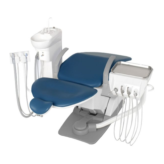
OVERVIEW AND MAJOR COMPONENTS 1. Overview and Major Components 1-1. Overview Cuspidor Unit Cuspidor Bowl Solids Collector Armrest Assistant Holder Doctor Unit Headrest Doctor Table Backrest Handle Doctor Arm Foot Switch Instrument Holder Foot Controller 1-2. Junction Box Section Water main valve Water Main Valve Fuse Holder Turn clockwise to open and counterclockwise... -
Page 16: Location Of The Labels
LOCATION OF THE LABELS 2. Location of the Labels Labels are located on the product as below. Type B Applied Parts Seal Type B Applied Parts Seal Label for Cuspidor needle 2015 Manual reference label Type B Applied Parts Seal Caution label CAUTION - Electric shock hazard, do not remove cover. -
Page 17: Operations / Functions 12
OPERATIONS AND FUNCTIONS 3. Operation MASTER Switch NOTE With no air supplied, this product does not operate even after turning on the main switch. Turn on the power of the compressor before operating this product. 3-1. Master Switch Turn on the master switch located under the doctor table, the master switch indicator located on the front Master Switch side of the cuspidor unit turns to green. - Page 18 OPERATIONS AND FUNCTIONS 3-3. Cuspidor Unit Section Cupfiller Button (1) Cupfiller Keep pressing the cupfiller button until a cup is Bowl Flush filled with water. Control Knob (2) Bowl Flush Turn the bowl flush control knob counterclockwise, Decrease water flushes into the cuspidor bowl. Increase Further turning counterclockwise, increases the amount of flush water.
- Page 19 OPERATIONS AND FUNCTIONS 3-6. Doctor Arm Front Arm Table Height Adjustment • Doctor table height can be adjusted 3 positions. Collar • Hold and slightly lift up the doctor table, stopper ring will come up on upper swing arm post. Slide up or down the stopper ring to appropriate groove on upper swing arm post.
- Page 20 OPERATIONS AND FUNCTIONS 3-10. Waste Receptacle (Optional) * Be careful it has a sharp edge • Replace the paper cup removing from the holder when waste accumulates. • The stainless waste receptacle may be detached when it is turned in direction A. It is fastened when turned in direction B.
- Page 21 OPERATIONS AND FUNCTIONS 3-15. Micromotor rotation control (optional) (1) Micromotor limit rotation speed control knob (1) Micromotor limit Rotation The knob controls the upper limit speeds in micromotor speed control knob rotation. If the knob is turned right, the upper limit speed increases, and if left, the speed decreases.
- Page 22 OPERATIONS AND FUNCTIONS 3-16. Electric Scaler output power control (optional) (1) Scaler output power (1) Scaler output adjustment knob adjustment knob The knob adjusts the output power of the electric scaler. If the knob is turned right, the output power increase, and if left, the power decreases. (2) Scaler Endo/ Scaling/ Perio selector switch Varios 170 scaler have 3 modes such as E (ENDO), S (SCALING) and P (PERIO) and can be chose a mode...
- Page 23 OPERATIONS AND FUNCTIONS 4. CHAIR OPERATING INSTRUCTIONS 4-1. MAIN SWITCH Turn on the main switch located on the left side of the pump cover. A green lamp in the main switch will illuminate. WARNING Be sure to turn off the main switch upon completion of work or during work breaks. This prevents incorrect operation due to accidental contact and associated hazards.
- Page 24 OPERATIONS AND FUNCTIONS (2) Chair Auto Switch Chair Preset Switch • Momentarily press the switch, the chair will move to desired preset 1 position automatically. • Momentarily press the switch, the chair will move to desired preset 2 position automatically. Auto Return Switch Momentarily press the switch will lower the chair to...
- Page 25 OPERATIONS AND FUNCTIONS 4-3. Touch Pad (Optional) Chair Manual Switch Touch Pad Chair Last Position Switch Chair Auto Return Switch 0 Chair Preset Switch 2 1 Chair Preset Switch (1) Chair Manual Switch Switches for manual up/down/backrest reclining of the chair.
- Page 26 OPERATIONS AND FUNCTIONS 4-4. Chair motion stop function (safety function) Sub Link Cover Chair Lock Switch When pressure is detected between the base and the When the doctor table is turned to the back side sub link cover. The chair will moving up for a of the backrest and chair auto motion of the chair is certain period of time and stopped automatically.
- Page 27 OPERATIONS AND FUNCTIONS 4-6. Chair Auto Operation Setting Chair Preset Switch ( 1 ) Preset position setup procedures Chair Manual Switch 1. Move the chair to the treatment position using manual Chair Preset Switch switches. 2. Upon deciding of the desired treatment position, keep pressing preset switch to be set for about 5 seconds.
- Page 28 OPERATIONS AND FUNCTIONS 4-8. IO5000 Dental Light (Type 520-VG) (1) Touchless Switch The dental light turned on when you approach your hand within approximately 60 mm from the touchless switch surface. It goes out when you approach your hand again. * If the surface of a touchless switch becomes unclean, Reaction distance Approx.
- Page 29 OPERATIONS AND FUNCTIONS 4-10. 300LED Dental Light (Type 320S) (1) Touchless Switch The dental light turned on when you approach your hand within approximately 65 mm from the touchless switch surface. It goes out when you approach your hand again. Volume * If the surface of a touchless switch becomes unclean, this may affect the sensitivity of the sensor.
- Page 30 OPERATIONS AND FUNCTIONS 5. Right/Left handed dentistry conversion Please confirm before convert to right or left handed position 1 Bring the chair to the lowest position and backrest upright position. • Turn off the main switch for safety. • Confirm that there are no obstacles around this product. Example : Change Right handed position to left handed Lock lever A position.
-
Page 31: Care And Maintenance 26
CARE AND MAINTENANCE 6. Care and Maintenance Dr table section 6-1. Unit Section ( 1 ) Cleaning and disinfection of product exterior Do NOT spray directly • Use FD366 made by Durr or ethanol as sprayed to a soft cloth for cleaning and disinfection of the product exterior. - Page 32 CARE AND MAINTENANCE ( 4 ) Handpiece 1. Vacuum Handpiece / Saliva Ejector Handpiece Cleaning must be done every after use to patients. For effective sterilization, washing for removing Vacuum Tip contamination and immersion by a cleaning agent are Upper required.
- Page 33 CARE AND MAINTENANCE [ Sterilization ] Sterilization must be done every after use to patients. Vacuum Tip/Vacuum Cap/ Vacuum Handpiece Body/ Saliva Ejector Handpiece Body can be autoclave. Vacuum handpiece body and saliva ejector body have to assemble before autoclave. A.
- Page 34 CARE AND MAINTENANCE 4. Cleaning of Belmont 77 syringe Syringe body [ Disassembly ] Remove the nozzle from syringe by turning it in direction A. [ Cleaning by hand ] 1. Wipe off the surface contamination by a cloth while rinsing the surface by running clean warm water at 40±...
- Page 35 CARE AND MAINTENANCE 5. Handpiece hose Carefully wipe away the filth from the handpiece hose using soft cloth moistened with alcohol or the like. 6. Oil mist separator Oil Mist Filter Handpiece oil mist separator is located rear side of the Packing doctor table.
- Page 36 CARE AND MAINTENANCE 6-2. Chair Section • The surface of the chair’s seating area is made of synthetic leather. Apply dry wiping, wipe the surface with wet cloth or moistened with a 10% detergent solution diluted using water. In case the synthetic leather is wiped with a wet cloth, fully wipe off the moisture with dry cloth.
- Page 37 CARE STORAGE / LIFETIME / CONSUMABLE PARTS / STOCK RERIOD OF PARTS 7. Care Storage, Lifetime, Disposal and Restrictions of Use 7-1. Storage method Strictly observe the following points when the product will not be used for a long period of time. 1.
-
Page 38: Before Asking For Repairs
CARE AND MAINTENANCE BEFORE ASKING FOR REPAIRS If any of phenomena described below has occurred, make the following checks before asking for repairs. Phenomenon Check point and result Action to be taken MASTER Switch/Main Switch is not on. Turn on MASTER Switch/Main Switch. -
Page 39: Dimensions And Specifications
DIMENSIONS AND SPECIFICATIONS 9. Specifications Product Code --------------------------------- AC-V3L-C230VL Power Consumption ------------------------- AC230V 4.0A/4.0A Frequency ------------------------------------- 50/60Hz Fuse -------------------------------------------- Primary Junction Section : 8.0A/250V (Breaking capacity : 80A/250VAC) Operating speed : Time lag Size : 5.0 x 20mm Chair : 5A/250V (Breaking capacity : 50A/250VAC) Operating speed : Fast blow Size : 5.0 x 20mm Power Plug... - Page 40 MAINTENANCE AND INSPECTION 10. Maintenance and Inspection 10-1. Guide for daily maintenance and inspection (Maintenance and inspection by user) Management of maintenance and inspection of medical equipment should be implemented by the user (medical institution). In case the user does not implement such management, it is permitted that such management is outsourced to a qualified entity such as a medical equipment repair company.
- Page 41 MAINTENANCE AND INSPECTION Influence if inspection Maintenance required in case Inspection method Item Frequency and diagnosis not conducted of nonconformity Care Chemical, filthy water and so forth Discoloration and After Execute wiping in accordance Exterior shall not be found (attached or deterioration to the closing with "Method for care"...
- Page 42 MAINTENANCE AND INSPECTION 10-2. Guide for Periodical Check-up Some parts and components of the products are degraded or deteriorated depending on the frequency of use. Annual check-up and maintenance, as well as replacement of consumable parts, are required. The required parts (including consumable parts) are listed below. It may be different from the following list depending on the option of the unit.
- Page 43 Guidance and manufacture’s declaration – electromagnetic emissions The VOYAGER III Unit is intended for use in the electromagnetic environment specified below. The customer or the user of the VOYAGER III Unit should assure that it is used in such an environment.
- Page 44 Guidance and manufacture’s declaration – electromagnetic immunity The VOYAGER III Unit is intended for use in the electromagnetic environment specified below. The customer or the user of the VOYAGER III Unit should assure that it is used in such an environment.
- Page 45 LIST OF CPMPATIBLE HANDPIECES 12. List of Compatible Handpiece LUZZANI 3WAY Minilight w / Light SYRINGE DCI 3WAY TURBINE NSK Ti-Max X AIR MOTOR NSK EX-203 / EX-6 BIEN AIR MX2 / OPTIMA MX2 INT NSK NLX plus MICROMOTOR NSK NLX nano BIEN AIR MCX NSK VARIOS VS170 SCALER NSK VARIOS VS170 LUX SCALER...
-
Page 46: 13. List Of Compatible Dental Light
LIST OF CPMPATIBLE DENTAL LIGHT 13. List of Compatible Dental Light IO5000 DENTAL LIGHT 520-VG DENTAL LIGHT 701 DENTAL LIGTH 720VGM 300LED DENTAL LIGHT TYPE 320S... -
Page 47: Declaration Of Conformity
Directive: 93/42/EEC and RoHS Directive: 2011/65/EU based on category 8 of Annex I. Product : DENTAL UNIT AND CHAIR (CLASS IIa) Model : VOYAGER III " CLASS IIa " has been defined by the rule 9 of MDD Annex IX. - Page 48 Takara Belmont (UK) Ltd. TAKARA BELMONT CORPORATION Belmont House 2-1-1, Higashishinsaibashi,Chuo-ku,Osaka, 542-0083,Japan One St.Andrews Way,Bow, TEL : +81 6 6213 5945 FAX : +81 6 6212 3680 London E3 3PA U.K. Tel: (44)20 7515 0333 Fax:(44)20 7987 3596...
Need help?
Do you have a question about the Voyager III and is the answer not in the manual?
Questions and answers