Belmont Clesta II Installation Instructions Manual
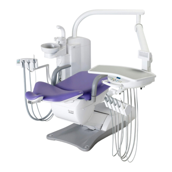
Dental chair
Hide thumbs
Also See for Clesta II:
- Operating instructions manual (40 pages) ,
- Installation instructions manual (24 pages) ,
- Operating instructions manual (40 pages)
Advertisement
Quick Links
This manual provides installation instructions for the BELMONT CLESTA-II.
The instructions contained in this booklet should be thoroughly read and
understood before attempting installation of chair.
After the installation has been completed, keep this manual in a safe place and
refer to it for future maintenance.
DENTAL CHAIR
IMPORTANT
INSTALLATION
INSTRUCTIONS
Advertisement

Related Manuals for Belmont Clesta II


Summary of Contents for Belmont Clesta II
- Page 1 INSTALLATION INSTRUCTIONS IMPORTANT This manual provides installation instructions for the BELMONT CLESTA-II. The instructions contained in this booklet should be thoroughly read and understood before attempting installation of chair. After the installation has been completed, keep this manual in a safe place and...
-
Page 3: Table Of Contents
TABLE OF CONTENTS Page 1. OVERALL VIEW AND MAJOR COMPONENTS - ------------------------- 1 2. DIMENSIONS AND SPECIFICATIONS ------------------------------------- 2 3. INSTALLATION INSTRUCTIONS 3-1. UNPACKING ---------------------------------------------------------------- 3 3-2. INSTALLATIONS ----------------------------------------------------------- 3 4. SPEED ADJUSTMENT ---------------------------------------------------------- 9 5. HYDRAULIC DIAGRAM------------------------------------------------------ 10 6. ELECTRICAL DIAGRAM ----------------------------------------------------- 11... -
Page 4: Overall View And Major Components
1. OVERALL VIEW AND MAJOR COMPONENTS [Standard Base] [Compact Base] Fig.1-1 Overall View Major Components (1) Headrest (12) Backrest Rear Cover (2) Backrest (13) Back Support Cover (3) Back Support (14) Upper Flange Cover (4) Armrest (Left) (15) Main Switch Panel (5) Seat (16) Foot Control (6) Flange (17) Base Cover (7) Lower Flange Cover (18) Base Side Cover R (8) Flange Hose Cover (19) Base Side Cover L (9) Base (10) Pump Cover (11) Headrest Rear Cover... -
Page 5: Dimensions And Specifications
2. DIMENSIONS AND SPECIFICATIONS 2-1. DIMENSIONS (-mm-) [Standard Base] 1188 1813 [Compact Base] 1175 1813 2-1. SPECIFICATIONS Seat Initial Height------------------------------- 410mm Seat Lifting Stroke ------------------------------ 380mm Backrest Movement ---------------------------- 0˚ ~ 80˚ above Horizontal Tilting Mechanism ------------------------------ Backrest Synchronized Tilting (5˚... -
Page 6: Installation Instructions 3-1. Unpacking
3. CHAIR SECTION PREPARATION FOR INSTALLATIONS 3-1. CHAIR SECTION UNPACKING The chair is delivered 2 cartons (base section and top section cartons). Open the upper section carton and check the contents with following check list. CAUTION Do not use sharp instrument, it may damage upholstery. Do not install on wet floor. Check List for Upper Section Carton 1. - Page 7 (3) Remove the pump cover. Remove wood screws from the base. Remove the base section from the pallet by holding the carriage bars (Front side and Rear side) and place it at the planned location. (Fig.3-2) [Standard Base] [Compact Base] Pump Cover Wood Screw Pump Cover Rear Side Wood Carriage Bar Screw Wood Screw Mats Wood Screw Mats Pallet...
- Page 8 (8) Remove the support plate and fix the lower flange cover under the flange. (Fig.3-4) Note : Mount the Clesta-II unit on the chair before removing the support plate. Refer to the Unit installation manual. Support Plate Mats Lower Flange Cover Mats Mats...
- Page 9 (10) Open the top section carton. Backrest cushion, backrest cover, headrest, armrest, seat and screw kit are packed in top section carton. (11) Fix the back support plate to the back support by 4 x M8 cap bolts and spring washers. (Fig.3-6) Back Support Plate M8x25 Cap Bolt Back Support...
- Page 10 (15) Fix the seat to the chair base. Hook the seat hooks under the seat fixing plates on the chair base and secure the seat to the seat frame with 2 x M6 screws and flat washers. (Fig.3-9) Seat Seat Fixing Plate M6 Screw Mats...
- Page 11 (19) Fix the pump cover to the base with 3 x M5 (19) Attach the pump cover to the base. Fix the pump screws. (Fig.3-13a) cover and base cover to the base with two x M5 x 12 white truss screws. (Fig.3-13b) [Standard Base] [Compact Base] Pump Cover M5 Screw...
-
Page 12: Speed Adjustment
4. SPEED ADJUSTMENT (Fig.4-1 and Fig.4-2) Seat lowering speed and backrest reclining speed can be adjusted by the speed control knob on the solenoid valve block.. The solenoid valve numbers and functions are shown in Fig.4-1. A. Remove the pump cover. The solenoid valve block is located on the left side at the front of the chair base. Each speed control knob is located on the rear side solenoid valve block. -
Page 13: Hydraulic Diagram
5. HYDRAULIC DIAGRAM Seat Elevation Backrest Cylinder Cylinder Accumulater Reservoir Solenoid Valve Block Motor Pump : Filter : Check Valve : Flow Adjustable Solenoid Valve : Solenoid Valve Fig.5-1 Hydraulic Diagram -10-... -
Page 14: Electrical Diagram
6. ELECTRICAL DIAGRAM -11-... - Page 16 TAKARA BELMONT CORPORATION 1-1, 2-Chome, Higashi-shinsaibashi,Chuo-ku,Osaka,Japan TEL : (06) 6213-5945 FAX : (06) 6212-3680 BOOK NO. AEFT01EE Printed in Japan 2017-12...
Need help?
Do you have a question about the Clesta II and is the answer not in the manual?
Questions and answers