Belmont CREDIA G1 Operating Instructions Manual
Hide thumbs
Also See for CREDIA G1:
- Installation instructions manual (28 pages) ,
- Instructions for use manual (20 pages)
Table of Contents
Advertisement
DENTAL UNIT
OPERATING INSTRUCTIONS
Thank you for purchasing TAKARA BELMONT product.
Please read through this instruction manual carefully before using the product
to ensure proper use. Failure to read the instruction manual before use may lead
to an accident.
After the installation has been completed, keep this instruction manual near the
product for future maintenance. Refer this manual as needed.
If you have any questions about this Manual or this product, please contact us.
If manual becomes unreadable or is lost, please request a new manual by
contacting your dealer.
Installation should be conducted by authorized personnel only.
Follow instructions on installation manual.
BOOK NO. 1E03V3S0 (17E)
Printed in Vietnam 2021-05
1639
Advertisement
Table of Contents

Subscribe to Our Youtube Channel
Related Manuals for Belmont CREDIA G1


Summary of Contents for Belmont CREDIA G1
- Page 1 Printed in Vietnam 2021-05 DENTAL UNIT OPERATING INSTRUCTIONS Thank you for purchasing TAKARA BELMONT product. Please read through this instruction manual carefully before using the product to ensure proper use. Failure to read the instruction manual before use may lead to an accident.
-
Page 3: Table Of Contents
TABLE OF CONTENTS Page SAFETY PRECAUTIONS --------------------------------------------------- 1 ~ 5 OPERATING PRECATIONS ----------------------------------------------- 6 PRACTICE OF FLUSH OUT ----------------------------------------------- 7 OVERVIEW AND MAJOR COMPONENTS ---------------------------- 8 ~ 9 LOCATION OF THE LABELS --------------------------------------------- 10 DESCRIPTION OF OPERATION AND FUNCTIONS OF COMPONENTS ---------------------------------- 11 ~ 18 1. - Page 4 Use the dental light described on page 36. Important Notes In case of the troubles, please contact Takara Belmont offices or your dealers. Do not disassemble or attempt to repair. Disassembly, repair or modifications should only be done by a qualified repair technician.
- Page 5 SYMBOLS In this manual, on the labels, on the control panel of CREDIA G1, following symbols are used. Confirm the meaning of each symbol. Protective earth Functional earth ON (power) OFF (power) (ground) (ground) Alternating current Chair last position Chair auto return...
-
Page 6: Safety Precautions
SAFETY PRECAUTIONS Before use, read the “Safety precautions” carefully to ensure proper use. The following information is designed to ensure safe use of this product and to prevent injury and damage to you and others. The precautions contained here are classified depending on the severity and degree of imminence of possible injury or damage resulting from improper use. - Page 7 Portable RF communications equipment (including peripherals such as antenna cablesand external antennas) should be used no closer than 30 cm (12 inches) to any part of the CREDIA G1, including cables specified by the manufacturer. Otherwise, degradation of the performance of this euipment could result.
- Page 8 SAFETY PRECAUTIONS CAUTION 5. Keep your eyes on the patient during operation. • Confirm that the patient is seated in the proper position. Keep your eyes on the patient during the operation. • Pay special attention to surroundings at automatic operation of the dental treatment table. Damage to the backrest, stool or Doctor's table may occur.
- Page 9 SAFETY PRECAUTIONS NOTICE 1. Troubleshooting and contact information In the case of any problems, discontinue use, turn off the main switch and contact the dealer or our company. 2. Check operation of the compressor With no air supplied, this product does not operate even after turning on the main switch. Turn on the power of the compressor before operating this product.
- Page 10 SAFETY PRECAUTIONS Caution Points During Operation of the Product Description of Symbol Marks : Caution areas such as moving parts, rotating parts and detachable parts to which caution should be paid. : Caution areas that are provided with an emergency stop mechanism. Over the Patient, Holder Type Over the Patient, Rod Type (Continental Type) Long Armrest (Optional)
-
Page 11: Operating Precations
OPERATING PRECAUTIONS Please observe following cautions to avoid the damage. CAUTION 1. Do not place anything hot on the unit Do not place anything hot on the unit. This could cause deformation or discoloration. 2. Precautions for cleaning of the cuspidor bowl The cuspidor bowl is made of ceramic. -
Page 12: Practice Of Flush Out
PRACTICE OF FLUSH OUT PRECAUTIONS FOR WATER QUALITY CAUTION Practice the flush out of water retained in the unit at the beginning of each work day to maintain the quality of dental treatment water and ensure a steady supply of water to handpieces. After this unit has not been used for a long period of time (at the beginning of the week, in the morning, etc.), water retained in the hose inside the unit or water heater will create an environment where unwanted bacteria are likely to grow. -
Page 13: Overview And Major Components
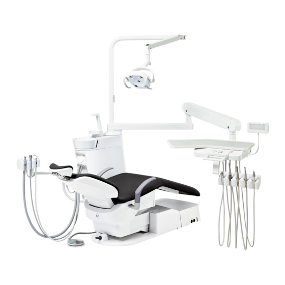
OVERVIEW AND MAJOR COMPONENTS Over the Patient, Holder Type Light Pole Dental Light First Arm (Horizontal Arm) Cuspidor Unit Section Balance Arm Doctor Unit Section Doctor Table Junction Box Foot Controller Over the Patient, Rod Type (Continental Type) Light Pole Dental Light First Arm (Horizontal Arm) Balance Arm... - Page 14 OVERVIEW AND MAJOR COMPONENTS Doctor Unit Section Handpiece Pressure Gauge -Holder Type - Film Viewer Tray Mat Waste Main Switch Receptacle Handle Doctor Unit -Rod Type - Control Panel (Continental Type) Instrument Holder Doctor Unit Control Panel Handle Rest Holder Sub Tray Cuspidor Unit Section Cupfiller Nozzle...
-
Page 15: Location Of The Labels
Product of Vietnam BELMONT MANUFACTURING CO.,LTD Lot I-2, Long Duc Industrial Park, Long Duc Ward, Long Thanh District, Dong Nai Province, Vietnam TAKARA COMPANY EUROPE GmbH Berner Strasse 18, 60437 Frankfurt am Main, Germany Designed by TAKARA BELMONT,JAPAN Product Label... -
Page 16: Description Of Operation
DESCRIPTION OF OPERATION AND FUNCTIONS OF COMPONENTS Doctor Unit Section Main Switch (Back side) Flushout Switch Handpiece Light ON-OFF Switch (Front side) (Holder Type) * Underside of the doctor table Handpiece Pressure Gauge Handpiece Light ON-OFF Switch (Rod Type/Continental Type) Main Switch - Rod Type - (Continental Type) - Page 17 DESCRIPTION OF OPERATION AND FUNCTIONS OF COMPONENTS Doctor Unit Section Doctor Unit Control Panel - Holder Type - - Rod Type - (Continental Type) Cupfiller Switch Cupfiller Switch Chair Control Switch Chair Control Switch Chair Manual Switch • Switches provide manual operation for up/down and backrest reclining/raising of the chair.
- Page 18 DESCRIPTION OF OPERATION AND FUNCTIONS OF COMPONENTS Doctor Unit Section Doctor Unit Control Panel Chair Last Position Switch • When this switch is pressed in the fine-adjusted treatment position, the chair moves to the rinsing position. When the switch is pressed again, the chair returns to the former treatment position.
- Page 19 DESCRIPTION OF OPERATION AND FUNCTIONS OF COMPONENTS Doctor Unit Section Balance Arm Air Brake Button • When the master switch is ON, the balance arm is locked. Grasp the handle and press the air brake botton to adjust the table height. Release the air brake button at the desired table Down position, the balance arm is locked.
- Page 20 DESCRIPTION OF OPERATION AND FUNCTIONS OF COMPONENTS Doctor Unit Section Electric Scaler (Holder Type) Scaler Power Adjustment Knob Handpiece Light ON-OFF Switch Scaler E / S / P Select Switch Scaler Water Adjustment Knob Scaler Power Adjustment Knob • The knob adjusts the output power of the electric scaler.
- Page 21 DESCRIPTION OF OPERATION AND FUNCTIONS OF COMPONENTS Doctor Unit Section Electric Scaler (Rod Type/Continental Type) Scaler Water Adjustment Knob Scaler Power Adjustment Knob Handpiece Light ON-OFF Switch Scaler E / S / P Select Switch Scaler Power Adjustment Knob •...
-
Page 22: Foot Controller
DESCRIPTION OF OPERATION AND FUNCTIONS OF COMPONENTS Foot Controller DCI Foot Controller Pedal Increase by • The pedal depressing extent can control the turbine the degree of Pedal stepping and air motor rotation speed. Chip Blower Button Coolant Water Switch •... -
Page 23: Cuspidor Unit Section
DESCRIPTION OF OPERATION AND FUNCTIONS OF COMPONENTS Cuspidor Unit Section Cuspidor Unit Control Panel Increase Decrease Water heater switch Switch for turning on/off the cupfiller water heater. (The water temperature is set in around 36 degrees and water drips from the cupfiller nozzle when the water in the water heater is heated. - Page 24 DESCRIPTION OF OPERATION AND FUNCTIONS OF COMPONENTS 1 Cuspidor Unit Section Cupfiller Switch • Water is supplied through from the cupfiller nozzle when this switch is pressed. * Do not press the switch while the cup is not in place. Cupfiller Nozzle [Assistant Side] Once the cupfiller switch is pressed, water will come...
- Page 25 DESCRIPTION OF OPERATION AND FUNCTIONS OF COMPONENTS Cuspidor Unit Section Clean Water System • The water bottle CITY/BOTTLE select switch can be changed between municipal water and water Pressurization bottle. ON-OFF Switch CITY ..Tap water CITY/BOTTLE BOTTLE .
-
Page 26: Junction Box Section
DESCRIPTION OF OPERATION AND FUNCTIONS OF COMPONENTS Junction Box Section Drain Valve Power Supply Switch How to open the junction box cover Junction box cover Air Shut OFF Valve Cover fixing screw Water Shut OFF Valve Phillips screwdriver Pressure Gauge Power supply switch •... -
Page 27: Adjustment Of Parts
ADJUSTMENT OF PARTS Doctor Unit Section Flow Adjustment Water adjustment of the handpiece spray • The water flow rates of the handpiece of the Handpiece spray Doctor’s unit may be adjusted with the knob water control knob (blue knob). •... -
Page 28: Junction Box Section
ADJUSTMENT OF PARTS Cuspidor Unit Section Flow Adjustment * Flow control knobs are located on the inside of the How to open the side cover cuspidor unit. Loosen the side cover fixing screw by Side cover flat head screwdriver on the rear side of the cuspidor unit. -
Page 29: Care And Maintenance
CARE AND MAINTENANCE Doctor Unit Section - Rod Type - - Holder Type - (Continental Type) Oil Mist Separator Oil Mist Separator Tray Mat Waste Waste Receptacle Receptacle Handle Doctor Table Doctor Table Control Panel Control Panel Handle Doctor Side Rest Holder Instrument Holder... - Page 30 CARE AND MAINTENANCE Doctor Unit Section Sub Tray (Rod Type/Continental Type) • Use FD333 or FD366 made by Durr or ethanol as sprayed to a soft cloth for cleaning and disinfection of the sub tray. Doctor Instrument Holder (Holder Type) •...
- Page 31 CARE AND MAINTENANCE Doctor Unit Section Doctor Table Control Panel (Membrane Switch) • Use FD333 or FD366 made by Durr or ethanol as (Rod Type) sprayed to a soft cloth for cleaning and disinfection. Continental Type Wipe off with dry soft cloth to dried up of the doctor (Holder Type) ...
-
Page 32: Cuspidor Unit Section
CARE AND MAINTENANCE Cuspidor Unit Section Cleaning of cuspidor bowl section • Use Orotol Plus made by Durr to cleaning the cuspidor bowl. • The basket strainer in the cuspidor bowl is easily clogged. Clean it at the end of each work day. When the cap is pulled, the basket strainer also come with the cap. - Page 33 CARE AND MAINTENANCE Cuspidor Unit Section Cleaning of vacuum hose / saliva ejector hose • The vacuum hose and saliva ejector hose can be disconnected and cleaned in running water. Be sure to turn off the main switch of the unit Release before cleaning.
- Page 34 CARE AND MAINTENANCE Cuspidor Unit Section CAUTION Cleaning must be done within 1 hour after use. Replace with a new vacuum handpiece and saliva ejector handpiece for following cases. • Any waste material can not be removed by clogged hole. •...
- Page 35 CARE AND MAINTENANCE Cuspidor Unit Section Sterilization DURR Saliva Ejector Handpiece 1. Insert the handpiece in a sterilization pouch and seal it. 2. Autoclave for 5 min. at 134 * Sterilization with autoclave is permitted up to 250 times. CAUTION •...
-
Page 36: Junction Box Section
CARE AND MAINTENANCE Junction Box Section Cleaning air filter drain valve and discharging water from air compressor • Drain valve is used to discharge water from the air filter. • Turn the drain valve counterclockwise to discharge water collected in the air filter once a week at least. •... -
Page 37: Specifications
: 70kg (without dental light) Dental light : 300LED Dental Light Type 320M (Sensor Type) Dental chair : CREDIA G1 Chair Usage environment : Temperature +10ºC ~ +40ºC : Humidity 30% ~ 75% : Air pressure 700 hPa ~ 1060 hPa Transportation / Storage environment : Temperature -20ºC ~ +70ºC... - Page 38 SPECIFICATIONS Dimensions Values are the standard values. (Unit: mm) Dimensional tolerance: ±10% - Holder Type - - Rod Type - (Continental Type)
-
Page 39: Electromagnetic Compatibility (Emc)
Unit should ensure that it is used in such an environment. CREDIA G1 Emissions test Compliance Electromagnetic environment - guidance The CREDIA G1 Unit only uses RF energy for its internal RF emissions function. Therefore, its RF emissions are very low and are not Group 1 CISPR 11 likely to cause any interference with nearby electronic equipment. - Page 40 ISM and in ISM and used no closer than 30 cm(12 inches) to amateur radio bands amateur radio bands any part of the CREDIA G1 , including Radiated RF 3V/m 3V/m cables specified by the manufacturer. IEC 61000-4-3 80MHz〜2.7GHz...
-
Page 41: Handpieces That Can Be Used With This Product
However, there still could be a case that the connectors of turbines or air motors may not fit into some handpieces due to the manufacturing tolerances. Have your local authorized Belmont dealer check the connectability before purchasing the handpiece. Except for our recommended handpieces, we shall not be liable for any problems deriving from bad connectability or their performance. -
Page 42: Before Asking For Repairs
BEFORE ASKING FOR REPAIRS If any of phenomena described below has occurred, make the following checks before asking for repairs. Phenomenon Check point and result Action to be taken Power plug is not connected. Connect the power plug. No power on the unit Turn on the power. -
Page 43: Storage Method
STORAGE METHOD Strictly observe the following points when the product will not be used for a long period of time (following the completion of work, during the suspension of business, etc.). 1.Main switch • Be sure to turn off the main switch at the end of each work day . (To stop supply of air, water, electric power, etc.) •... -
Page 44: Maintenance And Inspection
MAINTENANCE AND INSPECTION Guide for daily maintenance and inspection (Maintenance and inspection by user) Management of maintenance and inspection of medical equipment should be implemented by the user (medical institution). In case the user does not implement such management, it is permitted that such management is outsourced to a qualified entity such as a medical equipment repair company. - Page 45 MAINTENANCE AND INSPECTION Influence if inspection Maintenance required in case Inspection method Item Frequency not conducted of nonconformity and diagnosis Before Scaler vibration, water flow Troubles such as injury Control the water flow in accor- Check in patient's oral cavity dance with "Flow Adjustment"...
- Page 46 MAINTENANCE AND INSPECTION Inspection method Influence if inspection Maintenance required in case Item Frequency and diagnosis not conducted of nonconformity Care After Chemical, filthy water and Discoloration and Execute wiping in accordance Exterior closing deterioration to the so forth shall not be found with "Method for care"...
-
Page 47: Optional Accessories
OPTIONAL ACCESSORIES Optional accessorieds are listed below. It may be different from the following list depending on the specification of the unit. Intended use Optional Accessories The container to take in cotton and Cotton containers swab for dental treatment. Receptacle to do away with used Waste cotton,etc. - Page 48 Directive: 93/42/EEC and RoHS Directive: 2011/65/EU based on category 8 of Annex I. Product : DENTAL UNIT (CLASS IIa) Model : CREDIA G1 " CLASS IIa " has been defined by the rule 9 of MDD Annex IX. The product has been designed and manufactured in accordance with the European standards as the listed in the Declaration of Conformity.
- Page 49 BELMONT MANUFACTURING CO., LTD. (Manufacturer) Lot I-2, Long Duc Industrial Park, Long Duc Ward, Long Thanh District, Dong Nai Province, Vietnam R E P TEL : +84-2513-201-100 / F AX : +84-2513-201-096 TAKARA COMPANY EUROPE GmbH Berner Strasse 18, 60437...
Need help?
Do you have a question about the CREDIA G1 and is the answer not in the manual?
Questions and answers