Belmont Clesta eIII Installation And Operation Instructions Manual
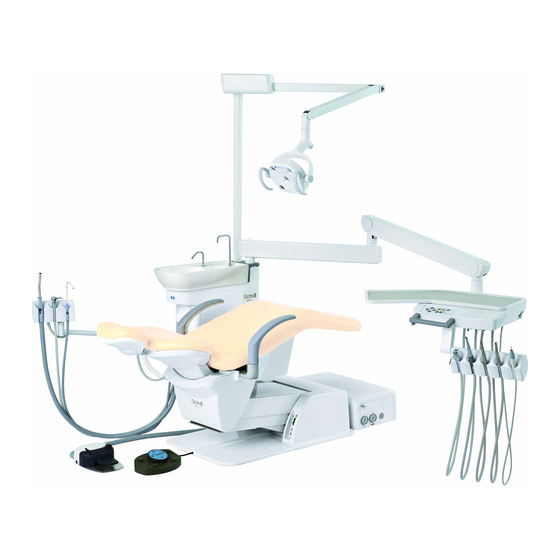
Dental chair
Hide thumbs
Also See for Clesta eIII:
- Installation instructions manual (28 pages) ,
- Instructions for use manual (67 pages)
Table of Contents
Advertisement
OPERATION INSTRUCTIONS
This manual provides installation and operating instructions for the
CLESTA eIII CHAIR.
The instructions contained in this booklet should be thoroughly read and
understood before operating the chair.
After the installation has been completed, keep this manual in a safe place
and refer to it for future maintenance.
If you have any questions about this Manual or this product, please contact us.
If manual becomes unreadable or is lost, please request a new manual
by contacting your dealer.
Installation should be conducted by authorized personnel only.
Follow instructions on installation manual.
DENTAL CHAIR
INSTALLATION
AND
IMPORTANT
Advertisement
Table of Contents

Subscribe to Our Youtube Channel
Related Manuals for Belmont Clesta eIII


Summary of Contents for Belmont Clesta eIII
- Page 1 OPERATION INSTRUCTIONS IMPORTANT This manual provides installation and operating instructions for the CLESTA eIII CHAIR. The instructions contained in this booklet should be thoroughly read and understood before operating the chair. After the installation has been completed, keep this manual in a safe place and refer to it for future maintenance.
-
Page 3: Table Of Contents
Table of Contents INTENDED USE OF THE PRODUCT COMPLIANCE WITH DIRECTIVE CAUTIONS SYMBOLS 1 ~ 4 SAFETY PRECAUTIONS OVERVIEW AND MAJOR COMPONENTS INSTALLATION INSTRUCTIONS Check the Packing ....5 Precautions for Installation . -
Page 4: Intended Use Of The Product
Do not disassemble or attempt to repair. Disassembly repair technician. Attempts at disassembly ad to abnormal operation and accidents. SYMBOLS In this manual, on the labels, on the control switch of CLESTA eIII CHAIR, following symbols are Symbol Description Symbol Description Symbol... - Page 5 SAFETY PRECAUTIONS Before use, read the “Safety precautions” carefully to ensure proper use. The following information is designed to ensure safe use of this product and to prevent injury and damage to you and others. The precautions contained here are class imminence of possible injury or damage resulting from improper use.
- Page 6 16. Prohibition of placing portable RF communications equipment adjacent to this product should be used no closer than 30 cm(12 inches) to any part of the CLESTA eIII CHAIR,including cables specified by the manufacturer.Otherwise,degradation of the performance of this equipment could result.
- Page 7 SAFETY PRECAUTIONS 5. Do not smack or rub this product 6. Keep your eyes on the patient during the chair operation. 7. Precautions for handling synthetic leather 8. Be sure to operate switches with your hands 9. Immediately wipe off drug solution when it comes into contact with this unit 10.
-
Page 8: Safety Precautions 1
SAFETY PRECAUTIONS Caution Points During Operation of the Product Description of Symbol Marks : Caution areas such as moving parts, rotating parts and detachable parts to which caution should be paid. : Caution areas that are provided with an emergency stop mechanism. Take care not to be trapped by moving parts Take care not to be trapped by moving parts of the headrest. -
Page 9: Installation Instructions
INSTALLATION INSTRUCTIONS Check the Packing Check the each quantity of the parts for installation as listed below. 1 set 1. Headrest assembly • • • • • • • • • • • • • • • • • • •... -
Page 10: Preparations For Installation Of The Chair
INSTALLATION INSTRUCTIONS Preparations for Installation of the Chair Coach Bolt Armrest Bracket Carton Box Base Cover Pump Cover Main Link Shaft Pallet Coach Bolt ( 1 ) Remove all the staples fixing the carton box to ( 2 ) Remove the pump cover and the base cover. the pallet and remove the carton. -
Page 11: Installation Of The Armrest And The Seat
INSTALLATION INSTRUCTIONS Installation of the Armrest and the Seat Armrest (L) Armrest (L) Armrest (R) Rubber Washer Collar Flat Washer Spring M6 x 25 Pan Head Screw Flat Washer Rubber Washer ( 2 ) • Fix the right side armrest to the armrest ( 1 ) Left side Armrest (Fixed armrest) Attach the rubber washer to the upper side of the bracket with M6 x 25 screw, flat washer and... -
Page 12: Installation Of The Backrest And The Headrest
INSTALLATION INSTRUCTIONS Installation of the Backrest and the Headrest Spring Washer Backrest Support Plate Backrest Support Plate Backrest Support M8 x 20 Cap Bolt Backrest M5 x 16 Screw ( 1 ) Unscrew the four M5 x 16 screws and ( 2 ) Fix the backrest support plate to the backrest remove the back support plate from the support by four M8 x 20 cap bolts with spring... -
Page 13: Fix The Base On The Floor
INSTALLATION INSTRUCTIONS Fix the Base on the Floor M5 x 10 Button Head Screw Coach Bolt Base Cover Pump Cover M10 x 10 Set Cap Cover Set Screw M5 x 10 Flat Head Screw Set Cap Washer ( 1 ) Adjust the leveling of the base with six M10 x ( 3 ) Attach the pump cover and base cover to the 10 set screws as needed. -
Page 14: Replacement
INSTALLATION INSTRUCTIONS Replacement Replacement must be done by a professional technician(s) of our company or a company authorized by us. Fuse 1. Remove the fuse holder cap by pushing and turning counterclockwise with flat-head screwdriver. 3. Replace the fuse to the specification described in a fuse Fuse holder cap label. -
Page 15: Chair Electrical Diagram
INSTALLATION INSTRUCTIONS Chair Electrical Diagram - 11 -... -
Page 16: Operating Instructions
OPERATING INSTRUCTIONS Main Switch Turn the main switch on (' I ' mark) located on the right side of the pump cover. A green lamp in the main switch will illuminate. Turn the main switch off (' ' mark) will 「... -
Page 17: Twin Articulating Headrest (Optional)
OPERATING INSTRUCTIONS Twin Articulating Headrest (Optional) Height Adjustment Headrest Release Button Hold the headrest section with both hands and adjust headrest height by pulling out or pressing down on the headrest section. & Angle Adjustment Hold the headrest release button to unlock the twin Headrest Section axis mechanism and adjust headrest angle. -
Page 18: Foot Switch
OPERATING INSTRUCTIONS Foot Switch Chair Manual Switch Chair Preset Switch Chair Preset Switch Chair Last Position Switch Chair Auto Return Switch Chair Manual Switch Operating instruction for chair manual operation. Pressing will move the chair up Pressing will move the chair down Pressing will move the backrest reclining Pressing... -
Page 19: Operation Setting
OPERATION SETTING Preset position setup procedures Set the treatment position by chair 1. Move the chair to the treatment position using manual switch chair manual switches. 2. Upon deciding of the desired treatment position, keep pressing chair preset switch or chair auto return switch to be set for about 5 seconds. -
Page 20: Operation Stopping Function
OPERATION STOPPING FUNCTION Chair motion stop function (safety function) The safety mechanism that inhibits chair auto movement (chair preset switch, chair auto return switch, chair last position switch) while any of the following actions are taken. • When pressing the any chair operation switches. •... -
Page 21: Care And Maintenance
CARE AND MAINTENANCE Chair Cleaning and Disinfection • The surface of the chair’s seating area is made of synthetic leather. Apply dry wiping or wipe the surface with cloth moistened with a 10% detergent solution diluted using water. In case the synthetic leather is wiped with a wet cloth, fully wipe off the moisture with dry cloth. -
Page 22: Storage, Lifetime, Stock Period Of Parts And Disposal
STORAGE, LIFETIME, STOCK PERIOD OF PARTS AND DISPOSAL Storage method Strictly observe the following points when the product will not be used for a long period of time. 1. Turn OFF the main switch at the lowest seat position and backrest reclining position after daily operation and for a long term interval. -
Page 23: Specifications
SPECIFICATIONS Seat height : 400 ~ 780 mm (Electro-hydraulic system) Seat lifting stroke : 380 mm Backrest movement : 0° ~ 73° (Electro-hydraulic system) Tilting mechanism : 10° ~ 18° (Backrest Synchronized Tilting) Headrest stroke : 170 mm (Manual operation) Headrest moving angle : 58°... -
Page 24: Maintenance And Inspection
MAINTENANCE AND INSPECTION Guide for daily maintenance and inspection (Maintenance and inspection by user) Management of maintenance and inspection of medical equipment should be implemented by the user (medical institution). In case the user does not implement such management, it is permitted that such management is outsourced to a qualified entity such as a medical equipment repair company. -
Page 25: Electromagnetic Compatibility (Emc) 21
Guidance and manufacturer’s declaration – electromagnetic emissions The CLESTA eIII CHAIR is intended for use in the electromagnetic environment specified below. The customer or user of the CLESTA eIII CHAIR should ensure that it is used in such an environment. - Page 26 WARNING Portable RF communications equipment (including peripherals such as antenna cablesand external antennas) should be used no closer than 30 cm(12 inches) to any part of the CLESTA eIII CHAIR, including cables specified by the manufacturer. Otherwise,degradation of the performance of this equipment could result.
-
Page 27: Declaration Of Conformity
Directive: 93/42/EEC based on ANNEX VII and RoHS Directive: 2011/65/EU based on category 8 of Annex I. Product : DENTAL CHAIR (CLASS I) Model : CLESTA eIII CHAIR " CLASS I " has been defined by the rule 12 of MDD Annex IX. - Page 28 TAKARA COMPANY EUROPE GmbH Berner Strasse 18, 60437 Frankfurt am Main, Germany TAKARA BELMONT CORPORATION Tel:+49 69 506878 0 2-1-1, Higashishinsaibashi,Chuo-ku,Osaka, 542-0083,Japan Fax:+49 69 506878 20 TEL : +81 6 6213 5945 FAX : +81 6 6212 3680 BOOK NO. 1A0BAJLE...
Need help?
Do you have a question about the Clesta eIII and is the answer not in the manual?
Questions and answers