Advertisement
This manual provides installation instructions for the CELEB.
The instructions contained in this booklet should be thoroughly read and
understood before attempting installation of chair.
After the installation has been completed, keep this manual in a safe place and
refer to it for future maintenance.
DENTAL CHAIR
IMPORTANT
INSTALLATION
INSTRUCTIONS
Advertisement

Related Manuals for Belmont Celeb


Summary of Contents for Belmont Celeb
- Page 1 INSTALLATION INSTRUCTIONS IMPORTANT This manual provides installation instructions for the CELEB. The instructions contained in this booklet should be thoroughly read and understood before attempting installation of chair. After the installation has been completed, keep this manual in a safe place and...
-
Page 3: Table Of Contents
TABLE OF CONTENTS Page 1. OVERALL VIEW AND MAJOR COMPONENTS - ------------------------- 1 2. DIMENSIONS AND SPECIFICATIONS ------------------------------------ 2A 3. INSTALLATION INSTRUCTIONS 3-1. UNPACKING ---------------------------------------------------------------- 3 3-2. INSTALLATIONS ----------------------------------------------------------- 3 4. SPEED ADJUSTMENT ---------------------------------------------------------- 6 5. HYDRAULIC DIAGRAM------------------------------------------------------- 7 6. ELECTRICAL DIAGRAM ----------------------------------------------------- 8A... -
Page 4: Overall View And Major Components
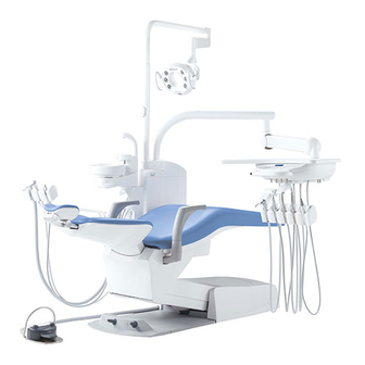
1. OVERALL VIEW AND MAJOR COMPONENTS Fig.1-1 Overall View Major Components (1) Headrest (12) Backrest Rear Cover (2) Backrest (13) Back Support Cover (3) Back Support (14) Upper Flange Cover (4) Armrest (Left) (15) Main Switch Panel (5) Seat (16) Foot Control (6) Flange (7) Lower Flange Cover (8) Flange Hose Cover (9) Base (10) Pump Cover (11) Headrest Rear Cover... -
Page 5: Dimensions And Specifications
2. DIMENSIONS AND SPECIFICATIONS 2-1. DIMENSIONS -mm- 1188 1813 Fig.2-1 Dimensions 2-2. SPECIFICATIONS Seat Initial Height - ------------------------------ 410mm Seat Lifting Stroke ------------------------------ 380mm Backrest Movement ---------------------------- 0˚ ~ 80˚ above Horizontal Tilting Mechanism ------------------------------ Backrest Synchronized Tilting (5˚ ~ 11˚ above Horizontal) Auto Movements - ------------------------------- 2-Preset, 1-Last Position Memory and 1-Auto Return Control Voltage - --------------------------------- DC12V Power Consumption ---------------------------- AC230V, 50/60Hz, 2.0/2.0A Net Weight --------------------------------------- 115 kg -2A-... -
Page 6: Installation Instructions 3-1. Unpacking
3. CHAIR SECTION PREPARATION FOR INSTALLATIONS 3-1. CHAIR SECTION UNPACKING The chair is delivered 2 cartons (base section and top section cartons). Open the upper section carton and check the contents with following check list. CAUTION Do not use sharp instrument, it may damage upholstery. Do not install on wet floor. Check List for Upper Section Carton 1. Headrest Assembly --------------------------------------------------------------------------------------------- 1 set 2. Backrest Assembly - --------------------------------------------------------------------------------------------- 1 set (Backrest Cushion with Backrest Support Plate, Backrest Cover) 3. - Page 7 When fixing chair to the floor, be careful not operation. to damage pipings under the floor. (8) Remove the support plate and fix the lower flange cover under the flange. (Fig.3-4) Note : Mount the CELEB unit on the chair, before removing the support plate. Carriage Bar Hole Plug Refer to the Unit installation manual.
- Page 8 Backrest Cushion M5 x 25 (12) Fix the backrest cushion to the back support Screw plate by 4 x M5 screws. (Fig.3-7) Back Support Plate Fig.3-7 Fixing Backrest Cushion (13) Attach the backrest cover to the backrest cushion. Insert upper two hooks of the backrest cover into the upper fixing holes of backrest.
-
Page 9: Speed Adjustment
(17) Fix the pump cover to the base with 3 x M5 M5 Screw screws. (Fig.3-11) Note : Mount the CELEB unit on the chair, before fixing the pump cover. Refer to the Unit installation manual. Pump Cover After installation is completed, check Mats all movement by following the M5 Screw operating manual. Fig.3-11 Fixing Pump Cover 4. -
Page 10: Hydraulic Diagram
5. HYDRAULIC DIAGRAM Seat Elevation Backrest Cylinder Cylinder Accumulater Reservoir Solenoid Valve Block Motor Pump : Filter : Check Valve : Flow Adjustable Solenoid Valve : Solenoid Valve Fig.5-1 Hydraulic Diagram... -
Page 11: Electrical Diagram
6. ELECTRICAL DIAGRAM -8A-... - Page 12 NOTE TAKARA BELMONT CORPORATION 1-1, 2-Chome, Higashi-shinsaibashi,Chuo-ku,Osaka,Japan TEL : (06) 6213-5945 FAX : (06) 6212-3680 BOOK NO. 1E0321C0 Printed in Japan 2014-05...
Need help?
Do you have a question about the Celeb and is the answer not in the manual?
Questions and answers